Ambient Math: Interfacing the Photoresistor
The Photoresistor (LDR - Light Dependent Resistor) is fundamentally the second most important component in embedded hardware (after the LED). It teaches the core engineering concept of the "Voltage Divider," which is required to measure almost every single analog sensor in existence from thermistors to flex-sensors.
The Problem With Raw Resistance
The Arduino analog pin (e.g., A0) measures Voltage (from 0 to 5V). It does NOT measure Resistance.
- An LDR changes its resistance based on light. In total darkness, its resistance is massive (1 MegOhm). In bright sunlight, its resistance drops beautifully to 100 Ohms.
- If you plug an LDR directly into 5V and
A0, the pin will read a flat1023all day long because it's just reading the raw voltage pushing through the resistor.
The Voltage Divider Solution
Because the Arduino only understands voltage, we must convert the varying resistance into varying voltage.
- You build a bridge.
- You connect
5Vto one leg of the LDR. - You tie the other leg of the LDR to BOTH the
A0pin AND a10K Ohm fixed resistor. - You tie the other end of the 10K resistor to
Ground. - The Physics Result: When the LDR changes resistance, it essentially "fights" the fixed 10K resistor. The mathematical pressure between them changes. The point between them (A0) now experiences a massive voltage swing!
- If you cover the LDR,
analogRead(A0)drops to200. Shine a light, it hits900.
Writing the Control Logic
Now the physical light is a variable (int lightValue). We can control the world.
if (lightValue < 400) { digitalWrite(LED_BUILTIN, HIGH); }- You have just successfully engineered the exact same automated logic system used by streetlamps worldwide!
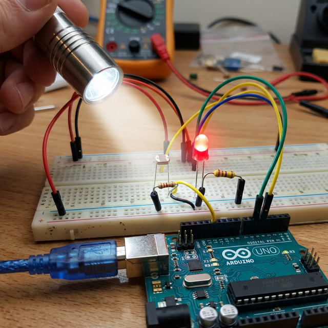
Needed Base Hardware
- Arduino Uno/Nano.
- One Cadmium-Sulfide (CdS) Photoresistor / LDR.
- One 10K Ohm Resistor (Required for the voltage divider math).