Connecting Flex Sensor With Arduino and Servo Motor
About Flex Sensor
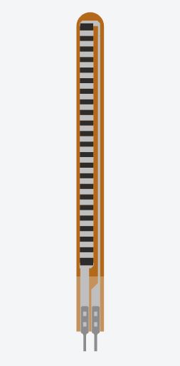
Flex sensor is a flexible resistor, it has two pins. Whenever you bend it, its resistance changes. Its resistance is minimum when it is relaxed or straight. And resistance is found maximum when bended.
It follows resistivity
ρ = RA/l
where ρ = resistivity of a material
R = Resistance
A = Area of the material
l = Length of the material
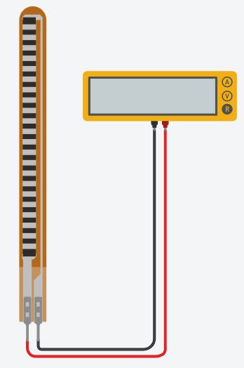
Measurement of Sensor Resistance
Connect the flex sensor to a multimeter, and set the multimeter on resistance.
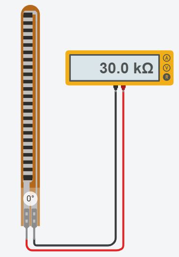
Note down its resistance when normal i.e. Straight ( bend angle = 0°)
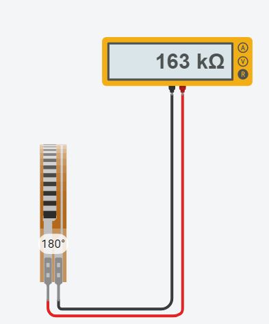
Note down its resistance when fully bend ( bend angle = 180°)
Now, its time to connect it with arduino board.
Connecting Flex Sensor With Arduino
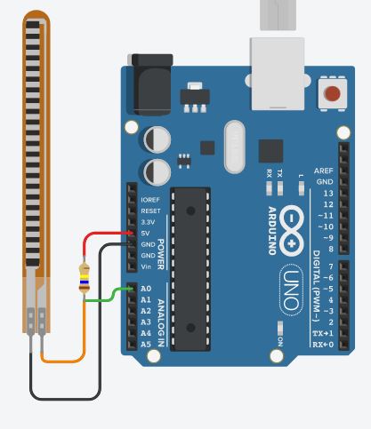
As the flex sensor is a variable resistor, we cannot connect it directly to arduino. We need a voltage divider circuit. The first resistor will be fixed one. The value of the resistor must be equal to the max resistance value of flex sensor. The fixed value resistor and flex sensor must be connected in series. The fixed value resistor must be connected to 5V whereas the flex sensor must be connected to GND. Their junction must be connected to pin A0 of the board.
Connecting Servo Motor
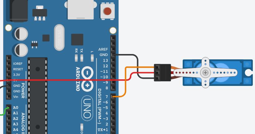
Servo motor has three pins Power, Ground and Signal power and ground needs to be connected to 5V and GND pins of board respectively. Signal can be connected to any of the digital pin.
Record the analog input value by bending the sensor from minimum to maximum.
The servo motor need angle in degrees from 0° to 180°, but the sensor data can be any value from 0 to 1024.
Use to the below code to convert the flex sensor value to proportional servo motor angle.
int const min_flex_val= 159 // analog input value for straight sensor
int const max_flex_val= 511 // analog input value for totally bended sensor
float flex_value = analogRead(A0);
float y= ((flex_value - min_flex_val)/(max_flex_val-min_flex_val));
int angle=(y*180); //angle value will be in the range 0 to 180
By doing above your motor should rotate proportionally to the bending of the sensor.
This can be used to control the hand of a robot, or mimic human hand gestures.
EXPANDED TECHNICAL DETAILS
Bio-Mechanical Kinesthetic Interface
This project mimics the movement of a human finger or limb by mapping the physical bending of a flex sensor to the angular position of a servo motor.
- Resistive Voltage-Divider Acquisition: The flex sensor's resistance changes as it bends. The Arduino captures this via a 10-bit ADC, mapping the 0-5V analog signal into a discrete "Bend Factor."
- Proportional Actuator Mapping: The firmware uses the
map()function to translate the sensor's raw range (typically 20k - 100k ohms) into a 0-180 degree servo sweep.
Accuracy
- ADC Noise Averaging: Includes a software "Running Average" filter. By averaging the last 5 readings, the Arduino prevents the servo from "Jittering" due to the electrical noise inherent in resistive sensors.