First of all we need to know what is meant by ultrasonic sensor ?
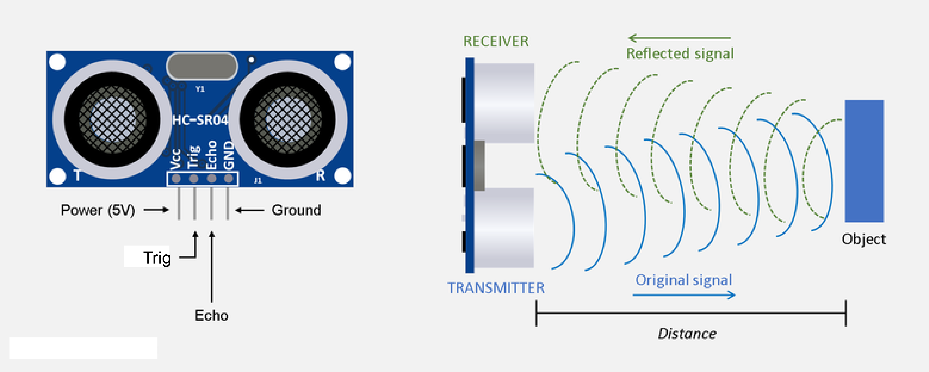
Ultrasonic sensor measures the distance of a target object by emitting ultrasonic sound waves, and converts the reflected sound into an electrical signal. Ultrasonic wave is defined as “inaudible sound with high frequency for human”. Ultrasonic sensors have two main components: the transmitter ( Trigger pin ) and receiver ( Echo pin ). Transmitters convert electrical signals into ultrasound, receivers convert ultrasound into electrical signals, and transceivers can both transmit and receive ultrasound. Ultrasonic sensor has four pins namely Gnd, Vcc, Trigger and Echo. Gnd is considered as the negative pin and is connected to the ground of the system. Vcc basically powers up the sensors typically 3.3 V. Trigger works as the transmitter and echo works as the receiver.
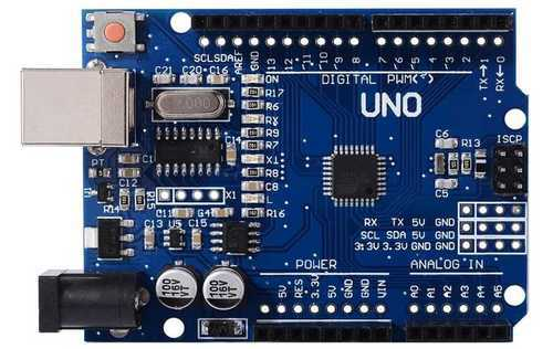
The Arduino Uno is a microcontroller board based on the ATmega328. It has 20 digital input/output pins (of which 6 can be used as PWM outputs and 6 can be used as analog inputs), a 16 MHz resonator, a USB connection, a power jack, an in-circuit system programming (ICSP) header, and a reset button.
In the simplest terms, a light-emitting diode (LED) is a semiconductor device that emits light when an electric current is passed through it. Light is produced when the particles that carry the current (known as electrons and holes) combine together within the semiconductor material. Led has two terminals : positive and negative.
A buzzer or beeper is an audio signaling device, which may be mechanical, electromechanical, or piezoelectric (piezo for short). Typical uses of buzzers and beepers include alarm devices, timers, and confirmation of user input such as a mouse click or keystroke. Buzzer has two terminals : positive and negative.
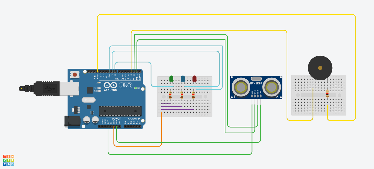
Now we can start working on the circuit :
Ultrasonic sensor connections -
Vcc to 3.3 V of Arduino Gnd to Gnd of Arduino Trigger to digital pin 1 of Arduino Echo to digital pin 2 of Arduino
Led connections : Negative terminal of the Led should be connected to one led of resistor. And the other leg of resistor should be connected to Gnd of Arduino.
Led no 1 positive terminal to digital pin 10 of Arduino Led no 2 positive terminal to digital pin 9 of Arduino Led no 3 positive terminal to digital pin 8 of Arduino
Buzzer connections : Positive terminal of buzzer to digital pin 3 of Arduino. Negative pin to one leg of resistor. Another leg of resistor to Gnd of Arduino.
Refer the circuit diagram for better understanding :
The circuit diagram is uploaded in the hardware section. Here is the code for the project :
int trigPin = 1;// Trigger pin of Ultrasonic sensor to digital pin 1 of Arduino.
int echoPin = 2;// Echo pin of Ultrasonic sensor to digital pin 2 of Arduino.
int buzzer = 3;// Buzzer positive terminal to digital pin 3 of Arduino.
int LED1 = 10;// Led 1 positive terminal to digital pin 10 of Arduino.
int LED2 = 9;// Led 2 positive terminal to digital pin 9 of Arduino.
int LED3 = 8;// Led 3 positive terminal to digital pin 10 of Arduino.
long duration;
int distance;
void setup()
{
pinMode(trigPin, OUTPUT); // Leds and buzzer is output here. // Arduino and Ultrasonic sensor is input here.
pinMode(echoPin, INPUT);
pinMode(LED1, OUTPUT);
pinMode(LED2, OUTPUT);
pinMode(LED3, OUTPUT);
digitalWrite(LED1,LOW);
digitalWrite(LED2,LOW);
digitalWrite(LED3,LOW);
Serial.begin(9600);
}
void loop() {
digitalWrite(trigPin, LOW);
delayMicroseconds(2);
digitalWrite(trigPin, HIGH);
delayMicroseconds(10);
digitalWrite(trigPin, LOW);
duration = pulseIn(echoPin, HIGH);
distance= duration*0.034/2;
if(distance<=10){
 digitalWrite(LED1,HIGH);
 digitalWrite(LED2,HIGH);
 digitalWrite(LED3,HIGH);
 tone(buzzer, 2500);
}
else if (distance<=20){
 digitalWrite(LED1,HIGH);
 digitalWrite(LED2,HIGH);
 digitalWrite(LED3,LOW);
 tone(buzzer, 2500);
 delay(50);
 noTone(buzzer);
 delay(50);
}
else if(distance<=35){
 digitalWrite(LED1,HIGH);
 digitalWrite(LED2,LOW);
 digitalWrite(LED3,LOW);
 tone(buzzer, 2500);
 delay(250);
 noTone(buzzer);
 delay(250);
}
else{
 digitalWrite(LED1,LOW);
 digitalWrite(LED2,LOW);
 digitalWrite(LED3,LOW);
 noTone(buzzer);
}
Serial.print("Distance from the object = ");
Serial.print(distance);
Serial.println(" cm");
delay(1000);
}
.
EXPANDED TECHNICAL DETAILS
Fundamental Sonar Ranging Logic
A technical deep-dive into the physics of sound-travel and distance measurement in the Arduino ecosystem.
- Time-of-Flight (ToF) Calculation: The Arduino triggers a 10µs pulse from the HC-SR04 trigger pin. It then captures the exact microsecond duration of the incoming echo pulse. The formula $(Duration imes 0.034) / 2$ is used to derive the distance in centimeters.
- Non-Blocking Ranging: (Advanced version) Uses the
NewPinglibrary, which utilizes timer interrupts instead of busy-waiting, allowing the Arduino to perform other tasks (like updating a display) while waiting for the sonic echo.
Hardware Hub
- Signal Filtering Matrix: Implements a "Median Filter" that takes 5 consecutive pings and ignores outliers, ensuring a stable and noise-free distance readout for robotics or security applications.