I needed to setup a cheap kit - due to COVID-19 - for an oscilloscope for a basic physics course (LCR circuits) at a public-and-free university so that the students could work from home. Never having used an Arduino, but decided to go this way, I found the nice project of Veldekiaan. But, I needed to study resonances and L/R time constants for inductors that would plug into a small protoboard: thus I needed higher speed than his original project while keeping reasonable accuracy. I then modified his code (this project heavily borrows on his) and added an interleaving sampling at the fastest scale (100µs/div), reaching a 3µs time resolution. I also added a "Save Channel" option in his "Processing" sketch, so that the students could treat and fit the data externally. For the connections proposed the "Counter" does not work. The software implementation I made is a quick fix to get this working, maybe not portable, and certainly it is not optimized. This is my first post here and I do not have much time to logon here or answer questions: sorry. I may do that occasionally. But I think this is a nice extension of Veldekiaan's work that will be useful for many people.
EXPANDED TECHNICAL DETAILS
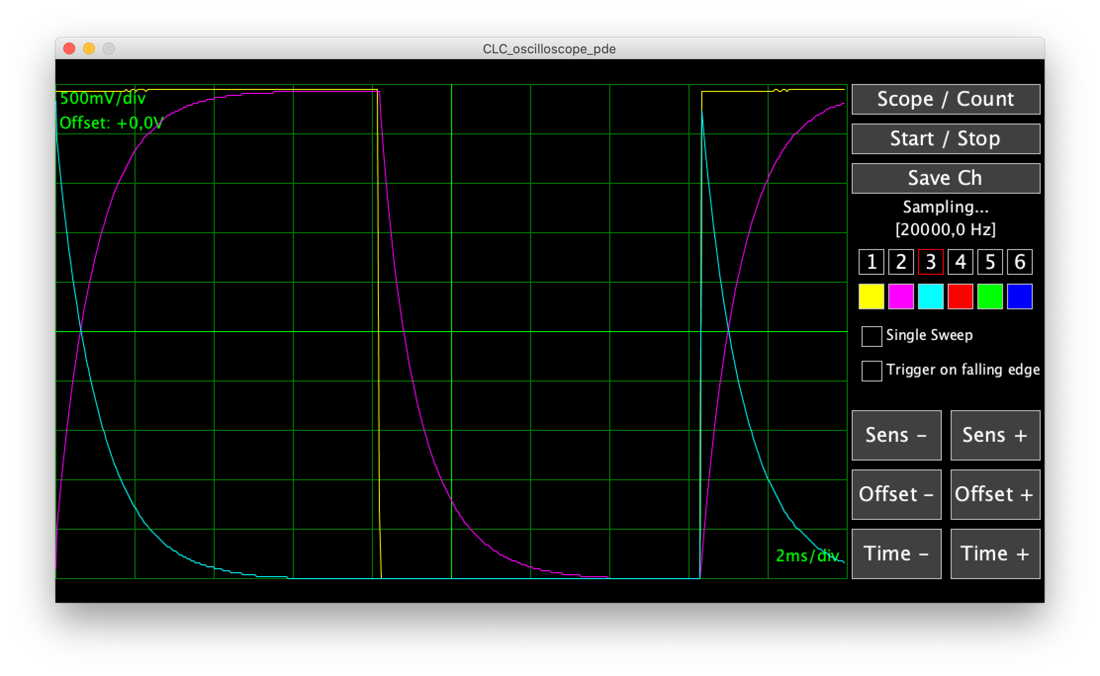
High-Speed Sampling Hack
Standard Arduino Uno sampling is too slow for 20kHz waves. This "Interleaving" technique pushes the hardware beyond its documented limits.
- ADC Interleaving Logic: The Arduino samples the signal multiple times, but each time it delays the start by a tiny bit (a few microseconds). By stitching these "slightly shifted" captures together, it creates a much higher effective sampling rate.
- Direct Port Manipulation: To achieve this speed, the firmware bypasses the slow
analogRead()function and communicates directly with the ADMUX and ADCSRA registers, reducing processing overhead to near-zero.
Visual Output
- Processing Display: The high-frequency data is visualized on a PC using Processing, providing a clear 20kHz sine or square wave display that would normally require mid-range specialized hardware.