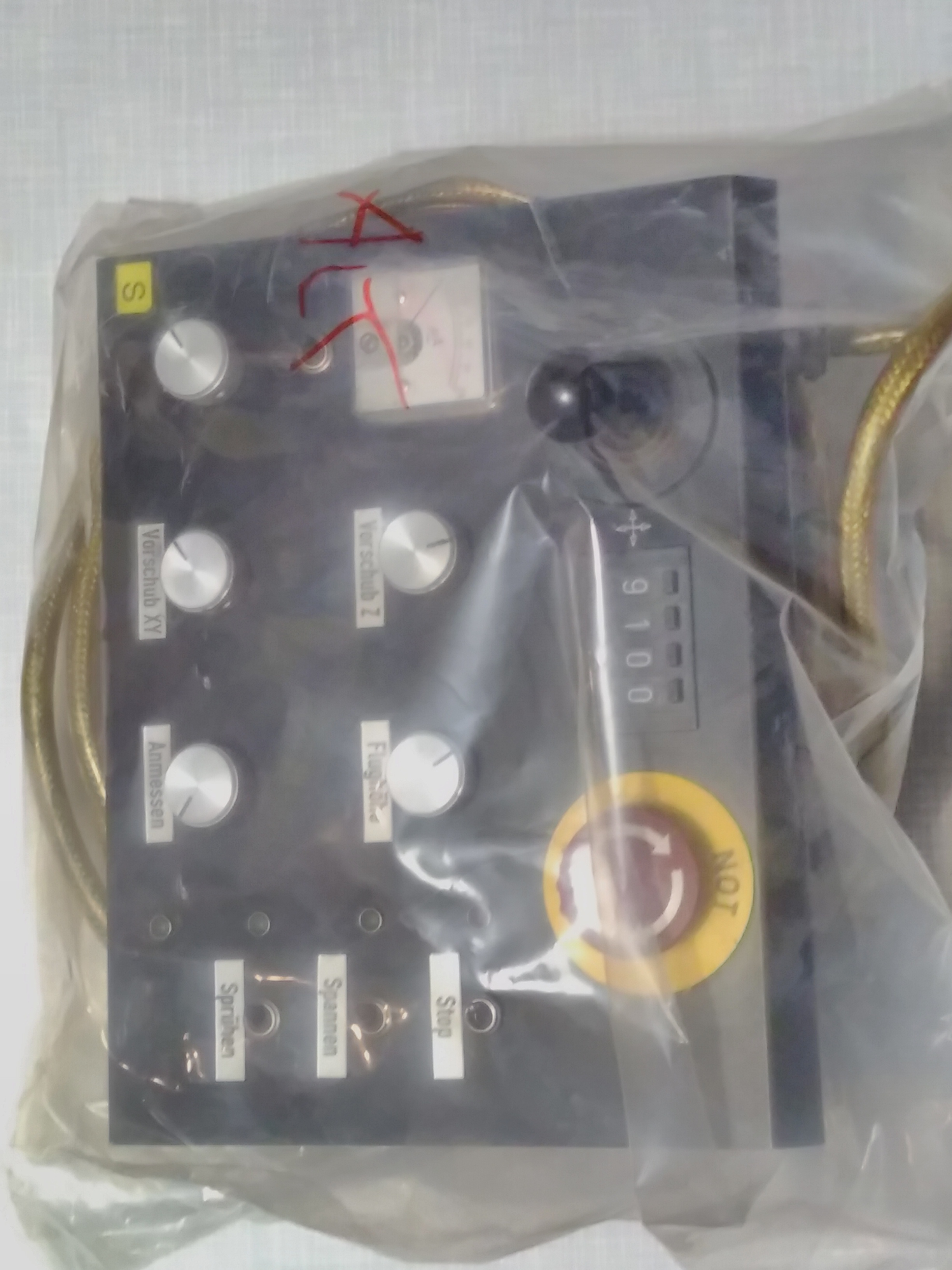
With my nephew's birthday around the corner, I found this scrap control panel and decided to make him a busy board out of it:
How it works
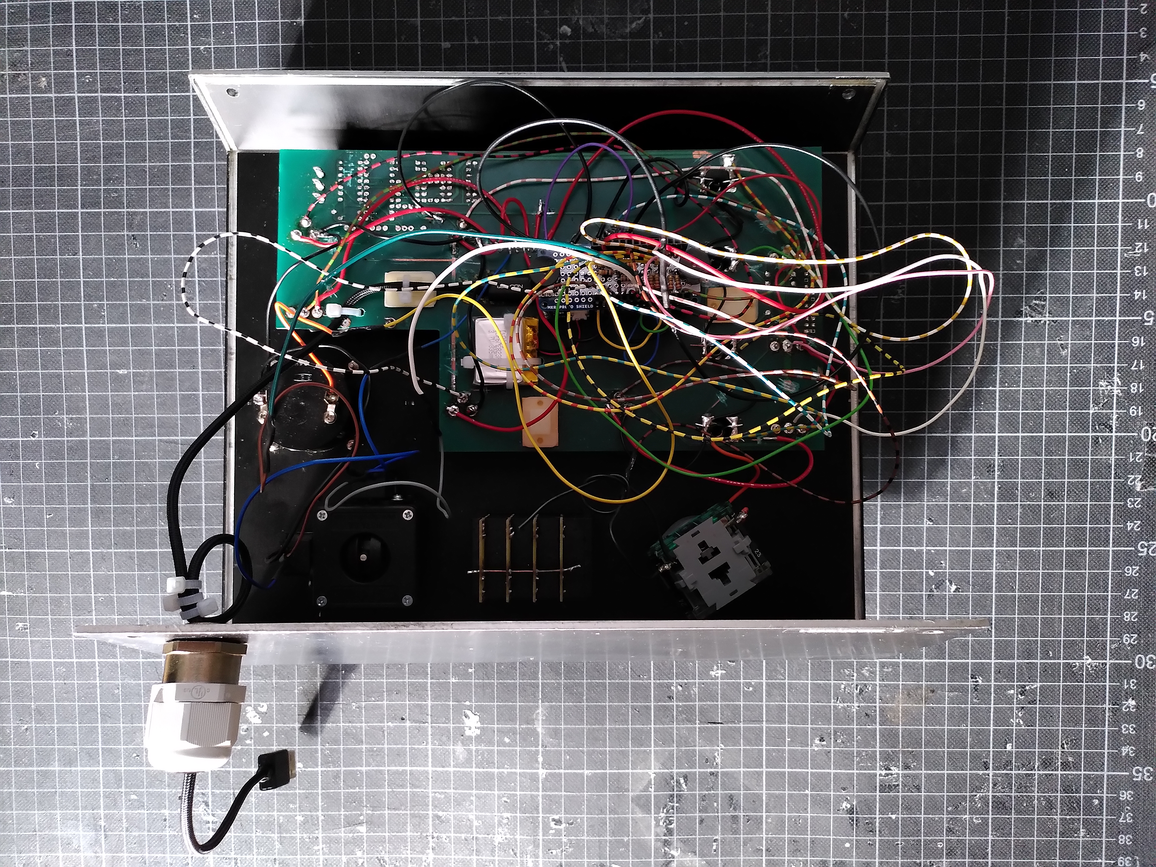
The Arduino board needed a battery connector and WiFi to be able to mute the sound via the Arduino IoT Cloud Remote App. Accordingly, I decided to use an Arduino MKR WiFi 1010. Since I didn't have much time to analyze the layout of the old PCB, I cut the traces connected to the buttons, switches and LEDs in order to prevent any unplanned behavior. Then I soldered the power, ground and I/O wires from the components to a MKR proto shield. To charge the battery and to physically connect to the board, a USB cable is plugged into the Arduino and leads out of the enclosure.
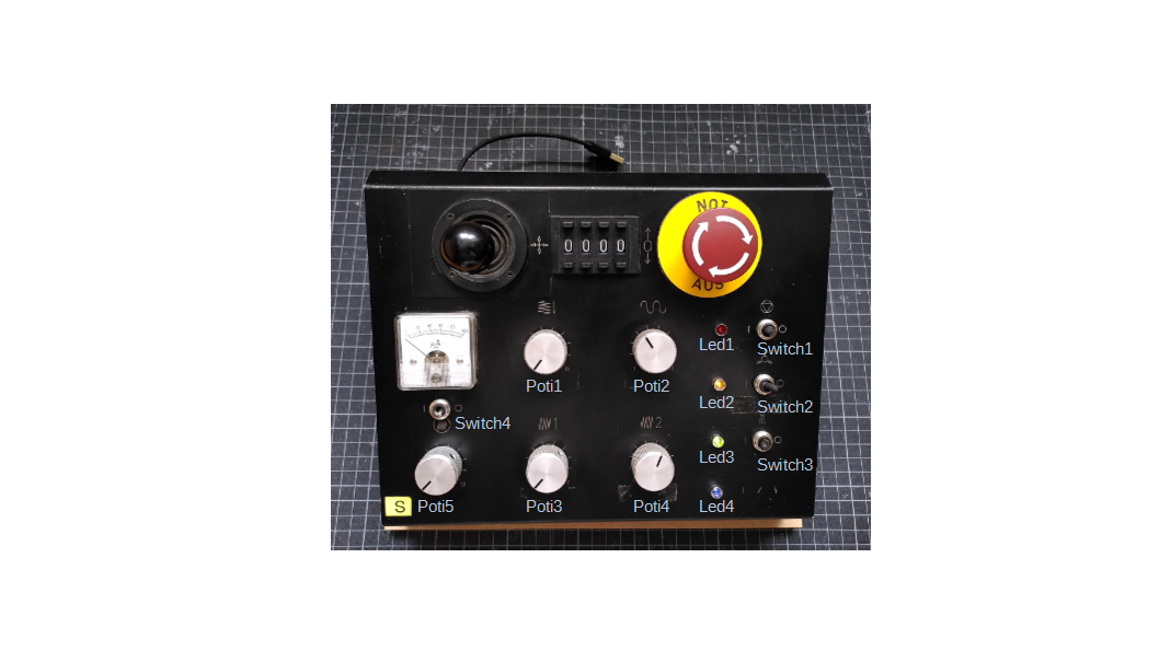
The analog inputs of the joystick's x- and y-axis as well as potentiometers 1 and 3 control the two buzzers (duration of tone/pause and frequency).
Switches 1 and 3 select whether LEDs 1 and 3 are dimmed or blink. Both (brightness for dimmimg and interval for blinking) are controlled with potentiometers 2 and 4.
Switches 2 and 4 simply turn LEDs 2 and 4 on and off. Potentiometer 5 controls the gauge and the emergency stop button resets the Arduino when pressed.
A little twist
Why put a limit to creativity with inputs always leading to the same outputs? Activating the random mode on the IoT Remote App re-assigns the inputs (switches, potentiometers) to the outputs (LEDs, buzzers, gauge) using the random function and thereby breaks the strict assignement.
Nerd fact:
In the tone() reference it says "Only one tone can be generated at a time". That is certainly true, however, two buzzers can beep in between each other and it almost sounds like they beep at the same time.
Learnings:
what would I change if I did it again?
- the Li-Po battery is way too small (it was actually intended for another project). In the guide to powering a MKR WiFi 1010 with a battery, a minimum of 1024 mAh is recommended.
- once the bottom half of the case was attached, the buzzers were not as loud as they were out in the open - in fact even pretty quiet. Next time I would definately use louder buzzers or even speakers.
- the emergency stop button ("Not Aus") is wired to the reset pin of the Arduino. Unfortunately the punchable big red button catches lots of attention, which leads to the rest of the functions being turned off some of the time. Changing this function in the software would be much easier than soldering.
- the wiring is a mess. Using some of the traces in the generic PCB probably would have led to a cleaner look.
EXPANDED TECHNICAL DETAILS
Interactive Educational Hub
The IoT Busy Board is a multi-modal tactile learning tool designed to teach children (and adults) about hardware interfaces and cloud connectivity.
- Multi-Sensor Interaction: Features a variety of inputs: a rotary potentiometer, a 4x4 matrix keypad, and several toggle switches. The Arduino captures these physical inputs and creates corresponding visual or acoustic feedback.
- Arduino IoT Cloud Sync: Every physical action (e.g., flipping a switch) is mapped to a "Cloud Variable." This allows parents or teachers to see the board's status in real-time on a smartphone dashboard.
Feedback Actuators
- Multi-Output Drive: The board manages a NeoPixel ring (for color theory), a piezo buzzer (for music), and a small servo motor (for physical movement), providing an all-in-one platform for exploring electronics.