Introduction
I wanted to do a walking four legged robot, more in a "mammal" style than the normal "spider" or "insect." The inspiration comes from the well known Boston Dynamics robots and other four legged research robots. Making a robot like this is quite challenging since it quite easily tips over due to a high center of gravity and the feet under the body instead of spreading out to the corners.
The aim was to build a cheap robot, using Arduino and low cost micro servos. This solution of course has it's limitations. One can not expect it to be perfect but I have manage to build a few robots now that can perform the walking behavior as described in this film. And doing the best one can on a very small budget is a challenge by itself and maybe something guys on heavily funded research projects never have to face . :)
It was early identified that a study of inverted kinematics (IK) was needed in order to get it right. The code has a set of equations to calculate joint angles based on desired foot movements. These can be further used in functions for some recurring tasks like doing a body movement (moving all fours feet in the opposite direction) and making a complete foot movement (lifting upwards moving in a specified direction and putting it down again).
The Massive Inverse Kinematics (IK) Problem
Programming a robot using 4 physical legs (8 dedicated Servo Motors) to mathematically lift, carry, plant, and propel its mass continuously while maintaining the absolute physical center-of-gravity without falling over requires complex spatial calculus. The controller must dictate exactly 8 independent servo angles in complex, non-linear floating-point waveforms simply to execute a single, rudimentary "Walk Cycle."
If you command ShoulderServo.write(45) and KneeServo.write(45), you are doing "Forward Kinematics." The foot arbitrarily lands somewhere in the dirt.
- The KITtyBot cannot operate blindly. It uses Inverse Kinematics.
- The Arduino code states: "I want the foot to be exactly at
X=10mm,Y=50mmon the Cartesian graph." - The C++ code forces the processor to execute geometric Trigonometry!
// Explicit Inverse Kinematics calculating the Knee Angle based entirely on exactly where the foot must land!
float calculateKneeAngle(float x, float y) {
  float distance = sqrt(sq(x) + sq(y)); // Absolute Pythagorean theorems inside the ATmega!
  // Heavy ACos mapping resolving dual-link arm matrices!
  float angle = acos((sq(femurL) + sq(tibiaL) - sq(distance)) / (2 * femurL * tibiaL));
  return (angle * 180 / PI); // Radians mathematically converted to physical Servo degrees!
}
The next challenge is to do gait studies, i.e. to define how the robot should walk and turn in terms of body and foot movements. My robot uses statically stable gaits all the time. One foot at the time is lifted and put into a new position. The body rests on the other three feet and in order to not tip over the center of gravity must remain within the tripod that these feet form. I developed four standard gaits - forward, reverse, left and right. This in turn utilizes the foot and body movement functions to be combined into a full sequence.
I also designed a function for synchronous servo movements. In some cases several servos are making different strokes during a set time. This must be synchronized in order to achieve smooth movements.
The Hardware Execution
An Arduino cannot cleanly drive 8 servos. The internal timers can shatter under intense PWM demand, causing the robot to randomly jerk and collapse ("Jitter").
- The PCA9685 Execution Engine: The Arduino can outsource the entire PWM workload!
- The Arduino connects via
I2C (SDA/SCL). It transmits the desired angle integers to an external Adafruit 16-Channel PWM Servo Driver chip. - That external chip natively, independently pulses all servos simultaneously with zero calculation overhead demanded from the Arduino, ensuring the quadruped executes the walking gait completely seamlessly!
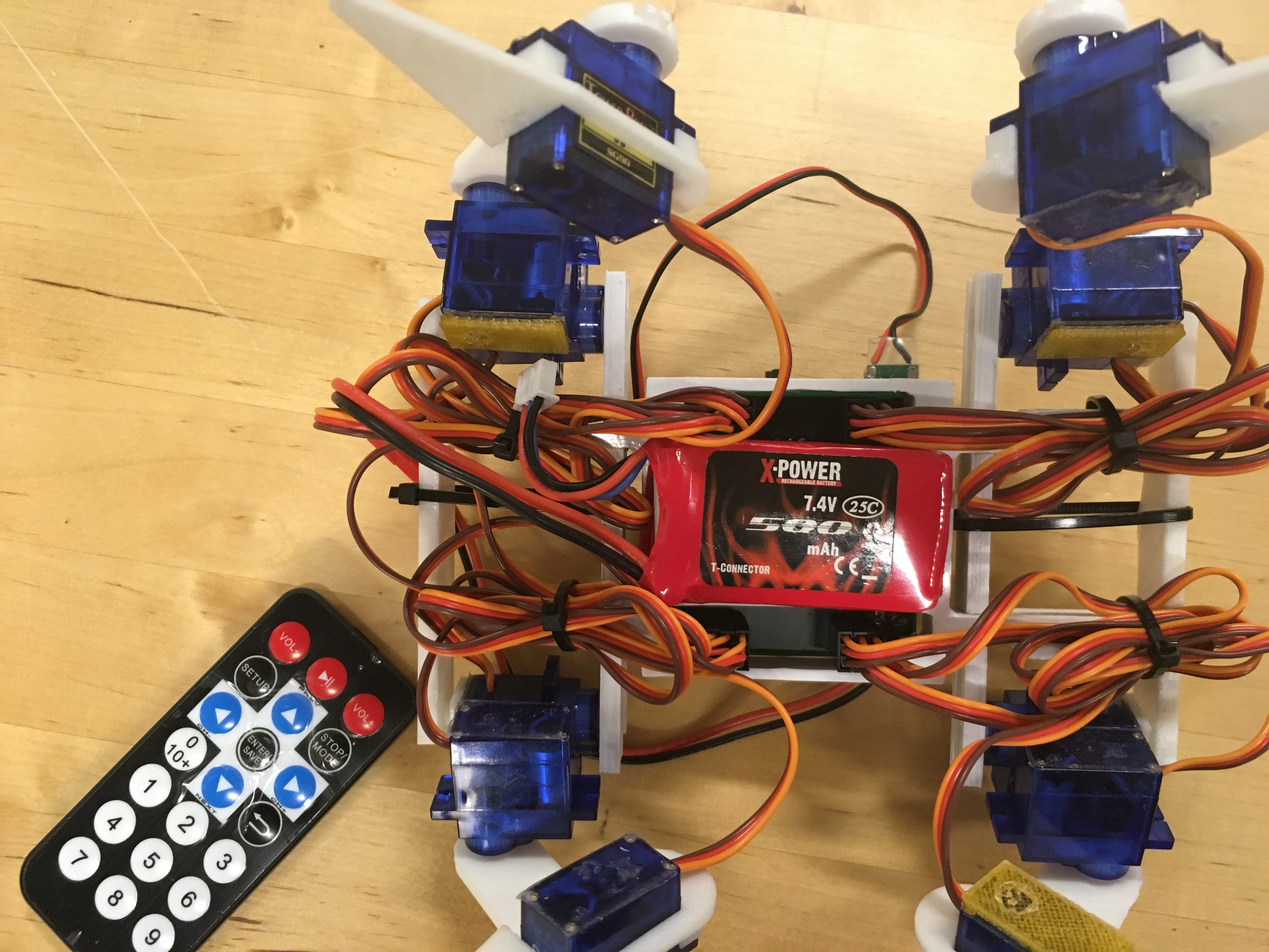
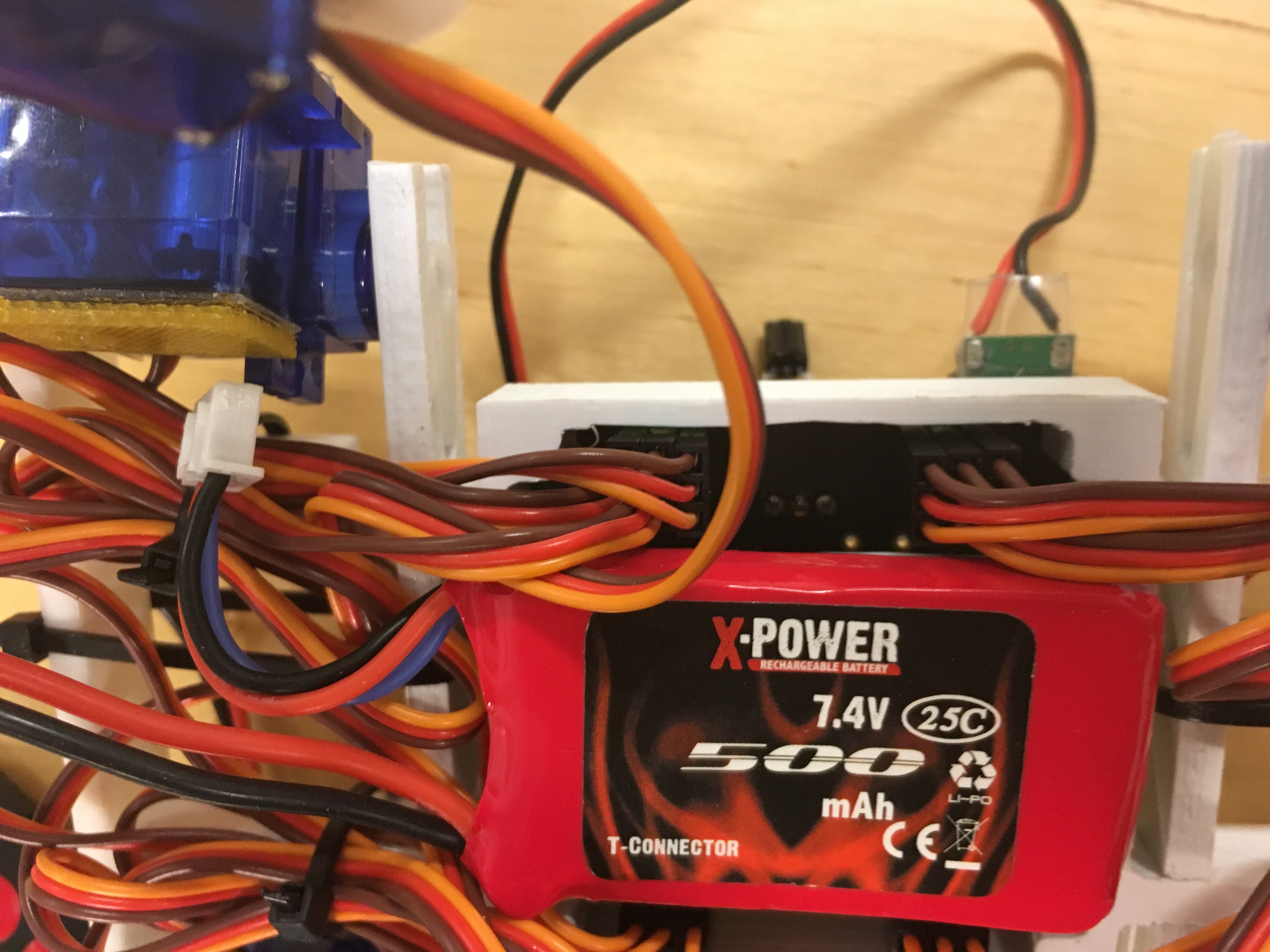
Last but not least i use a completely unprotected LiPo battery. This can be risky, the major hazards is to dis-charge it to fast or too deeply. The first hazard is avoided as long as it isn't accidentally short-circuited. A normal R/C battery has a discharge rate of 25 C which in this case allow for 12 A. The UBEC will prevent it from being higher than 2 A in any circumstances. The second hazard is prevented by a surveillance function in the software. The voltage is measured on one of the analog pins and if gets lower than 7.0 V the robot is put to rest.
And finally I must stress that the batteries should be charged with a purpose built charger and handled with usual care, never leave charging unattended. The battery should detached from the robot (use velcro to mount it) and charged inside a fire proof bag or at least with a safe distance from flammable materials so a fire can be contained and not spread. Also store your batteries safely.
If you are not familiar with LiPo batteries consult a local R/C hobby store and buy batteries together with a suitable charger and possibly a fire proof bag/container for charging and storage. These items are often full of warning signs. Reda them and use your own good judgement. :)
Building the robot
Print the parts according to the supplied files. Take som time to look at the pictures and figure out how to assemble the parts before starting. I am Scandinavian but this instruction is far from the level of an IKEA or LEGO instruction :)
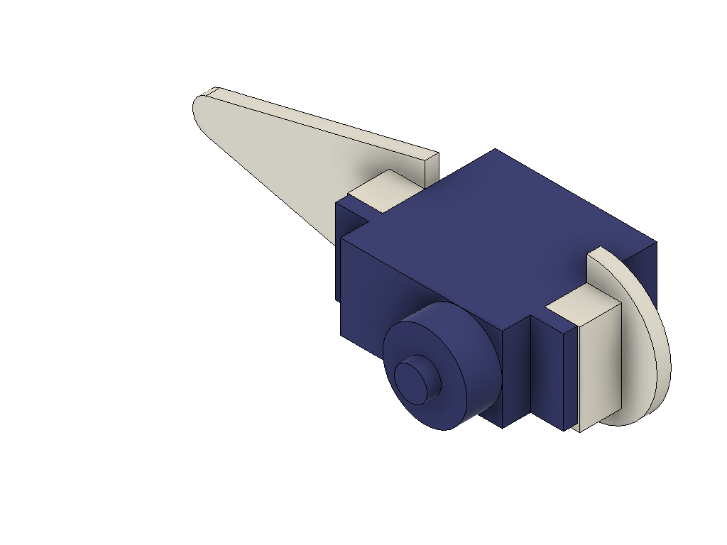
The hip joint should be assembled first. I used double sided tape of good quality to join the parts. They could be glued also but in case there would be a need to repair a broken part they are impossible to disassemble, one broken servo leads to a replacement of the complete joint.
Put the servo support on the bottom of one servo, in line with the actuation axis. Then join another servo with it's axis perpendicular. The picture below shows the hip joint for the front-right and rear-left. For the two other corners mirrored joints should be made.
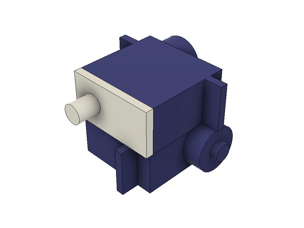
Before proceeding it is good idea to make sure that all 12 servos are centered. The best way is to assemble the PCB (or breadboard, see below), connect all servos and the load the code. When the Arduino is started up all servos will center (command signal 90 degree). There will be need to fine tune the center positions later once the robot is assembled.
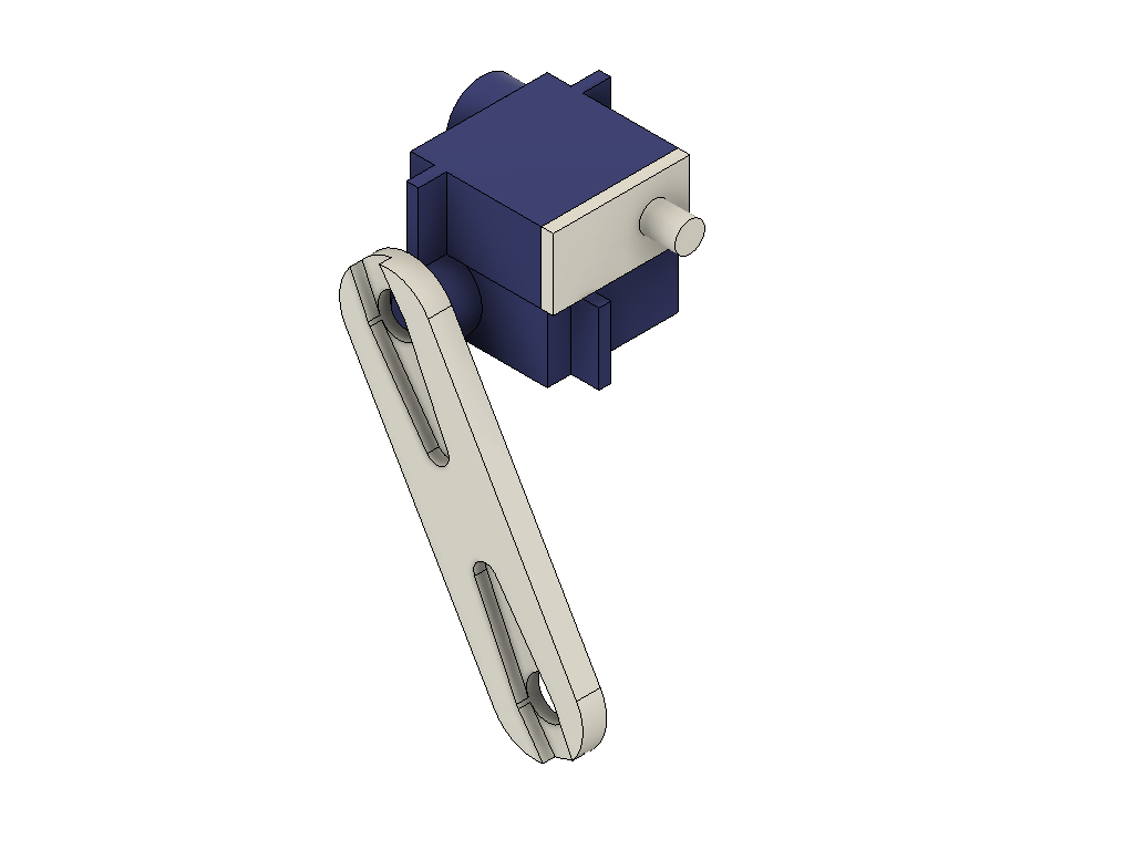
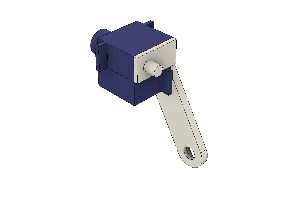
The next step is to attach the part called thigh, the "upper limb" of a leg assembly. This part has recesses that fit together with the servo horns that normally is delivered together with the servo. Glue horns into the recesses. Make sure to use a glue that works for joining the 3D printed material and the nylon plastic that the horn is made of. The glue gun I used worked fine, I have had some mixed success with CA glue though (some brands work, other not).
The thigh is joined to the hip joint at a 60 degree angle. Try to find a position that comes as close as possible to this angle when the servos have been centered. Secure the horn onto the servo spline with the supplied screw (often the shorter of three that are delivered with a servo). Below are two pictures of assembled thigh and hip, servo horn not included for clarity (or never modelled out of laziness from my side) .
The lower part of the leg should also be assembled. In this case a servo is attached to the leg part using screws. There are screws supplied with the servo (often two longer "wood" screws).
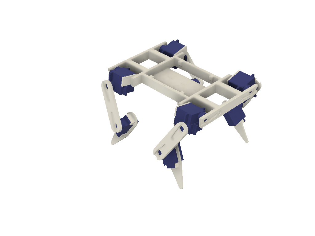
Now the legs can be assembled onto the body. There are two parts I called "bumper" that are on the front and rear of the robot (like the bumpers on a car). They have recesses for servo horns just like the thigh part. Glue horns into them. Then slide the servo support of an upper leg into the corresponding hole in the body. When this is done on both sides, the assembly can be secured by the bumper. Allow the legs to point out at about 12 degrees (a 20 mm toe-out of the leg). The bumper is secured to the body by using left-over (longer) servo screws.
At last the lower legs of the robot can be attached. They should be angled in the opposite direction of the thigh, making the tip of the foot being right under the hip joint of each leg assembly.
By this the robot is assembled. It should look like on the picture below. Note that the design of the robot has changed slightly compared to the top image and the film clip. The body has been redesigned to simplify and make a more robust design. The servo support and horn for the hip joint have swapped places. So assemble according to the 3D images and avoid being confused by the photos and film clips.
Of course the angles of each joint cannot be exactly at the angles required, the number of splines on a SG-90 servo is 21, leading to an angle of 17 degree between two positions. You can at best assemble the robot within 10-20 degrees, the remaining error must be adjusted by changing the neutral position in the code, see further down in this instruction. It might be a good idea to once again connect all servos and fire up the Arduino and check the neutral positions and if needed do some mechanical adjustments (moving a joint a spline or two). One tend to accidentally turn the servos when working with them.
Connecting the electronics
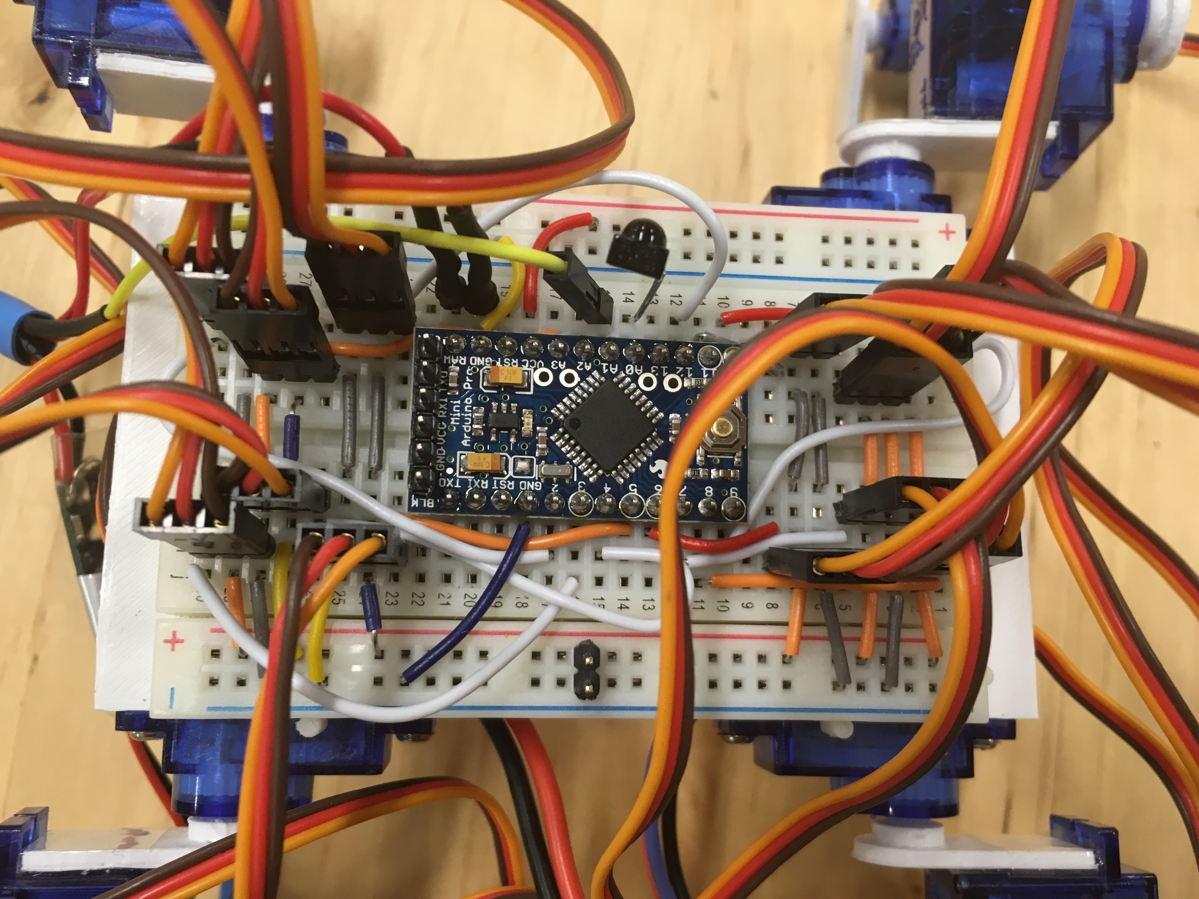
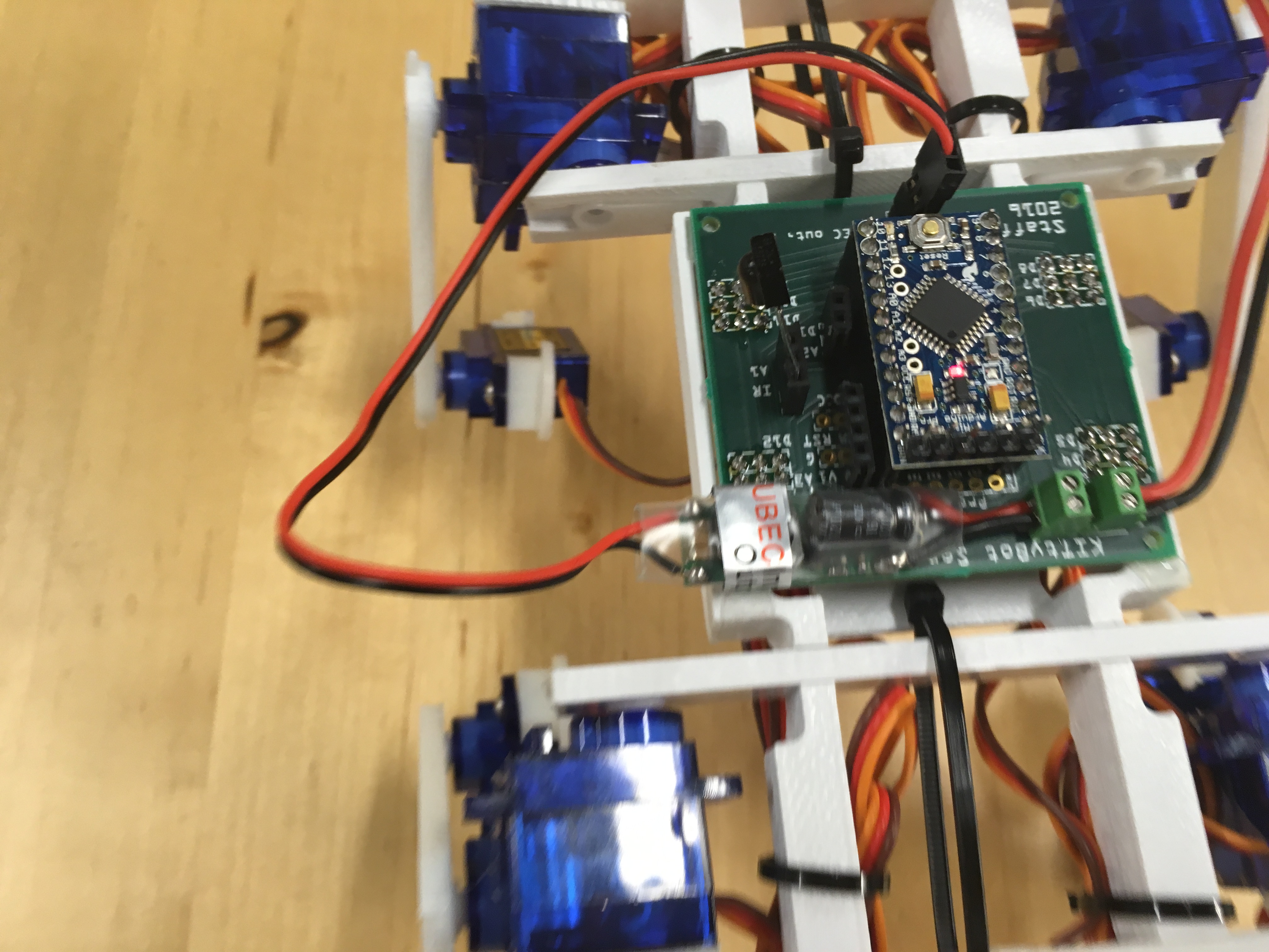
There are two options, have everything on one breadboard or to produce a PCB with the supplied Fritzing file. You might run into some problems with voltage in the breadboard if you don't take care when connecting all power and ground lines to the servos. In extreme cases one servo can consume 600 mA and poor connections lead to erratic behavior. The PCB have very broad copper traces for the power lines so if you just solder properly it will work fine.
There is no power switch in my design. The robot is simply turned on and off by connecting the battery. If you want to add one it should be after the battery connector, cutting of the 7.4 V supply to both the Arduino and the UBEC.
Breadboard version
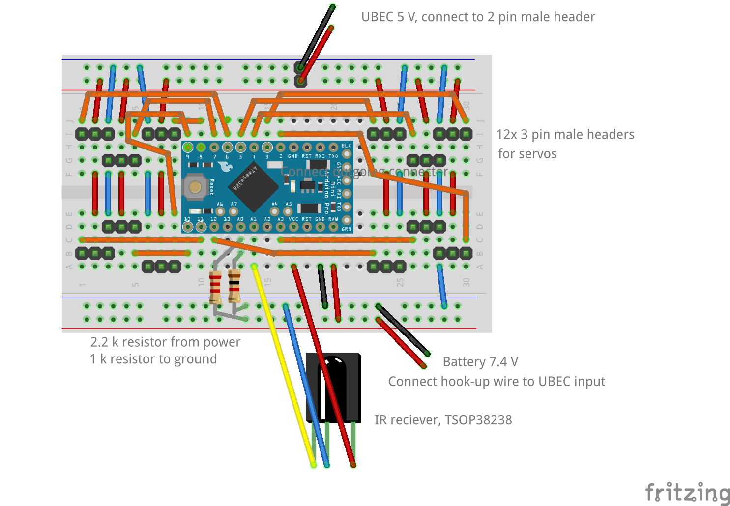
It is possible to have the Pro Mini, connectors for the servos and most of the other electronics on one half-size breadboard. I draw the schematics in the picture below. Make sure to use short jumper wires, especially for the 5 V power and ground connections to the servos. The servo connectors are simply extra long male headers that are cut in pieces of three and pressed into the breadboard.
What is not shown in the picture is the battery and the UBEC. There might be some soldering to fix this in order to attach a connector fitting to the battery. From the connector two jumper wires should be connected to the lower "power rail" of the breadboard in order to feed the Pro Mini (connected to RAW and GND). Also connect two resistors from the 7.4 V supply to the A0 pin. 2.2k goes from the positive side and 1k from the ground. This will divide the voltage, which is more than 8 V on a full battery, to a value below 5 V which can be measured by the analog pin.
The output side of the UBEC has a servo connector. It is quite convenient to add a two male header on the upper "power rail". Put it somewhere in the middle like in the picture to assure that the power distribution to the servos is as balanced as possible.
The IR receiver should be connected to A1 and have 5V supply. The pins on the receiver are long enough to be fitted into holes directly on the breadboard.
There is a schematic below and a picture on how the finished breadboard might look. Note that the picture shows an older version of the robot with different pinouts and connections. It still gives an idea on how to connect jumper wires and servo connectors.
The breadboard is attached to the body with its self-adhesive backside. Orient it so that the corner with the servos connected to the pins D3, D4 and D5 (upper right in the schematic) is on the front/left corner of the robot and make sure that the board is centered on the body (correct center of gravity is vital).
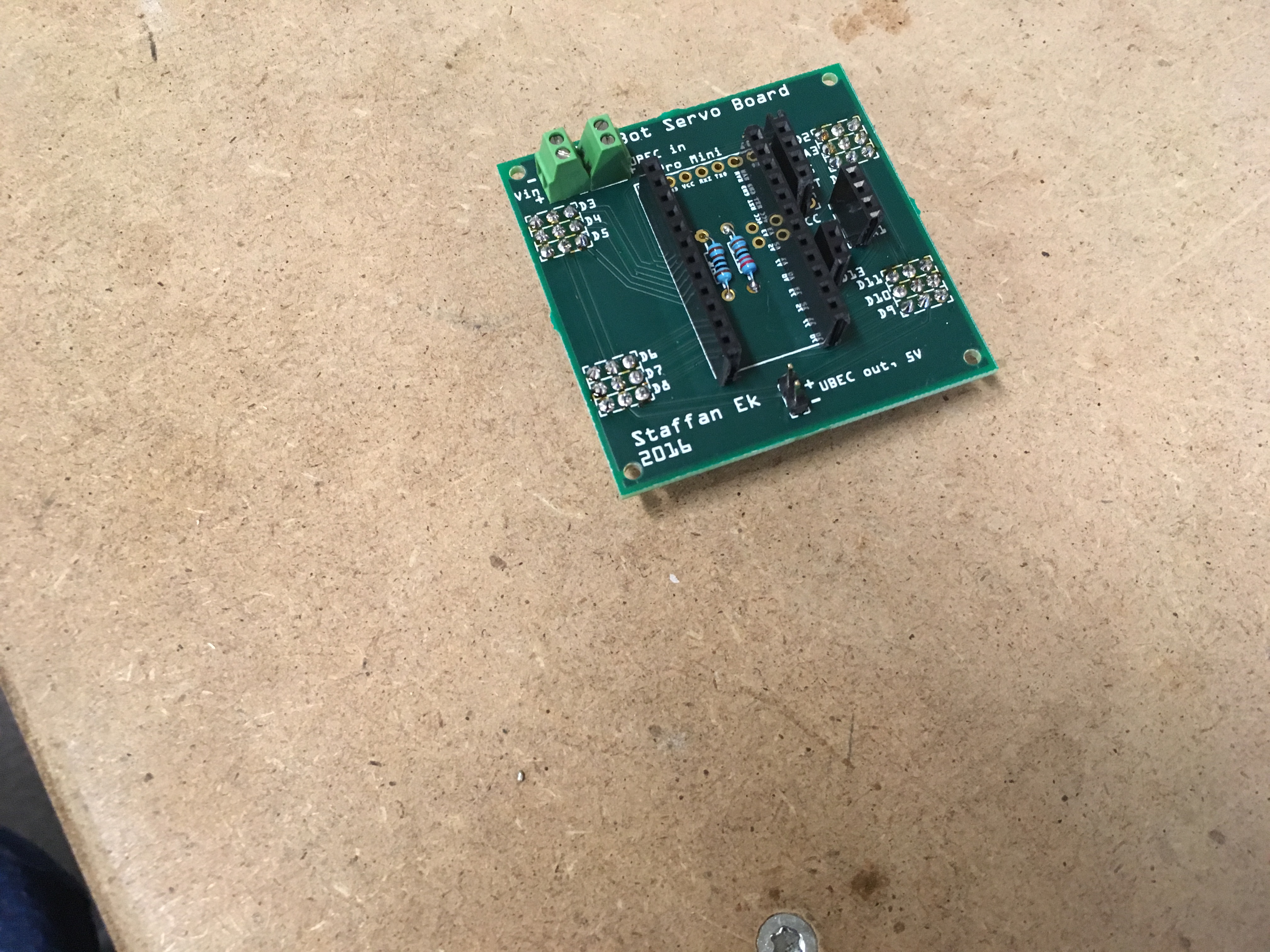
PCB version
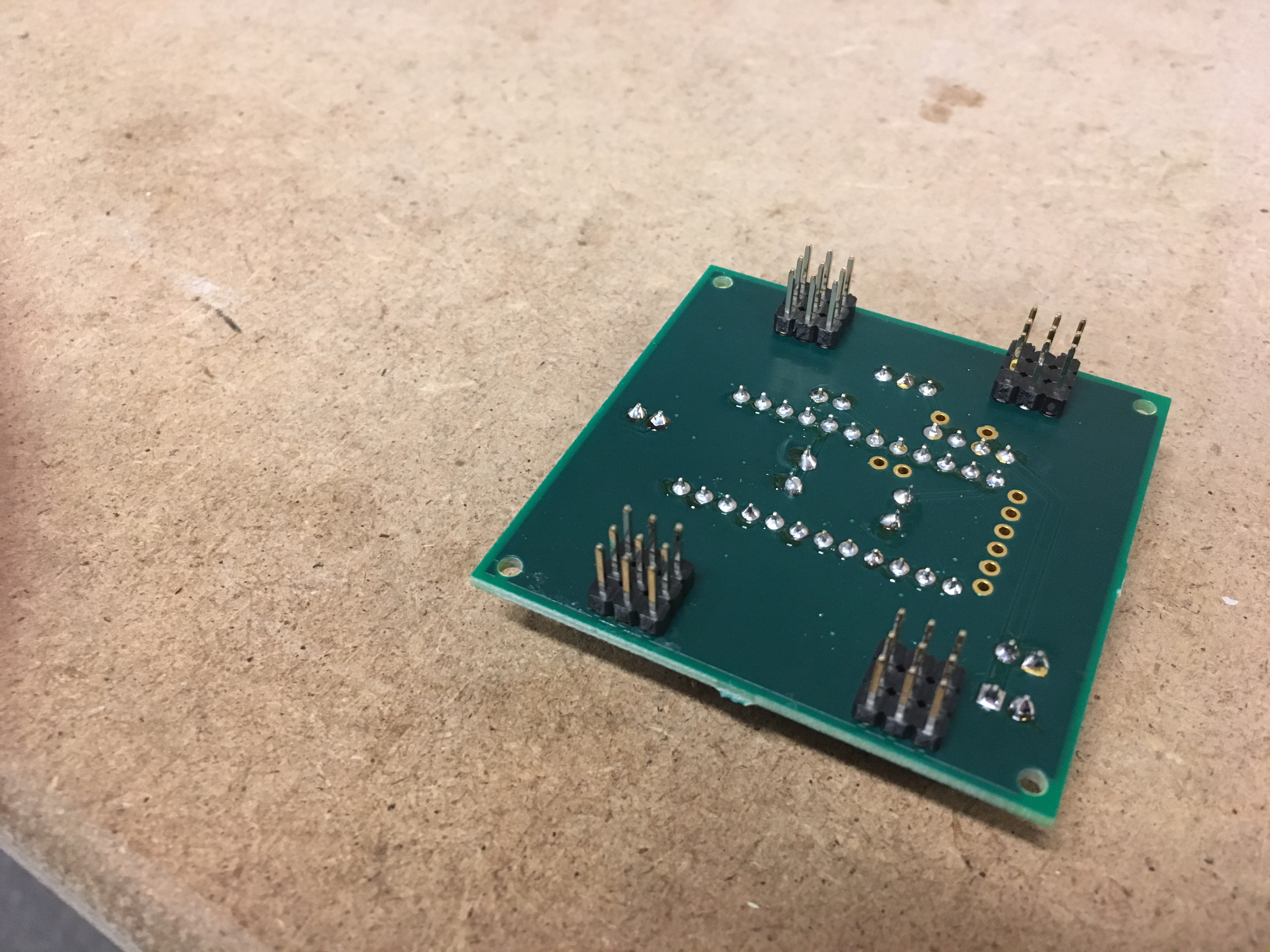
I added a Fritzing file below. This can be used to produce a PCB, either by ordering from the service available at Fritzing or by exporting files for PCB manufacturing. I did a serie of pictures to show the assembly below. The PCB is custom made for this robot with connectors to all servos, IR and voltage measurement. But there are also connectors broken out from the remaining pins. These can be used to connect other equipment if you want to expand the robot in the future.
There are small "pads" on the body the fits to the corners of the PCB. Also here the corner with the D3 to D5 connector should be on front/left. There are mounting holes on the PCB but I only used a piece of double sided tape on the body to attach it. It will stay on place.
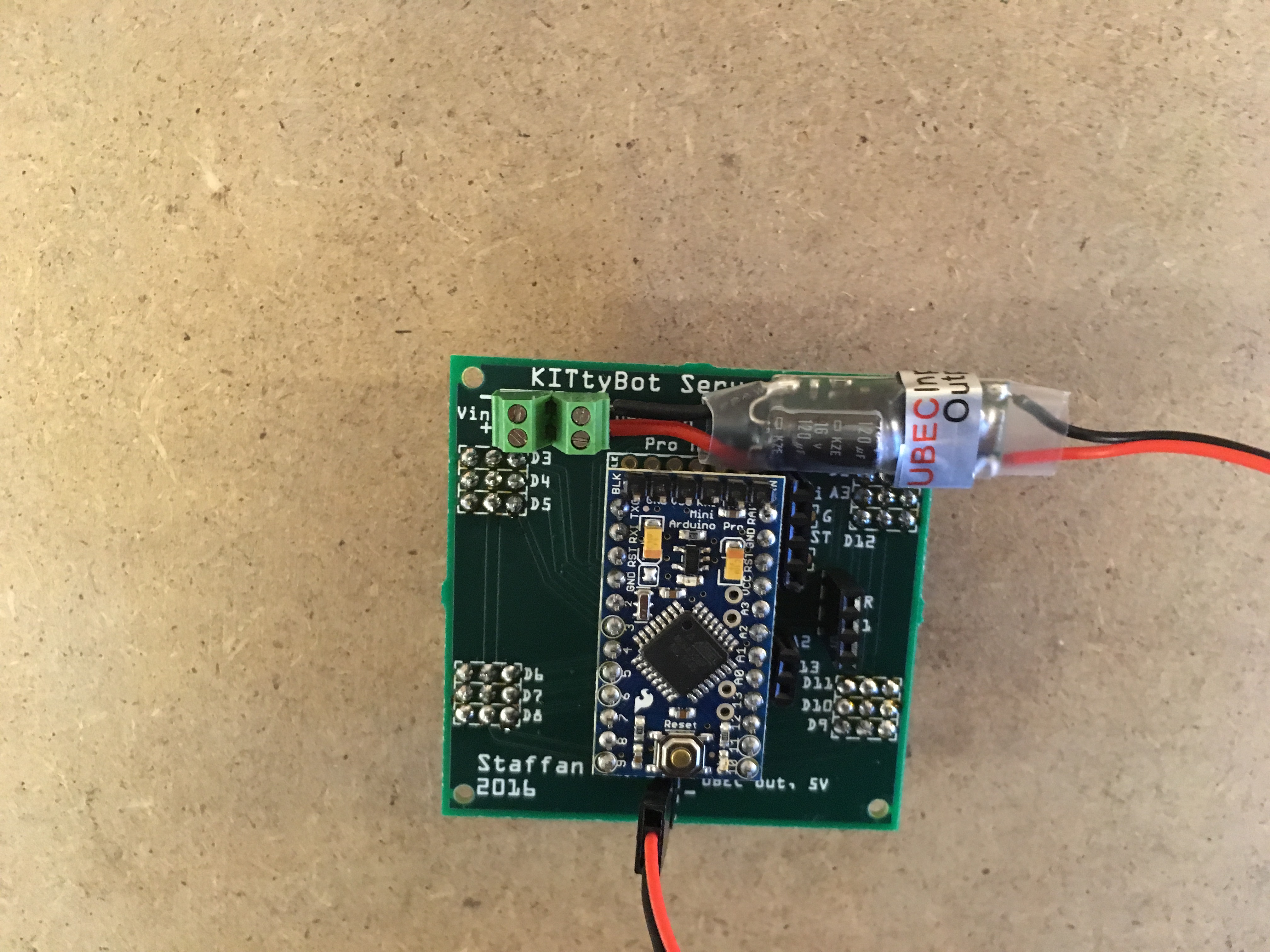
Battery
The battery is attached to the underside with velcro. There is flat surface dedicated for this on the body. A 7.4V/500mAh LiPo battery normally has the form factor of about 55x30x10 mm (give or take of few mm) and it fits quite well into this place.
Finally the robot can be "touched up" by strapping the servo wires into nice bundles so it isn't tripped by them while walking. It also gives the robot a nice look of actually being a four legged creature walking around and not a heap of servo wires. :)