This project is the definitive Masterclass in Industrial Display Interfacing and Power Electronics Design. The Large 2.3" SPI Module is a high-performance Modular Display Array designed to solve the limitations of standard 0.56" LED modules. By leveraging TPIC6B595 High-Current Shift Registers and a robust SPI Communication Interface, this project empowers you to drive oversized high-voltage LED segments with sub-millisecond refresh rates, providing a professional-grade visual readout for factories, arenas, or high-aesthetic timepieces.
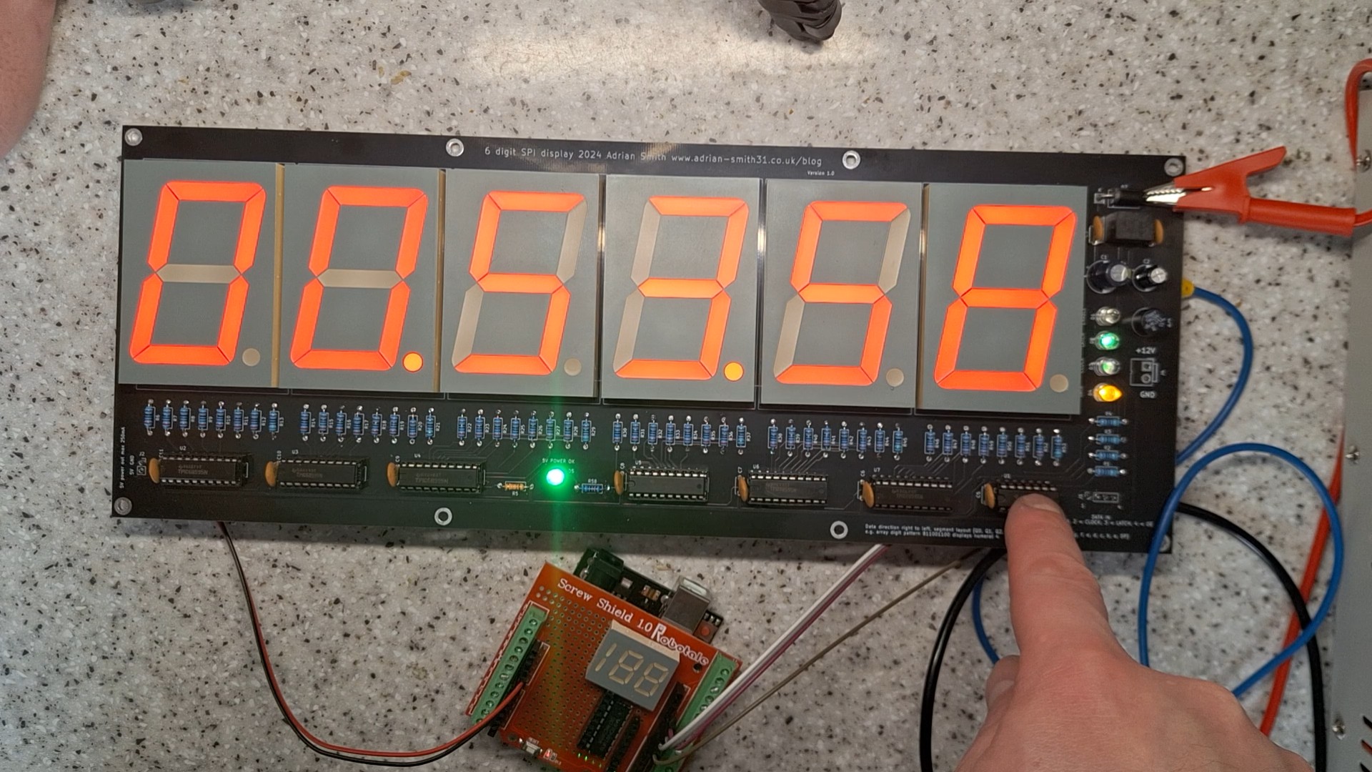
This project came to being when I wanted a large multi digit 7 segment LED display but I was only able to find MAX7219 or similar based display boards with digit heights up to 0.56″. Not being able to find what I wanted, I decided to make a 6 digit clock (one of my earlier projects) and as I had some larger 2.3″ displays spare I designed another 6 digit display this time with just the SPI interface so it can be connected to any microcontroller with a SPI interface. I also wanted to control the display brightness so this was done using the output enable pin of the shift registers connected to a PWM pin on the Arduino.
Project Description & Power Infrastructure Overview
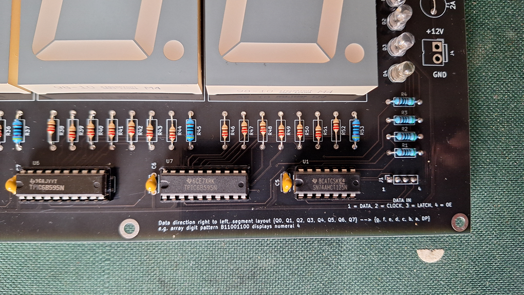
To keep costs down I decided against using external drivers with a MAX7219 and instead went with a chain of shift registers using TPIC6B595’s as their open drain outputs can sink up to 500mA (shared between all 8 outputs) and up to 50V – ideal for the large LED displays that have a forward voltage of 8.4V. The PCB would have to be powered from 12V due to the higher voltage displays so a 7805 regulator provides the 5V power for the shift registers and the input buffer which also translates 3.3V logic levels to 5V required by the shift registers.
The SPI High-Current Display Framework functions through a specialized Buffered-Shift-Sink lifecycle. The system is built on a high-reliability Power-Logic Separation model:
- Open-Drain Power Sinking: Standard ICs like the MAX7219 struggle with the 8.4V forward voltage of 2.3" displays. This project utilizes the TPIC6B595, whose specialized DMOS transistor outputs can sink up to 500mA and handle up to 50V, making it the ideal "Power Gate" for industrial LEDs.
- Logic-Level Translation Shunt: To ensure compatibility with 3.3V MCUs (ESP32/Nano 33) while maintaining 5V signal integrity for the shift registers, the system includes a 74AHCT125 Quad Buffer. This acts as a high-speed logic bridge, preventing data corruption during transmission.
- PWM Intensity Management: By connecting the Output Enable (/OE) pins of the shift register chain to an Arduino PWM pin, the project achieves hardware-level brightness control without increasing software overhead.
The board is suitable for electronics hobbyists and it provides ultra bright LED’s on the data input lines to indicate input signal status. With input signals that have a very low duty cycle the status LED’s would not light hence why ultra bright LED’s were used. Ideal for testing and development use and for use in a final, one off project. It runs off 12 volts and has an onboard regulator for the IC’s. It is compatible with 3.3V and 5V logic level inputs on the data connector.
Hardware Infrastructure & The Design Tier
- 2.3" Common-Anode Display Matrix: The "Visual HUD." These oversized displays (Kingbright SA23-11 equivalent) feature multiple LED chips per segment, necessitating the 12V power rail for clear, uniform illumination.
- LM7805 Voltage Regulator: The "Logic Guardian." It steps the 12V display supply down to a stable 5V rail for the ICs, ensuring the module is Single-Supply Compatible.
- High-Contrast Diagnostic Mesh: The PCB features ultra-bright indicator LEDs on the data input lines. This allows for real-time visual debugging of the SPI stream—if you see the lights flash, the data is flowing.
- Through-Hole Component Matrix: Specifically chosen for the "Hobbyist Developer," the PCB uses through-hole parts for ease of assembly and high-current resilience, making it a rugged choice for permanent laboratory installations.
The board was also designed with through hole components for ease of assembly and features a reverse polarity protection diode and a 5V output for powering an Arduino or similar. Current consumption with all digits and segments on is around 700mA. A 12V regulated power supply rated at 2A is needed to power this board.
Technological Logic and Execution Algorithms
The system reaches professional-grade reliability through several Firmware & PCB Strategies:
- Daisy-Chain Serial Logic: The module is designed for Infinite Expandability. Every shift register passes data to the next, meaning you can link multiple boards to create 12, 18, or 24-digit display walls using the same 3 SPI pins.
- Segment Resistor Calibration: The design specifies 270 Ohm resistors for Red displays and 220 Ohm for Green, accounting for their different forward voltage requirements and ensuring uniform 20mA current per segment.
- Reverse Polarity Interlock: The input rail features a heavy-duty diode to prevent catastrophic silicon failure in case of accidental wiring inversion—a critical feature for field-deployed deployments.
- Hardware-to-Software Decoupling: The display can be driven by a raw bit-stream. This project demonstrates how to avoid bulky libraries, using the Arduino's native
ShiftOut()command to manage the binary-to-segment mapping with 100% control.
Things to Bear in Mind if Making Your Own
Any 2.3" common anode display will suffice as long as the pinout matches the Kingbright SA23-11GWA / EWA but pay attention to the number of LED chips per segment as the current limiting resistors will need to be changed accordingly. Examples given above are for the Kingbright SA23-11EWA red displays. For example a suitable equivalent is the Liteon LTS23805HRB. There are also the cheap Chinese displays from AliExpress and eBay which often do not have a datasheet so please confirm pinout is compatible first before purchasing. The green LED displays (SA23-11GWA) have a different forward voltage so current limiting resistors should be 220 ohms for the digits and 470 ohms for the decimal points.
Improvements for future versions (or you can make if you choose to do so) is to move the shift registers to the back of the board behind the LED displays making the board narrower. Power and diagnostic LED's moved to a separate plug in board on the rear so the boards can be daisy chained.
Why This Project is Important
Mastering High-Voltage Driving and Logic-Level Shifting is an essential skill for Industrial UI Designers and Power Systems Engineers. It teaches you how to bridge the gap between "Low-Power Silicon" and "High-Visibility Output." Beyond simple clocks, these same principles are used in Production Line Status Boards, Digital Scoreboards, and Public Transit Arrival Displays. Building this project proves you can engineer a professional-grade visual asset that prioritizes power efficiency, signal integrity, and high-visibility performance.
Technical Note: A 12V 2A regulated power supply is required to drive all 6 digits at maximum brightness (approx. 700mA peak draw).