Story
Our love for music was not enough for us to learn playing instruments except for a few basics of guitar and saxophone. The background in physics we had pushed us to delve into incorporating technology and music together. We thought of the possibility of enhancing the guitar, the most famous instrument of all time. It could outperform the classical guitar with its metal string by creating more flexible options for the player and his/her performance. The project aims to design and build a guitar based on an optical setup built of Lasers, Beam Splitters, and Light sensors. The strings of the guitar will be replaced by an optical setup. The general technique for playing guitar to shorten the string by pressing your hand on the desired fret, and plucking with your other hand the string needed to produce the note or chord you want. If no fret is compressed, it is called an open string. Note that many techniques were invented during the years: Pulling, tapping, sliding, etc… however, we will stick to the standard way of guitar playing.
Concept
The design is composed of two modules, mimicking the two main tasks of playing guitar. By receiving certain information, The microcontroller would generate the desired note.

The first module (P-Module) resembles the plucking hand. When the right-hand plays on a guitar string, the string will vibrate, and create audible tones with different amplitudes.The laser guitar is able to determine if a laser is plucked, breaking the beam, the signal will be sent.
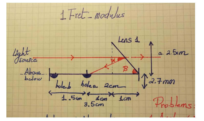
The second module (F-Module) is the fretting hand. While the guitarist is striking a note, he will hold the string at a unique fret. The system will be able to localize where the fretboard is touched so that when the laser is also plucked, the desired note will be produced.
Technical Deep-Dive
This project, "Laser-Synth," is a sophisticated exploration into Musical Physics and Opto-Electronic Synthesis. By replacing traditional metal strings with precise laser beams, it digitizes the haptic experience of playing a guitar. The core of the system is a custom optical setup that creates a 3-string, 2-fret matrix where beam interruption triggers real-time MIDI (Musical Instrument Digital Interface) packets.
Beam-Splitter Physics & Refraction Forensics
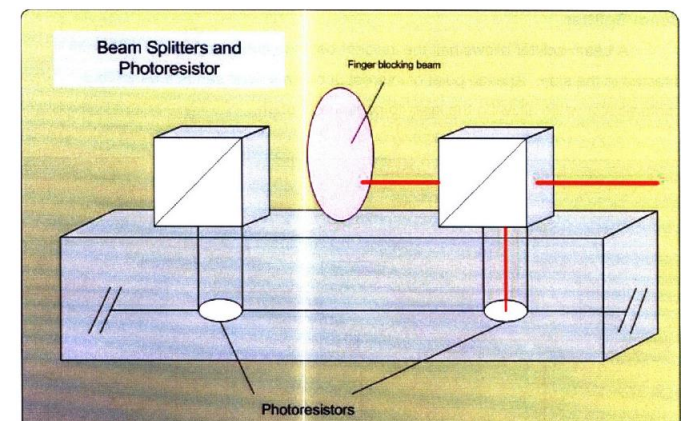
- The Snell’s Law Bridge: To avoid the high cost of industrial beam splitters, the system utilizes microscope slides. This triggers Partial Internal Reflection, where a portion of the beam is reflected to a "Fret" sensor (F-Module), while the remainder passes through to the "Pluck" sensor (P-Module).
- Reflectivity Analysis: Using Fresnel equations, the system calculates the reflectivity ($R$) of the glass interface. Thermal and optical losses are documented at approximately 1.4dB per slide, ensuring sufficient intensity remains for the final LDR node in the chain.
MIDI-over-Serial Protocol Forensics
- The 3-Byte Packet: The Arduino doesn't send "Sound," it sends "Instructions." Each pluck generates a standard 3-byte MIDI message:
- Status Byte: (e.g., 0x90 for Note On / 0x80 for Note Off)
- Data Byte 1: The Note Number (e.g., 60 for Middle C).
- Data Byte 2: Velocity (0-127, simulating pluck intensity).
- Latency Mitigation: To solve playback delay, Laser-Synth utilizes the Hairless MIDI Bridge. This converts raw serial data into a Virtual MIDI Port, achieving near-zero latency for professional performance.
LDR Threshold Diagnostics
- ADC Resolution Mapping: The LDRs are paired with 10k resistors in a voltage divider mesh. The Arduino's 10-bit ADC monitors for sudden voltage shifts ($V_{out}$) caused by beam occlusion. The software implements a dynamic threshold to compensate for ambient light pollution.
Setup
The Beamsplitters are very expensive (ranges from 200$ per piece) and also not easy to find. Therefore, we decided instead to use optical microscope slides. After experimenting with the lenses, we found that at an angle around 40-50 degrees the slide was reflecting partially the light back with 30 degrees downward and at the same time the light was partially passing to the next slide with some adjustment.
Choosing the right angle of the lens
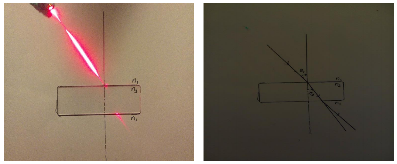
When light enters with a higher index, the refractive angle will be smaller than the incidence angle and it will shift closer to the normal. According to Snell’s law,
𝑛1 sin 𝜃1 = 𝑛2 sin 𝜃2
First, we fixed the lens on the paper and drew a normal line to the surface. Using a laser, emitted light through the lens. Secondly, we pointed the line of the refracted light by joining the incident light, with the angle in respect to the normal denoted by 𝜃1, with the line coming out of the lens which is parallel. The angle of the refracted line is denoted by 𝜃2. Third, we repeated the experiment four times in order to get the correct measurements.
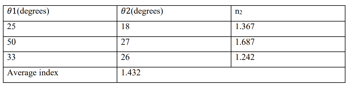
we repeated the experiment a few times and the results are shown in the table below
Then we had to calculate the reflectivity of the lens used
In order to calculate the reflectivity, we can use Fresnel equation to calculate which reduces for formal incidence to this form:
𝑅 = |(𝑛1−𝑛2)/(𝑛1+𝑛2)|^2
Then R = ((1-1.432)/ (1+1.432)) ^2= 3.155%
Then, the light reflected by the lens will be 3.155% compared to the theoretical value which is 4%.
Sensors
Light Intensity Loss After Passing through slitsAn experiment was set up to calculate the loss in laser light power/intensity as it passed through the microscope slides. The results were used for determining the feasibility of slides for our project. Following components were used in the experiment:
- Laser light emitter 650nm (rated power 5mW).
- LDR D5717 sensor with a spectrum peak value of 540nm.
- Arduino built-in 10bit ADC
- 10K resistor
- Microscope slides
The lDR and laser light were chosen so that the emission wavelength of the laser was close to the peak spectrum value of LDR. In addition, 650nm laser was easily available and much cheaper than green 500nm laser emitter.

Now let’s calculate the power loss in decibels.Here we will take Vin as voltage when there was no slit between laser and sensor.
Hence V_in=4.1V.
P_loss = 20.log(V_o/V_in)
The above results suggest a very little power loss in laser light as it passes through the slides.The loss is partly due to the reflected light. In addition, some light is dispersed in the slides.Hence, a maximum loss of 1.4dB is acceptable for our application. In addition, the LDR’s can be adjusted for variable light values by using a potentiometer built in each digital LDR being used for the project.
Engineering & Implementation
- Hierarchical Logic Modules:
- P-Module (Plucking): Detects the "Attack" of the note. Breaking this beam triggers the `Note On` command.
- F-Module (Fretting): Determines the "Pitch" offset. The logic checks the status of the fretboard beams concurrently to calculate the target MIDI note before the pluck signal is sent.
- Opto-Mechanical Calibration: Precise axial alignment is critical. The lasers are fixed on a rigid rail, while the microscope slides are mounted on pivoting nodes for fine-tuned refractive indexing. 650nm (Red) lasers are utilized for their alignment visibility and low cost.
Music
After conducting thorough research on music, and especially on the notes of the guitar. At first, we found a library, in MP3 form, for an acoustic guitar with 14 frets. However, after trying this on our setup, we faced a problem, which is response time. By Response time in here, I mean the time it took to generate the sound after the light was cut, approximately 0.5s, which is slower than actual playing.
Secondly, we could find a well-known program called Midi. MIDI1, Musical Instrument DigitalInterface, is an industry-standard music technology protocol that connects products from many different companies including digital musical instruments, computers, tablets, and smartphones. MIDI is used every day around the world by musicians, DJs, producers, educators, artists, and hobbyists to create, perform, learn, and share music and artistic works. In our work, we found the corresponding conversion table as well here. In the third place, in order to generate the desired instrument, we tried many programs like Jim Oliver. Unfortunately, they were not open source. Lately, we decided to use garage band and integrated with hairless MIDI and Arduino as explained later in the programming part.
Hardware
Although the real circuit is complex because of a large number of sensors. A simple sketch of the circuit is included below both as schematics and its look on a breadboard. The design here consists of LDRs, laser, Arduino, and USB connection for MIDI interfacing. The design shows that Arduino is not only collecting data from the sensors but also sending it to the MIDI system for producing sound.
Software
The programming was developed in Arduino studio environment. The Sketch uses MIDI Arduino library; and it is our final version of the codes used to run the Guitar. Arduino, send a Serial message that contains 3 information.1- The Note number, each musical note has a MIDI number.2- The velocity, how intense the sound should come out(volume).3-Channel for further more music editing. Please note that velocity and channel in this code are considered to be fixed, meaning that all notes are played with equal volumes.Important comments are made in red and bold to explain the following code in the software part.
After running this sketch the Arduino is able to tell which note to play and when to launch the MIDI message to the computer. Mac OS has java MIDI library built into its system while forWindows and Linux users, MIDI Loop2is an essential software to use so that the computer can recognize the message. Then there two possible software: Hairless MIDI3, and Serial-MIDIconverter4. They read this Serial message and convert it to MIDI message. Finally, this MIDImessage is recognized by Virtual MIDI software, for this project we used GarageBand5, available for free on Apple store.
This way we could get The serial message from Arduino and play the requested note. Thus, we do not need a midi cable or connections of that sort. The serial message transmitted via a USB cable can mimic the MIDI message and give accurate results. However, using a midi cable gives a better result especially for instruments like an acoustic guitar.
This way we could get The serial message from Arduino and play the requested note. Thus, we do not need a midi cable or connections of that sort. The serial message transmitted via a USB cable can mimic the MIDI message and give accurate results. However, using a midi cable gives a better result especially for instruments like an acoustic guitar.
Results
We could at last build a guitar with 3 strings and 2 frets and sticking to the budget.
Here is a video of our guitarist friend playing some tunes
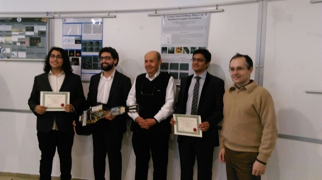
and few pictures for us receiving the award for the best project of the semester
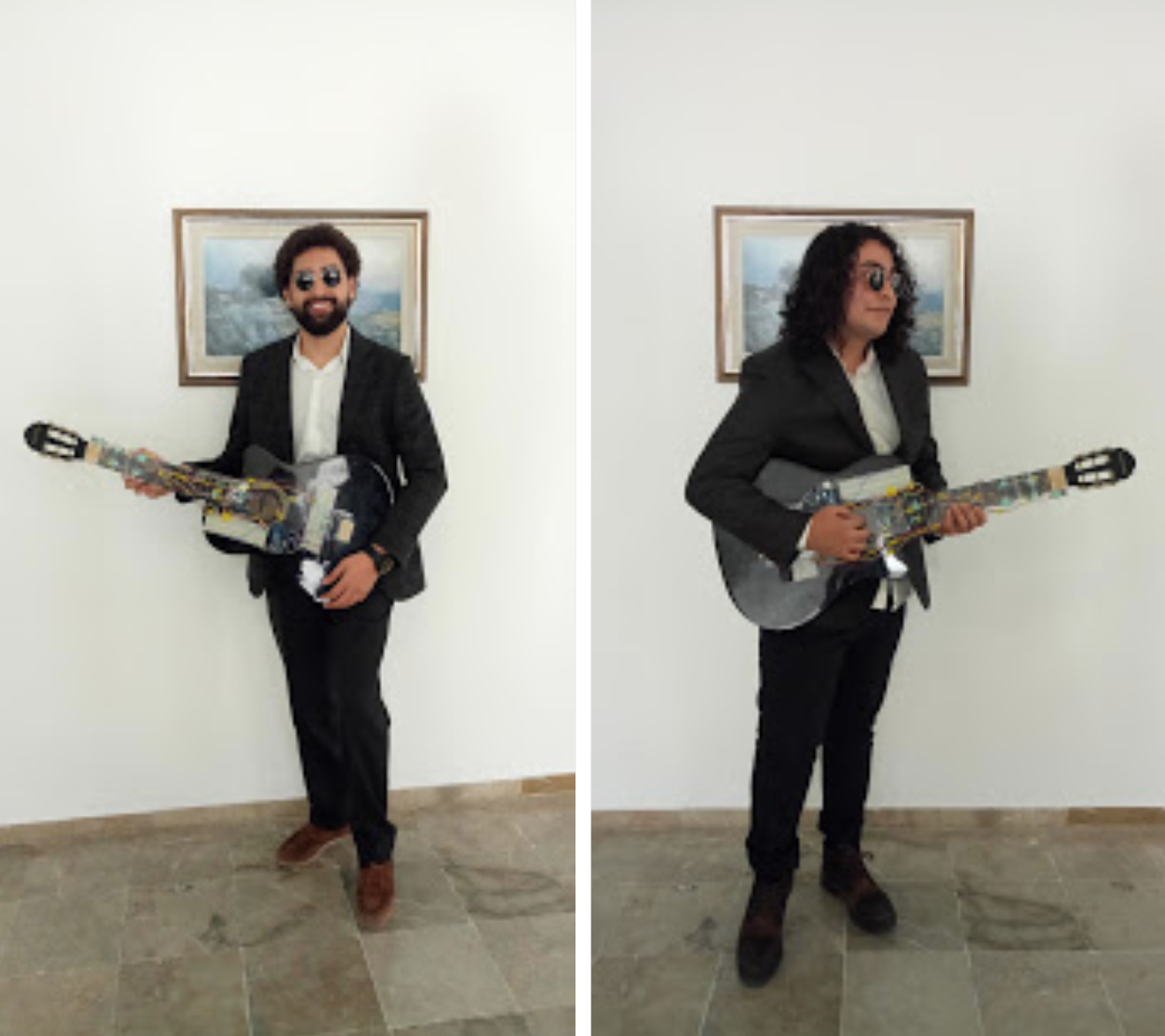
and cooler pictures going solo
Conclusion
Laser-Synth bridges the gap between Optical Physics and Digital Music Production. By mastering Snell's Law Forensics and MIDI Packet Construction, developers can create avant-garde instruments that push the boundaries of traditional performance art through embedded technology.
Optical Harmony: Mastering the fretboard through refractive forensics.
References
Useful Links
http://www.instructables.com/id/Arduino-Xylophone/?ALLSTEPS
http://www.instructables.com/id/Laser-Guitar-2/?ALLSTEPS
http://www.instructables.com/id/The-Prism-A-Laser-Synth-Guitar/?ALLSTEPS