*******
Please visit https://proteshea.com/led-and-switch-array/ for a complete list of materials needed for this project.
*******
Project Overview
The "High-Density I/O Interface" project is a rigorous technical exercise in maximizing the available resources of the Arduino Uno Rev3. By interfacing a 10-segment LED bar graph and an 8-position switch array, the project utilizes 14 of the Uno's 14 primary digital pins. This project demonstrates foundational engineering principles: current-limiting for LED protection, pull-down resistor logic for stable inputs, and the use of Bussed Resistor Networks (SIP) to maintain a compact and professional breadboard layout. It is an essential lesson for developers transitioning from simple single-LED circuits to multi-component system design.
Introduction
If you haven’t read our Getting Started Guide for the Arduino Uno Rev3, please read that first. Otherwise, continue reading. In this tutorial, we’ll be maxing out the digital I/O on the Arduino Uno Rev3 (Uno). We interface a 10-segment LED bar graph and an 8-segment switch array. We’ll use 9/10 LEDs on the bar graph and 5/8 switches on the switch array for a total of 14 pins that we’ll need on the Uno. Each LED input will be an output from the Uno and each switch output will be an input to the Uno.
LED Bar Graph
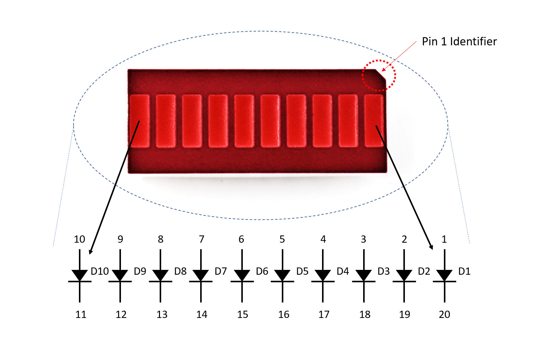
The LED bar graph consists of a vector of independent LEDs. The number and color of the LEDs can vary, but we’ll be using a red, 10-segment bar graph. The internal circuit and pin assignments are shown in the image below. Each LED is oriented the same internally, so the anodes are pins 1-10 and the cathodes are pins 11-20.
To limit the current passing through each LED, we’ll be using a 470 ohm, 9-resistor array. If you do not place a resistor in series with the LED, you are essentially shorting power to ground and could damage the LED or power supply.
There are two important numbers to look for in the LED’s datasheet. The first one is the forward voltage which is the voltage drop across the LED. This is usually given as a maximum rating, so you want to make sure to keep the voltage at or below the forward operating voltage. The second is the forward current which is the maximum current that should be sourced to the LED. For example, the forward voltage and current for each LED in the bar graph is 2.6V and 25mA, respectively. The circuit for one LED is shown below.
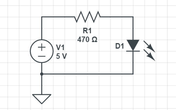
LED Forward Bias Calculation: Each segment in the bar graph has a Forward Voltage ($V_f$) of approx 2.6V and a max current of 25mA. By using a 470 Ohm resistor at 5V, the system limits the current to: $I = (V_{source} - V_f) / R = (5V - 2.6V) / 470\Omega \approx 5.1\text{mA}$. This ensures high visibility while operating well within the safe thermal limits of both the LED and the ATMega328P microcontroller pins.
The 470 ohm resistor is a little big when connecting to a 5V source. The current through the LED will be around 5mA, but the LED is still bright enough. We did this because the FuelCan does provide +12V, so if you wanted to use that rail for the LEDs, you’d still be under the forward current rating.
Switch Array
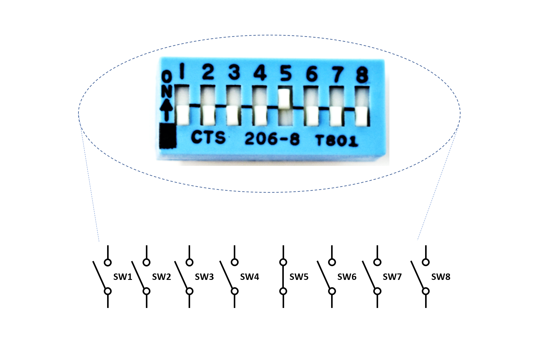
The switch array varies in the number of switches and type – we’ll be using an 8-position SPST (single-pull double-throw) slide switch. A schematic of the switch array is shown below. Notice that when the switch is in the OFF position, the switch is open. When the switch is in the ON position, such as switch 5, the switch is closed. Similar to the LED, we also want to limit the current passing through the switch to prevent damage and minimize power consumption.
When you’re consulting the documentation for the switch, you want to look for the max voltage and current. For example, the max voltage and current for this switch array is 24V and 50mA, respectively. We’ll be using a 1.2k ohm resistor in series with each switch array, and the +5V supply on the FuelCan. This means that the current passing through the switch will be ~4.2mA (I = V/R = 5/1.2k). The circuit schematic is shown in the image below.
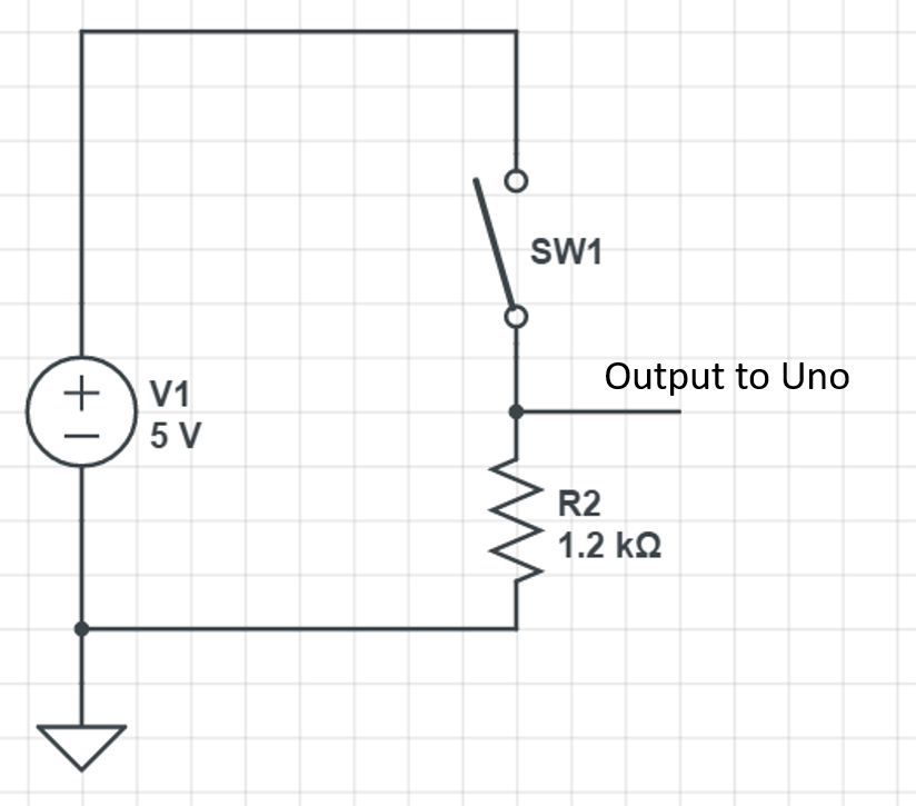
Switch Array Input Logic: The 8-position SPST switch array is configured with External Pull-Down Resistors (1.2k Ohm). When a switch is open, the Arduino pin is tethered to Ground, ensuring a stable "LOW" reading. When closed, it connects to +5V, sourcing approx 4.2mA of current. This prevents the "Floating Pin" effect that leads to erratic logic errors in digital circuits.
Let’s say we chose a smaller resistor value, 680 ohms. The current through the switch would be ~7.4mA (I = 5/680), still under the max current rating of the switch. But, we would have a higher power consumption. Power is equivalent to the voltage multiplied by the current (P = V x I), so the power consumption for using the 1.2k ohm and 680 ohm resistor would be 20.8mW and 36.7mW, respectively. This may not seem like a big difference, but when you are designing low-power applications, this difference is huge.
Engineering & Low-Power Design
- Power Consumption Trade-offs: The project highlights the importance of choosing resistor values based on the application's power budget. Moving from a 680 Ohm to a 1.2k Ohm resistor for the switches reduces power consumption per switch from 36.7mW to 20.8mW. While negligible for a desktop project, this 43% reduction is critical for battery-powered or mobile embedded systems.
- Circuit Protection: The documentation emphasizes that missing a series resistor effectively creates a "Hard Short" from VCC to Ground through the LED's semiconductor junction, which can lead to catastrophic failure of the Arduino's output driver stage.
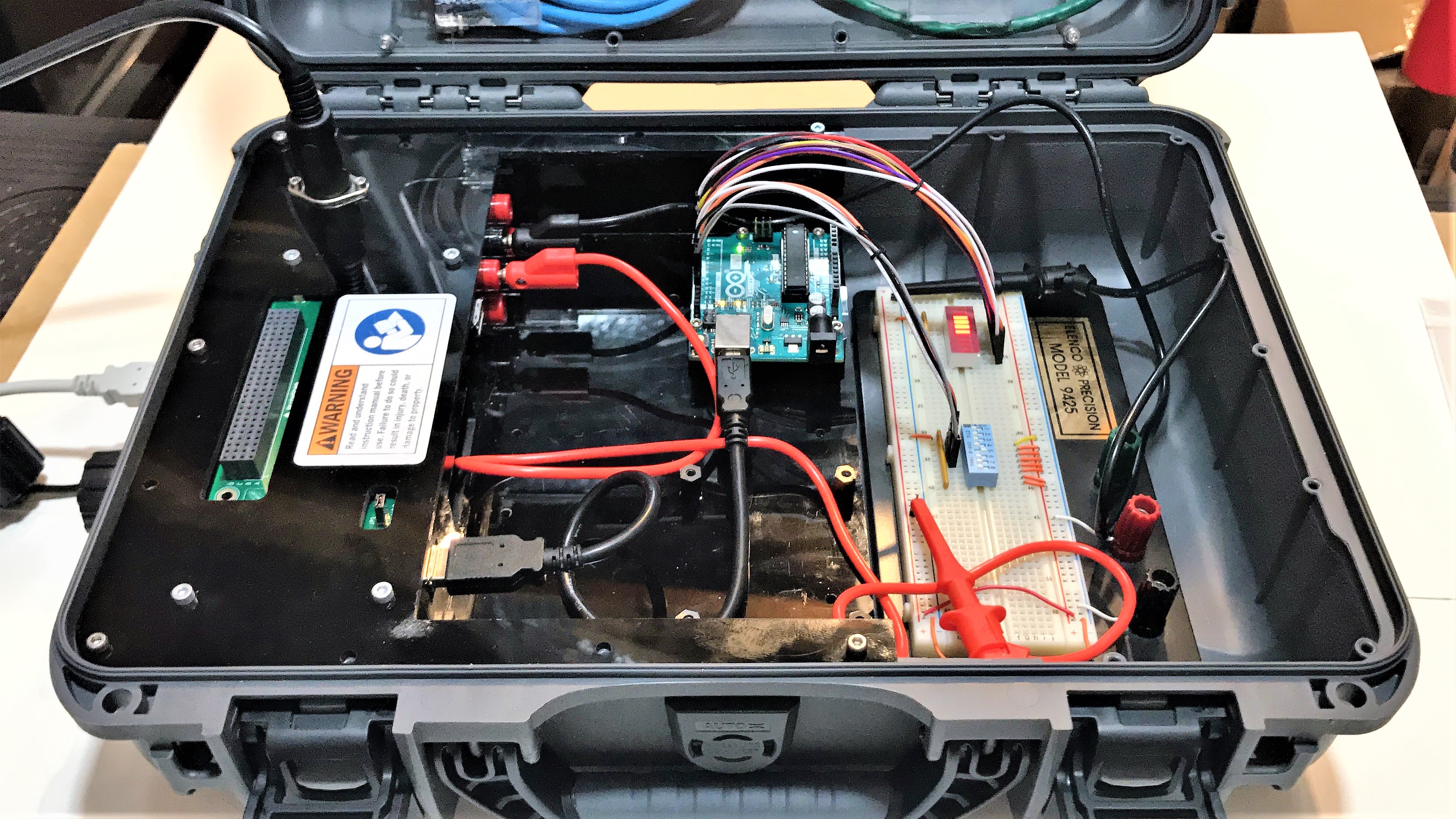
- Prototyping Precision: Using a "FuelCan" or similar prototyping workstation allows for stable 5V/12V rails and organized cable management, transitioning the user from "spaghetti wiring" to a more industrial prototyping mindset.
Resistor Array
The resistor array is made up of a number of bussed (one lead of each resistor shares a common node with the other resistors in the array) resistors, in this case, 9 resistors. These are beneficial for adding a series resistor to multiple, identical components such as the LED bar graph or the switch array. They also help with keeping your wiring clean and compact. The internal circuitry of the 1.2k ohm resistor array is shown in the image below (the 470 ohm array has a similar internal circuitry). When you look at the resistor array, pin 1 is identifiable with the dot. This can be connected to power or ground, but make sure to consult the datasheet for the max voltage rating if you are connecting it to power.
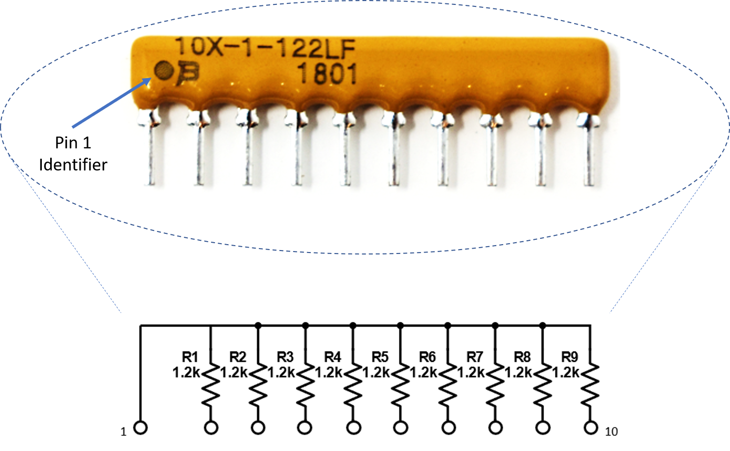
SIP Resistor Network Architecture: To save space and simplify wiring, this project employs Single In-line Package (SIP) resistor arrays. A "Bussed" resistor array (identified by the dot on Pin 1) connects one side of every internal resistor to a common node. In this circuit, Pin 1 is tied to Ground, providing an efficient path for the 9 LED cathodes or switch pull-downs without requiring individual jumpers for every component.
Wiring
I’m using a breadboard instead of Modulus since almost everybody has a breadboard. First, let’s place the LED bar graph and switch array onto the breadboard. Insert both so that the body is over the valley of the breadboard. You do not want the pins to short each other by being connected to the same node. Next, place the 470 ohm resistor array on the cathode side of the LED and tie pin 1 of the array to GND. Make sure that pin 1 of the resistor array is not connected to any of the cathodes of the LED bar graph. Since the bar graph has 10 LEDs and the resistor array only has 9 resistors, we can only use 9 out of 10 LEDs.
Next, use a M/M jumper to wire the anode side of the LED bar graph as outputs to the Uno pins 0-8. For example, pin 10 of the bar graph will get wired to Uno pin 0, pin 9 of the LED will get wired to Uno pin 1, and so on.
I/O Resource Management: On the Arduino Uno, Pins 0 and 1 are shared with the Hardware Serial (USB) bridge. This project demonstrates that these pins can be used as GPIO (General Purpose Input/Output) as long as the developer is aware that they must often be disconnected during the code upload process to prevent signaling conflicts.
Place the 1.2k ohm resistor array as shown in the image below. Tie pin 1 of the array to GND, and make sure it does not connect to any of the switch pins on the switch array. The breadboard holes outlined in yellow will be tied to Uno pins 9-14. For example, switch 1 will be wired to pin 9, switch 2 will get wired to pin 10, and so on. Tie the other switch pins, 1-5, to +5V.

If you haven’t mounted the Uno onto the prototyping area of the FuelCan, go ahead and do that. I placed the breadboard in the bottom storage compartment to limit the length of the jumper wires. We need to supply +5V and GND to the power and ground rails on the breadboard. Use the provided banana jack to test-lead clip cables to do so. You will need two male header pins to mount the test-lead clips to on the breadboard side. Plug the Type A side of the USB cable into USB1 receptacle and the Type B side into the Uno’s receptacle. Power up the FuelCan with the AC-DC power adapter.
Software
Once the wiring is complete and the FuelCan is powered up, we can now load the sketch onto the Uno. To change the LED function, simply change switches 1-5 to the ON position. If there are multiple switches in the ON position, the LED function will take priority based on the lowest switch number. For example, if switches 1 and 3 are ON, the LED function will be the one mapped to switch 1.
Software Priority Logic: The provided sketch implements a priority-based state machine. If multiple switches are active, the software resolves the conflict by favoring the lowest index (e.g., Switch 1 takes precedence over Switch 3), a common logic pattern in PLC and industrial control systems.
Complete Setup