This is my first project using Arduino UNO. Using the code given we can change the intensity of an LED automatically.
This code increments and decrements the intensity of an LED in 255 steps with a selective delay. This code uses analogWrite(PWM) in 8-bit mode. That means intensity can be controlled in 255 steps. I tried different code logic for this project.
Technical Implementation: Pulse Width Modulation and Duty Cycles
The project reveals the hidden layers of a simple sensing-to-glow interaction. The core mechanism is Pulse Width Modulation (PWM), a technique where a digital signal is switched on and off very quickly to simulate an analog voltage. The percentage of time the signal is "on" (HIGH) versus "off" (LOW) is called the duty cycle. By varying this duty cycle from 0% to 100%, the Arduino can control the average power delivered to the LED, making it appear to fade smoothly.
- Identification layer: The Arduino's internal timer acts as a high-resolution chronological engine, generating the precise square wave for the PWM signal.
- Conversion layer: The system uses the 8-bit PWM resolution to map 256 discrete steps (0-255) to corresponding duty cycles, allowing for fine-grained brightness control.
- Visual Interface layer: A High-Brightness LED provides clear visual feedback for each brightness step.
- Communication Gateway layer: A Standard Arduino Pin (PWM-capable), such as Pin 10 in this project, provides the physical output for the signal.
- Processing Logic: The Arduino code follows a "duty-cycle-dispatch" strategy: it interprets
analogWrite()instructions to set the PWM duty cycle, creating a rhythmic pulsing illumination.
Hardware-Software Infrastructure
- Arduino Uno: The microcontroller board that executes the code and generates the PWM signal.
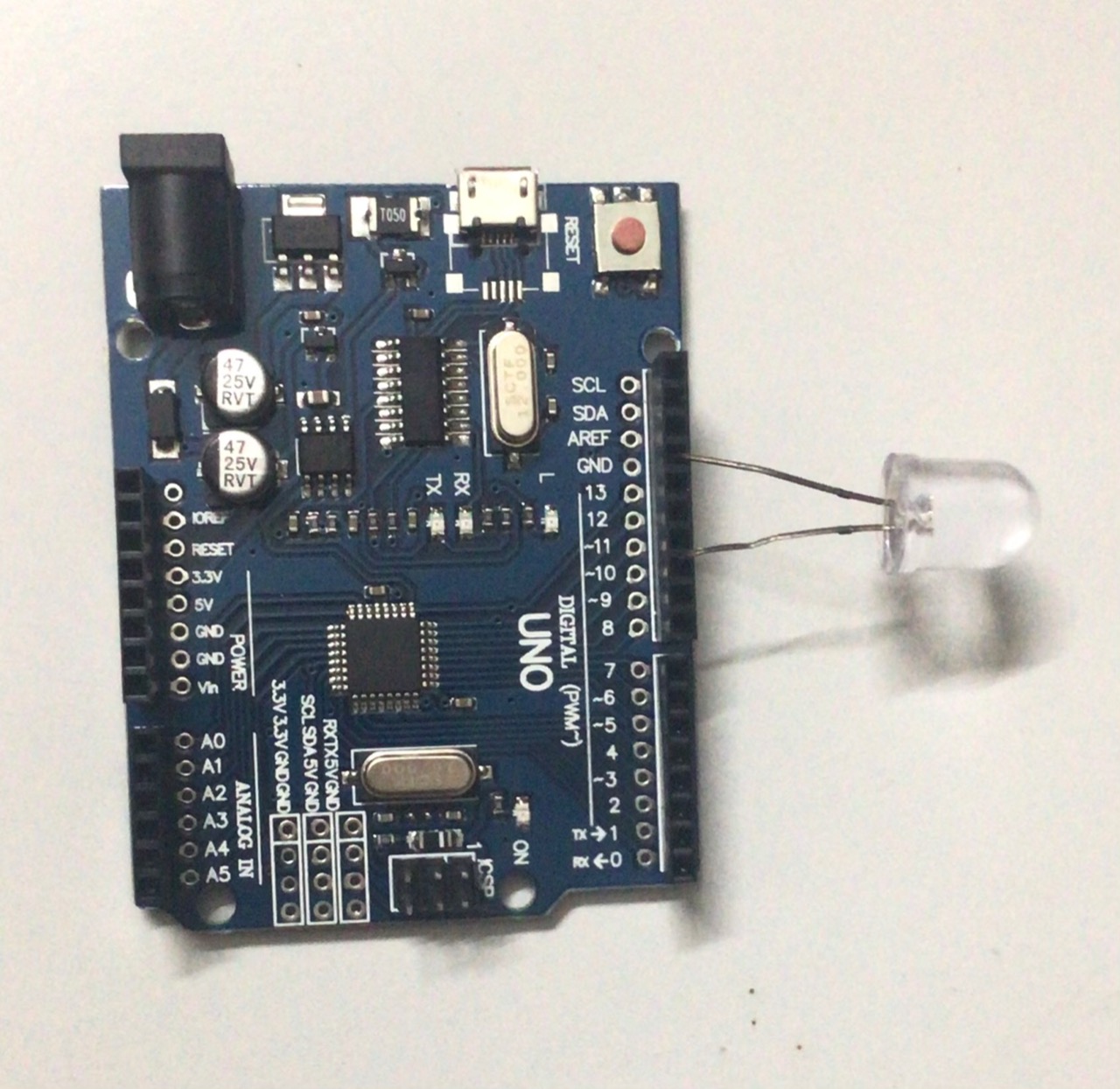
- LED Output: A 10mm LED is connected to pin number 10 on the Arduino UNO board, providing the visual output.
- PWM Pin (Pin 10): The digital pin capable of outputting the PWM signal to control the LED brightness.
- Breadboard: Used for creating a temporary, solderless prototype circuit.
- Resistor (220 Ohm): This current-limiting resistor is essential to protect the LED from excessive current, preventing burnout. It should be connected in series with the LED.
- Micro-USB Cable: Used to upload the code to the Arduino and provide power.
First version of the code
There are 2 while loops in this version. Initially, the intensity is high. Hence, the first while loop is used to decrement intensity from 255 to 0 with a delay of 5 milliseconds.
 while(intensity != 0)
 {
   analogWrite(10, intensity);
   delay(d);
   intensity = intensity - 1;
 }
This while loop ends when intensity becomes 0 and the second while loop starts. In this loop, intensity increments from 0 to 255.
 while((intensity < 255) && (intensity >= 0))
 {
   analogWrite(10, intensity);
   delay(d);
   intensity = intensity + 1;
 }
int intensity = 255;
int d = 5;
// the setup function runs once when you press reset or power the board
void setup() {
 // initialize digital pin 10 as an output.
 pinMode(10, OUTPUT);
}
// the loop function runs over and over again forever
void loop() {
 while(intensity != 0) //this loop is to decrement intensity
 {
   analogWrite(10, intensity);
   delay(d);
   intensity = intensity - 1;
 }
 while((intensity < 255) && (intensity >= 0)) //increment intensity
 {
   analogWrite(10, intensity);
   delay(d);
   intensity = intensity + 1;
 }
}
Second version of the code
Two variables intensity and flag are used in this version. When the flag is 0, intensity increments. When intensity becomes high, i.e., 255, the flag becomes 1. When the flag is 1, intensity decrements and so on.
int intensity = 0;
int flag = 0;
int d = 5;
void setup() {
 pinMode(10, OUTPUT);
}
void loop() {
 analogWrite(10, intensity);
 delay(d);
 if(flag == 0)
   intensity = intensity + 1;
 if(intensity == 255)
   flag = 1;
 if(flag == 1)
   intensity = intensity - 1;
 if(intensity == 0)
   flag = 0;
}
These 2 versions are a bit lengthy so I tried to make it short. The 3rd version is the outcome.
Third version of the code
I used abs() and intensity++ in this version. Intensity starts increasing from -255 to 255 then goes back to -255 and the loop continues. The abs() function returns the absolute value, so abs(-255) is 255, abs(0) is 0, etc.
int intensity = 255;
int d = 5;
void setup() {
 pinMode(10, OUTPUT);
}
void loop() {
   analogWrite(10,abs(intensity));
   delay(d);
   if(intensity++ == 256)
     intensity = -255;
}
Final version of the code
This is the shortest code so far after all the trial and errors. It uses a variable intensitychange to control the direction of the fade. When intensity hits 0 or 255, the sign of intensitychange is reversed, causing the fade direction to flip.
int intensity = 255;
int intensitychange = -1;
int d = 5;
void setup() {
 pinMode(10, OUTPUT);
}
void loop() {
 analogWrite(10, intensity);
 delay(d);
 intensity = intensity + intensitychange;
 if((intensity == 0) || (intensity == 255))
 {
   intensitychange = -intensitychange;
 }
}
Interaction Hub Automation and Interaction Step-by-Step
The fading process is designed to be very user-friendly:
- Initialize Workspace: Correctly seat your LED and 220-ohm resistor in series on your breadboard. Connect the resistor to Arduino Pin 10 and the LED to GND.
- Setup High-Speed Sync: In the Arduino IDE, copy one of the code versions above. The
setup()function initializes Pin 10 as an output. - Internal Dialogue Loop: After uploading, the
loop()function runs continuously, performing the brightness calculations and updating the PWM signal in real-time. - Visual Feedback: Watch your LED automatically fade up and down, creating a rhythmic pulsing light.
Future Expansion
- OLED Identity Dashboard Integration: Add a small OLED display to show "Duty Cycle (%)" or other metrics.
- Multi-sensor Sync: Connect a potentiometer to manually control the fade speed or maximum brightness using
analogRead(). - Cloud Interface: Add a WiFi module to control the LED fade pattern remotely via a web dashboard.
- Advanced Customization: Modify the code to use non-linear fade patterns (e.g., logarithmic) for more natural-looking brightness changes.
[!IMPORTANT] The LED requires a current-limiting resistor (e.g., 220 ohms) in series to avoid LED burnout. Always double-check your circuit connections before powering it on.