This is our first project with Arduino for the Digital Systems course in Computer Science graduation from Cesar School (Recife, Brazil).
Our final goal is to create a prototype of an Art Installation, a videowall made of a matrix of LED lights, creating an interactive panel of pixelated images that interacts with the public.
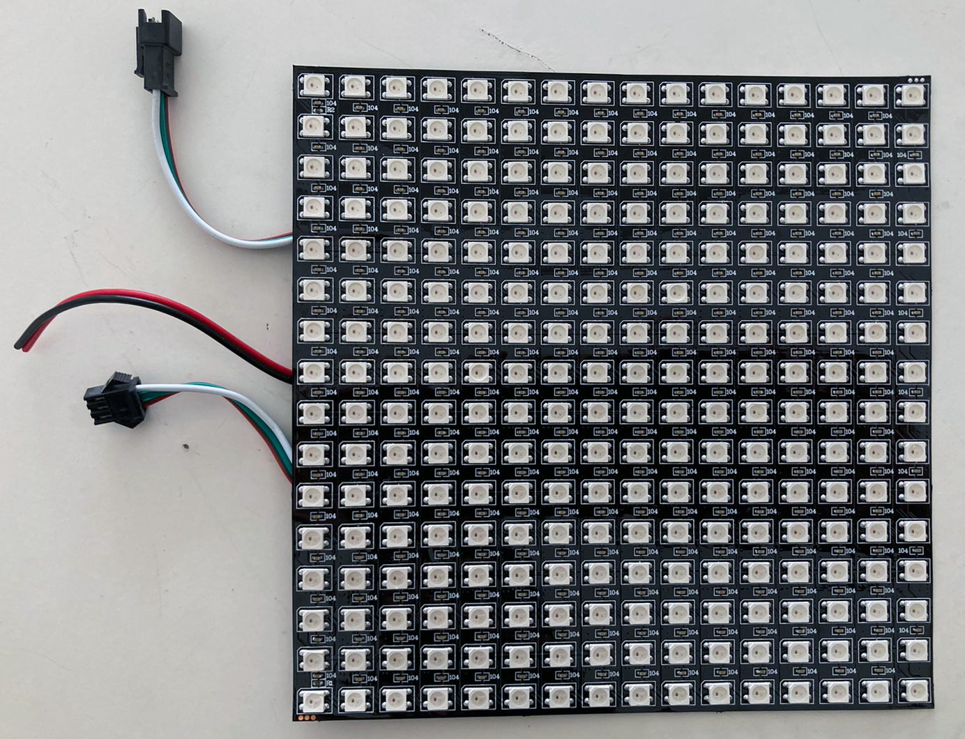
To achieve this goal, this is our first small step in the project: create a smaller version (32x16cm) led panel that randomly lights colorful pixels when the public walks in front of it, or interacts with the ultrasonic sensor.
1. Power Supply Setup
The 16x16 led matrix has 256 dots, since it is RGB, it has 768 leds with the typical 20mA each. So, all leds on max brightness will require 15.36A for just one matrix. Later, we concluded that we wouldn´t require even 50% of that power, and that it was easily manageable in code. Still, BE CAUTIOUS of the power supply that your project will require when dealing with led matrices and strips.
Leds usually works with 5V, same as the Arduino board.
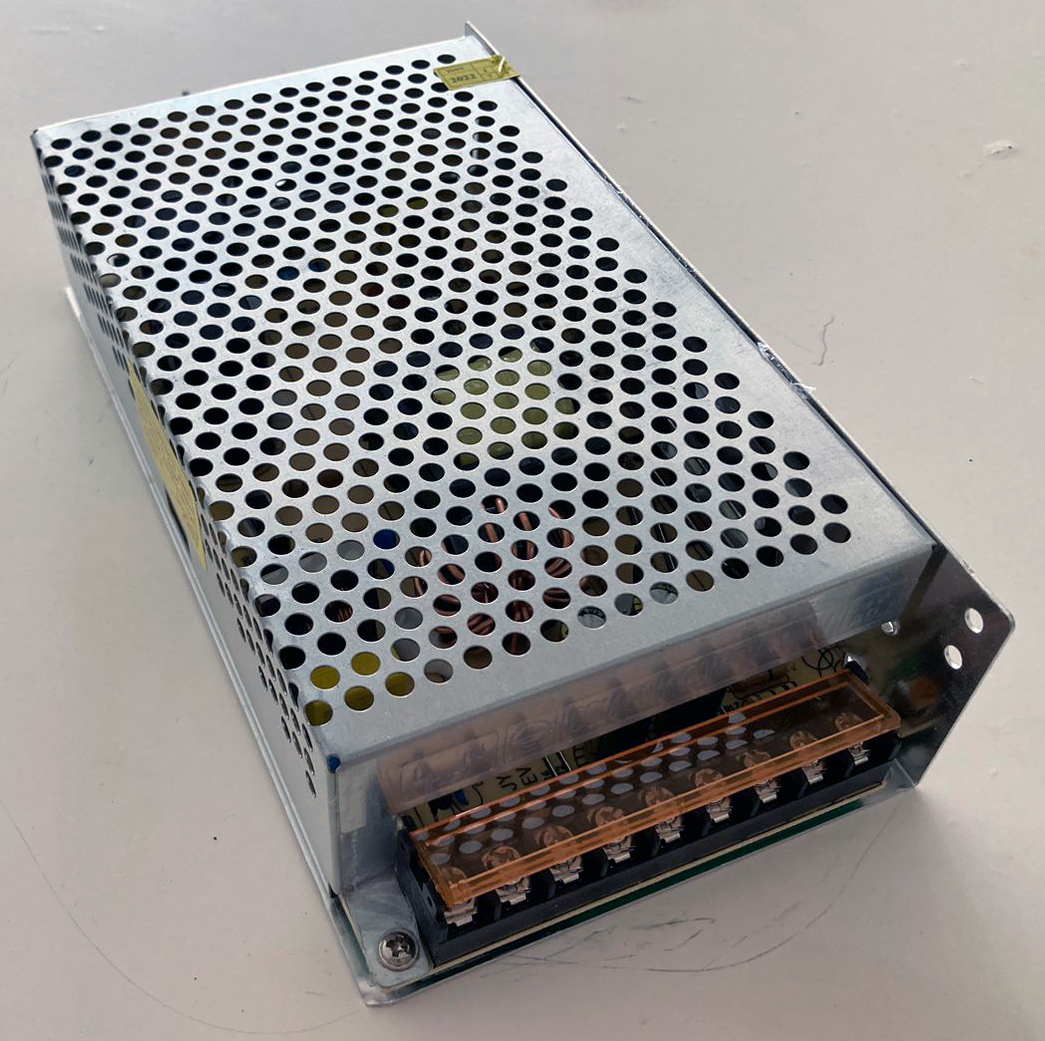
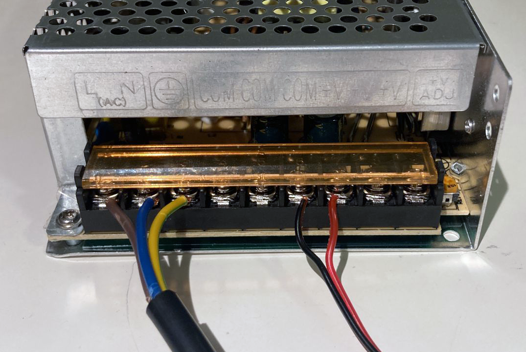
First, the Arduino board won´t supply enough power for the leds, so you will need an external supply:
Then, connect the terminals:
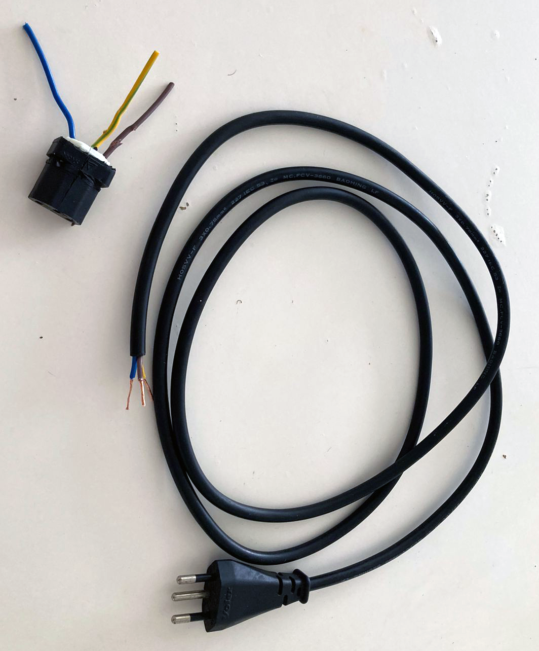
Connect line, neutral and ground wires in the correct terminals:
(search about the wiring color codes, and double-check the indication signs)
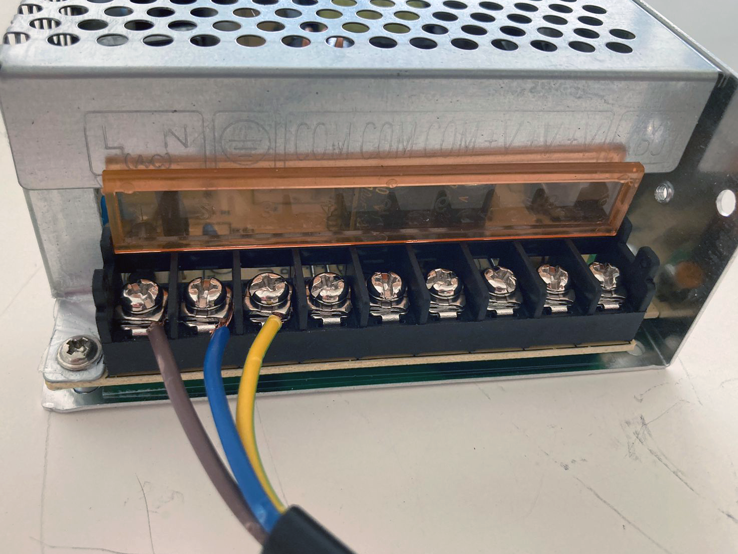
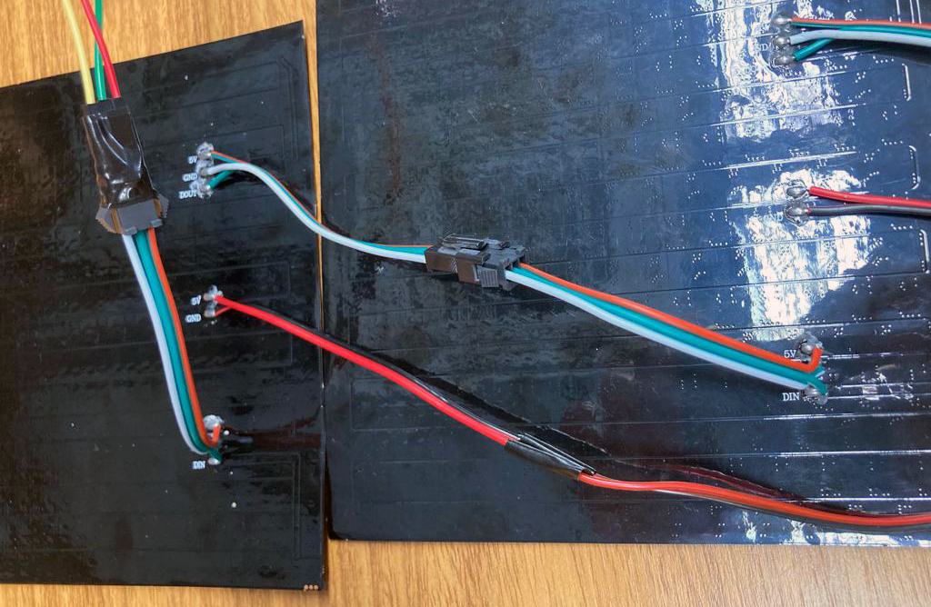
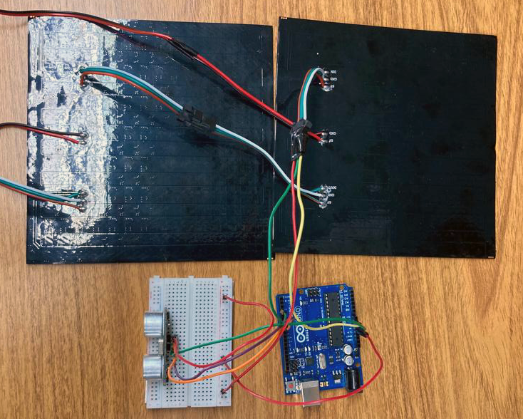
Now, we need to power the LED matrix, as you can see on the photos below, we connected the 5V and a GND, in the middle, to the respective terminals of the power supply:
2. LED Panels Setup
Connect:
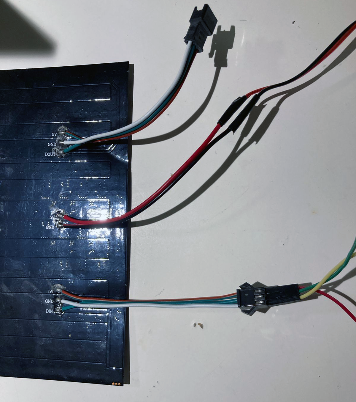
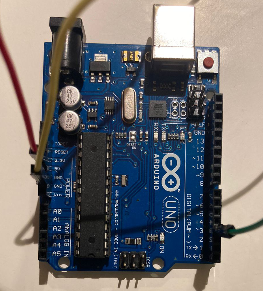
- The LED Panel's data in (DIN--to--3) Arduino´s.
- The LED Panel's ground (GND--to--GND) Arduino´s.
- The LED Panel's power line (5v--to--5v) Arduino´s.
You can power the Arduino board and peripherals with the same power supply using the extra 5V terminals that the led panel provides, or just connect the GND and power the board through the USB or another power supply.
** Also you can use the breadboard to better organize the power as you´ll see later below.
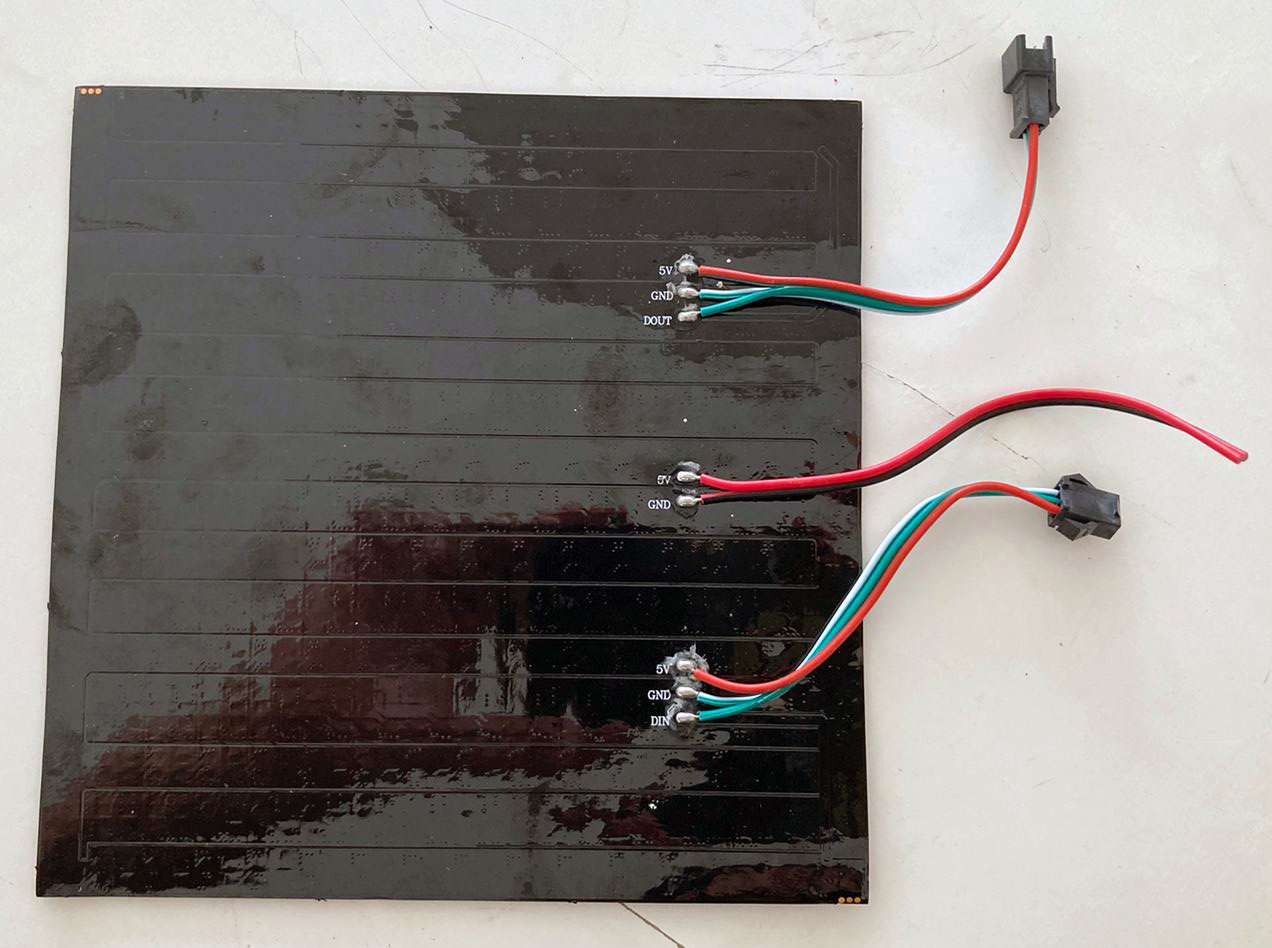
From here, we could start testing our code to control the LED panel, but first we are going to add a second LED panel:
Just connect the output terminal from one panel to the input of the other:
3. Ultrasonic Sensor Setup
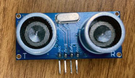
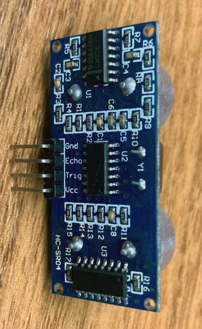
Connect:
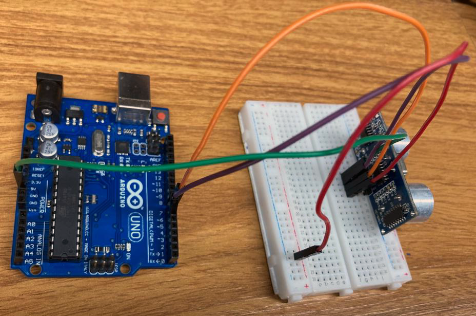
Finally, put it all together:
4. Prototype Structure
We made a really simple structure just for better handling and showing.
We used three 60x30cm MDF boards, designed a box in MakerCase and adapted in Adobe Illustrator to laser cut it in LOUCo / Porto Digital.
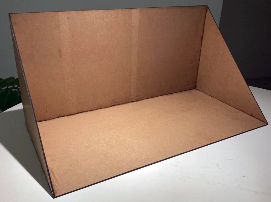
.ai archive is available below.
5. Code
We made use of Arduino IDE, FastLED library and Ultrasonic by Erick Simões library.
We made a few tests with Adafruit´s NeoMatrix library, but we didn´t use it in the code after all. We really recommend this library also, it works with FastLED and provides more features specifically for matrices. Since we are in a learning path, we decided to stick only to FastLED and keep it more simple and crude to better understanding the principles.
We took some code samples and examples in fastLED´s github and Adafruit´s github, and with coberfranc´s instructables and HeathenHacks´ project.
More details in the code´s comments below.
Expanded Technical Details
Physical RGB Canvas: 32x16 RGB P10 Matrix
Standard single-color MAX7219 matrices are child's play; they use simple SPI. The HUB75 P10 RGB LED Matrix is commercial billboard architecture! It does not have an onboard driver IC holding the image! The Arduino programmer must explicitly write highly optimized, aggressive C++ mapping arrays that violently strobe thousands of Red, Green, and Blue pixels hundreds of times per second (Multiplexing) just to prevent the panel from fading to black!
The HUB75 Timing Nightmare (RGBmatrixPanel.h)
You literally use exactly 13 Pins on the Uno just for the display!
- The matrix requires massive arrays of
R1, G1, B1andR2, G2, B2along withA, B, C, D (Row Selectors)and crucially theCLK, Latch, and Output Enable. - The Uno
loop()is practically empty. The Adafruit<RGBmatrixPanel.h>library utilizes brutal Timer Interrupts in the background! - The internal 16MHz ATmega clock literally devotes 40% of its entire CPU capacity purely to pushing the HUB75 signal, leaving only 60% of the processing power left for the user's C++ code!
- The Visual Injection: Because the panel is pure RGB, you can draw phenomenal shapes seamlessly:
// Explicit RGB color generation!
uint16_t crimsonHex = matrix.Color333(7, 0, 0); // Max Red, Zero Green, Zero Blue!
matrix.fillScreen(0);
matrix.fillCircle(16, 8, 5, crimsonHex); // Execute drawing the geometric primitive!
Marrying the HC-SR04 Telemetry
Drawing a flat image is boring. The project creates a terrifying, massive Distance Radar dynamically!
- The code uses ping pulses from an HC-SR04 Ultrasonic Sensor.
- If
distance < 10cm, the logic brutally wipes the screen:matrix.fillScreen(matrix.Color333(7,0,0));(FLASHES BLOOD RED!). - If
distance > 50cm, it executes:matrix.fillScreen(matrix.Color333(0,7,0));(GLOWS GREEN!). - The Arduino acts as the supreme logic controller, merging external kinematic sonar physics directly into extreme HUB75 RGB multiplexing arrays simultaneously!
HUB75 High Current Hardware
- Arduino Uno/Mega (Mega is wildly preferred! The massive HUB75 RGB color arrays consume a staggering amount of
SRAM. The Uno's 2KB limit means you can barely execute font libraries without the chip physically crashing in half!). - Large 32x16 or 64x32 P10/P6/P3 RGB Matrix Panel.
- A Massive 5V 10-Amp Power Supply Block. (Do NOT plug a massive RGB panel into USB power. If the screen goes full white, 512 LEDs drawing 20mA each equals 10 Amps! It will instantly explode your PC USB controller!).