To start using an RGB Led you have to know the pins of the led as follows;
DATASHEETLEDRGB
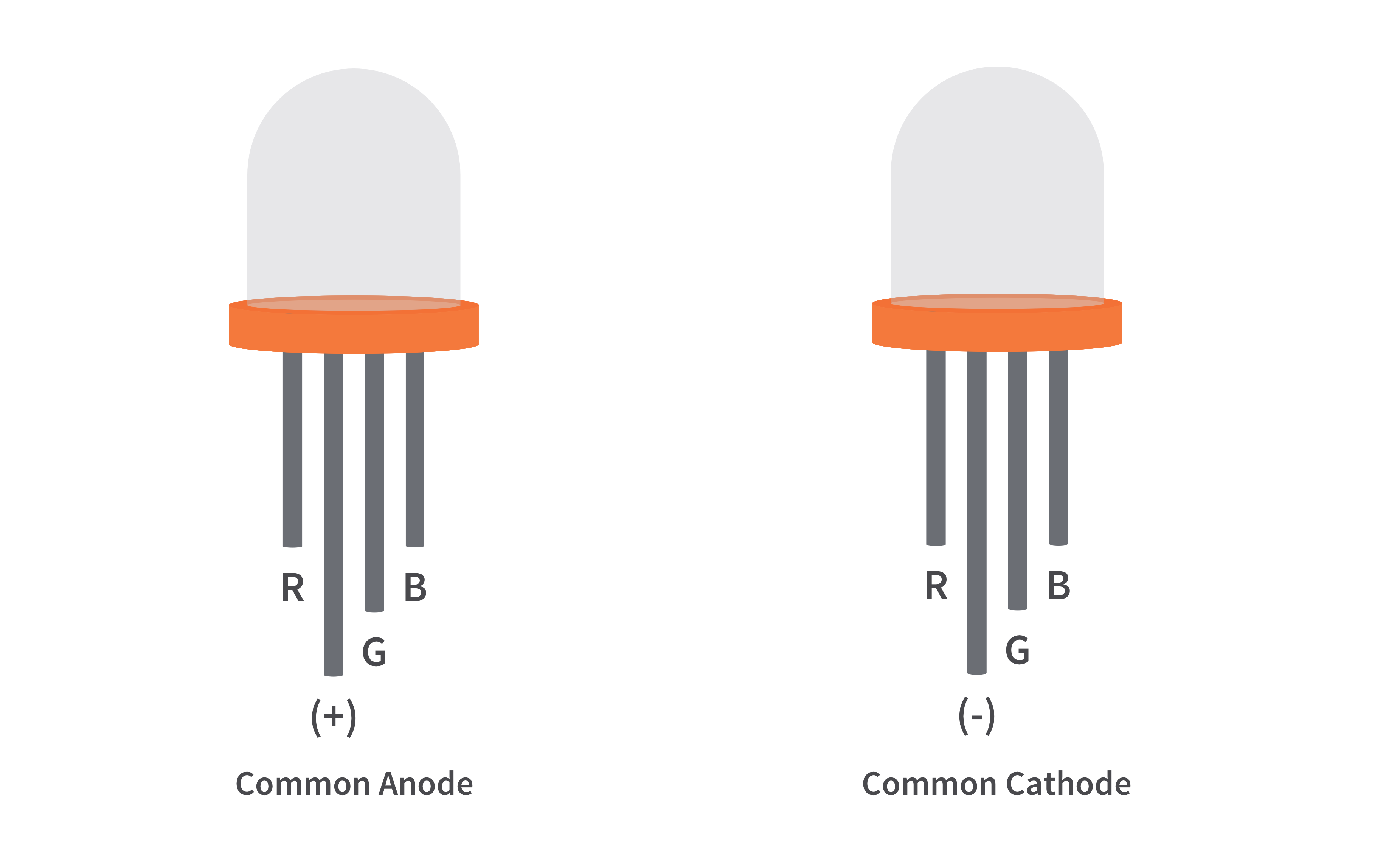
Now for this project that I made, I used a common cathode RGB led.
- Connect pin R (RED) to pin number 6 of the Arduino board.
- Connect pin GND to pin GND of the Arduino board.
- Connect pin G (Green) to pin number 5 of the Arduino board.
- Connect pin B (Blue) to pin number 3 of the Arduino board.
- Andfinallyuploadthecode:)
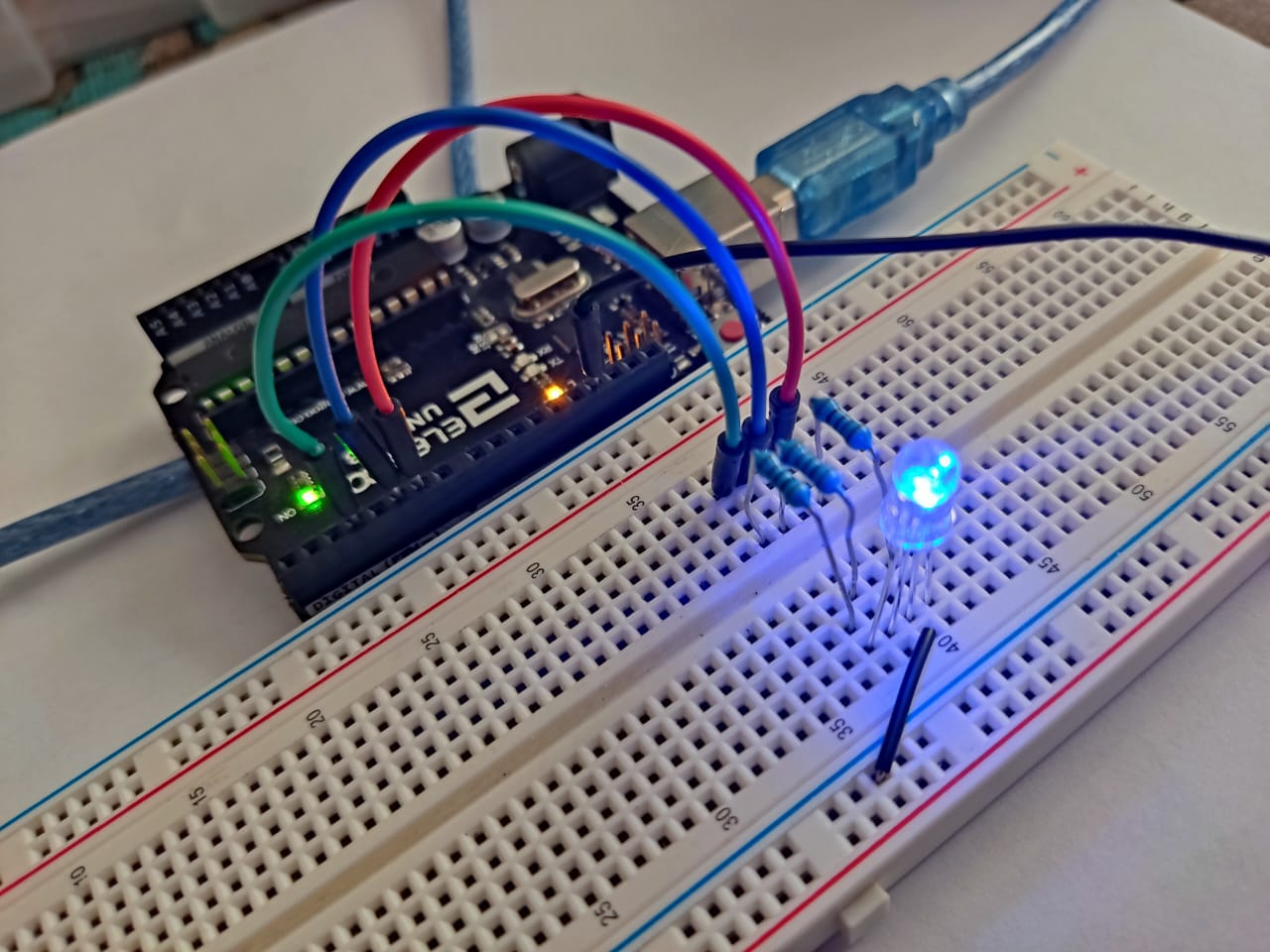
This would be the final result if all the connections were followed.
Technical Details: PWM Color Synthesis
This project explores the physics of light through digital Pulse Width Modulation (PWM).
- Analog Output Mapping: The Arduino sends 8-bit PWM signals (values from 0-255) to the Red, Green, and Blue pins of the common-cathode RGB LED. By independently varying the duty cycle (brightness) of each color channel, millions of distinct colors can be synthesized.
- Dynamic Fading Algorithm: The code can include a software "Color Loop" that cycles through the HSL (Hue, Saturation, Lightness) color space, creating smooth, rainbow-like transitions instead of abrupt color changes.
Advanced Calibration
- Gamma Correction: For a more advanced version of this project, a lookup table can be implemented to apply gamma correction. This compensates for the non-linear way human eyes perceive brightness, making color fades and dimming appear significantly smoother and more natural.
Thank you for taking the time to make my project, I hope you like it. :)
It's my first time uploading projects here, so sorry if I missed a step.
My Tinkercad: https://www.tinkercad.com/users/gfOgEin92Vh?category=circuits&sort=likes&view_mode=default