Introduction and Inspiration
Hello again everyone. I have recently got a Sparkfun Sound Detector, and the first thing I did was use the official Sparkfun Sound Detector Hookup Guide to test my sound detector. After that, I wanted to add a bit of a challenge - was it possible to use regular LED lights to create a sound visualizer based on the Sound Detector's readings? That train of thought led me to this project - the video is below -
Step 1: Component Introduction
For this project, you will need
- an Arduino board (I chose the Mega 2560)
- jumper wires
- Breadboard
- Sparkfun Sound Detector
- Red LED
- Blue LED
- Yellow LED
Here are some tutorials on how to use the components
Now, let's move on to the hardware wirings.
Step 2: Hardware Wiring
Ok, so first, let's analyze the sound detector. First things first, solder the headers on if you bought the un-soldered one.
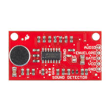
Notice that there are 5 pins - Audio, Envelope, Gate, VCC, and GND. Audio, Envelope, and Gate are all inputs, with VCC being power and GND being Ground. For this project, we will follow the hookup of Sparkfun's Sound Detector hookup guide, which uses all pins except for Audio.
According to SparkFun,
"Connections:
The Sound Detector is connected to the Arduino as follows:
(Sound Detector -> Arduino pin)
GND → GND
VCC → 5V
Gate → Pin 2
Envelope → A0"
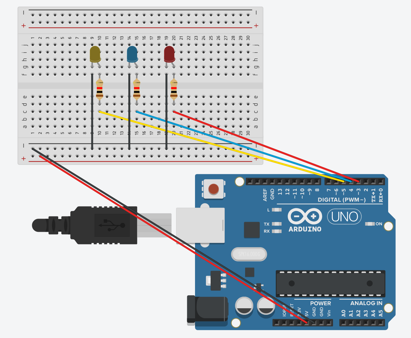
Once you have that wired, the rest should be simple. Each LED has a longer positive end and a shorter negative end. Each negative end goes to GND, and the positive end goes to a Digital IO pin through a 220-ohm resistor. In my project, Digital IO pin 5 is the yellow led on left end, Digital IO pin 4 is the center blue led, and digital IO pin 3 is the red led. Here is a circuit for the LEDs.
When you have finished the LEDs and the Sound Detector hookup, move onto the coding section.
Step 3: Software and Coding
Copy and paste this code into the Arduino IDE.
//Use Sparkfun's Sound Detector Guide to Create a Sound Visualizer
// Define the Pin connections
#define PIN_GATE_IN 2
#define IRQ_GATE_IN  0
#define PIN_LED_OUT 13
#define PIN_ANALOG_IN A0
void soundISR()
{
 int pin_val;
 pin_val = digitalRead(PIN_GATE_IN);
 digitalWrite(PIN_LED_OUT, pin_val);
}
void setup()
{
 Serial.begin(9600); //Starts Newline Baud Connection
 pinMode(PIN_LED_OUT, OUTPUT); //Setting builtin LED for the SOUND detector as OUTPUT
 pinMode(PIN_GATE_IN, INPUT); //Setting the Gate Pin as input
 attachInterrupt(IRQ_GATE_IN, soundISR, CHANGE);
//Set LED Pins as OUTPUT
 pinMode(5, OUTPUT);
 pinMode(4, OUTPUT);
 pinMode(3, OUTPUT);
}
void loop()
{
//Sets the LEDs to OFF
 digitalWrite(5, LOW);
 digitalWrite(4, LOW);
 digitalWrite(3, LOW);
 int value;
 value = analogRead(PIN_ANALOG_IN);
 Serial.println("Volume Value: ");
 if ((value>=10) && (value <=20))
 {
   digitalWrite(5, HIGH);
   Serial.print(value);
   Serial.println("LOW VOLUME");
 }
 else if ( (value > 20) && (value <= 30) )
 {
   digitalWrite(4, HIGH);
   digitalWrite(5, HIGH);
   Serial.print(value);
   Serial.println("MEDIUM VOLUME");
 }
 else if (value > 30)
 {
   digitalWrite(3, HIGH);
   digitalWrite(4, HIGH);
   digitalWrite(5, HIGH);
   Serial.print(value);
   Serial.println("HIGH VOLUME");
 }
 else {
   Serial.println("LITTLE/NO VOLUME DETECTED");
 }
 delay(1000);
}
Upload the code. If you get an error message, copy and paste it in a comment. That's it for now. Thanks!
Expanded Technical Details
Acoustic Signal Processing
This project translates physical sound waves into vibrant, rhythmic lighting patterns, acting as a high-speed "Visual Equalizer."
- Analog Audio Sampling: The Arduino samples the signal from the Sound Detector's envelope output using a high-frequency analog polling loop. It identifies "Peaks" in the signal to determine the current loudness, which is then mapped to the LEDs as shown in the code.
- Addressable LED Intensity (Advanced Concept): For more advanced versions, you could use a NeoPixel strip or array. The loudness can be mapped to the length of a "Level Meter" or the brightness of the colors, providing near-instant visual feedback that matches the music's beat.
Advanced Features
- FFT Frequency Breakdown: (Advanced version) You could use the Fast Fourier Transform (FFT) library to split the sound into Bass, Mid, and Treble, allowing the Arduino to change different sections of an LED strip based on the musical frequency, creating a true spectrum analyzer.