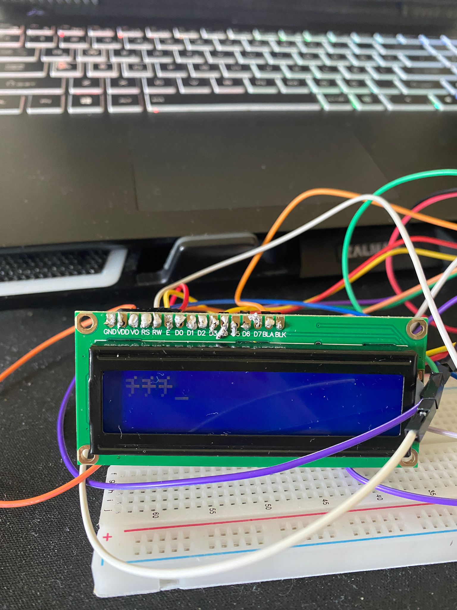
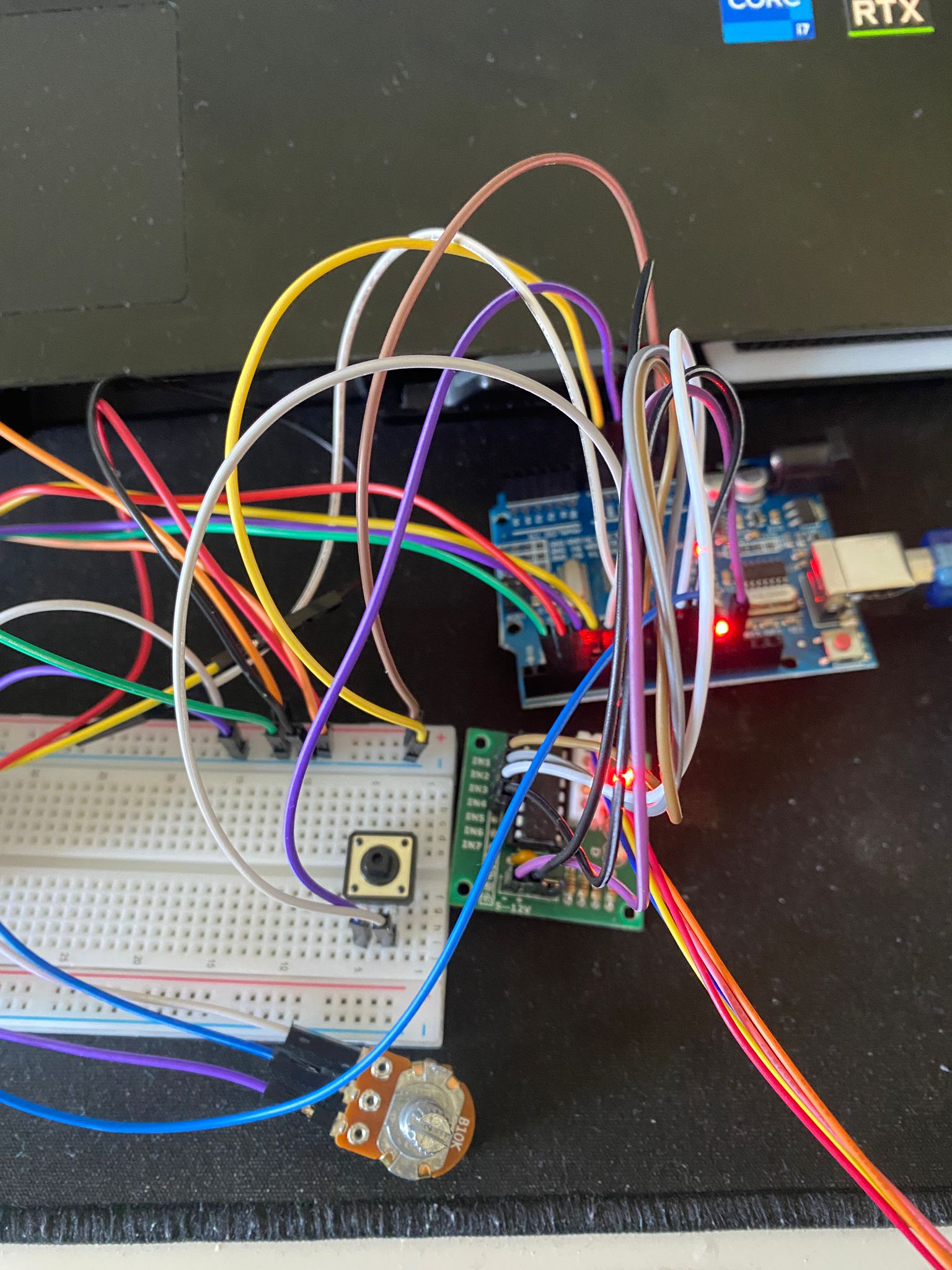
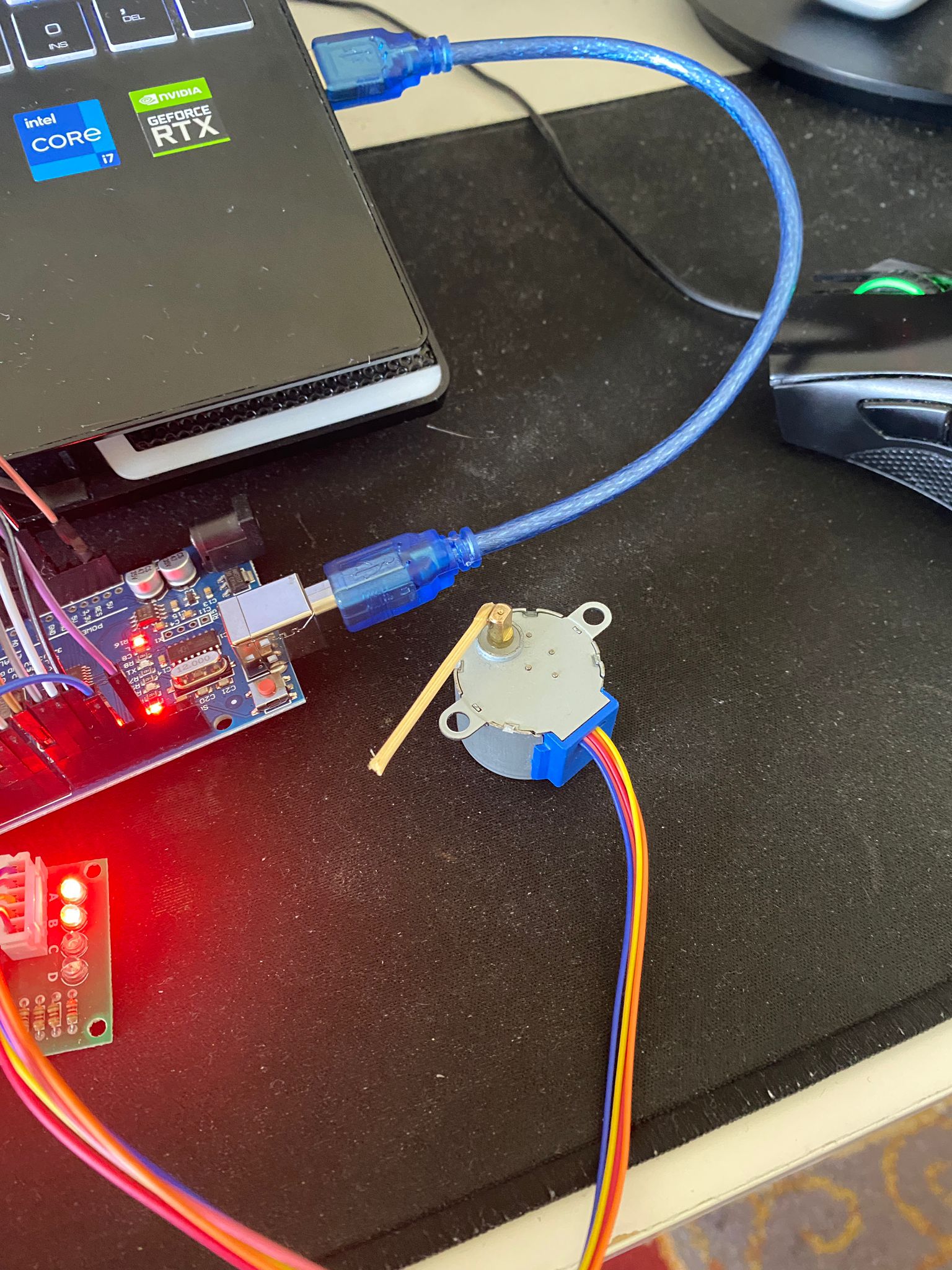
This project was created to build a locking system using an Arduino Uno. When the button is pressed a specific number of times, the locking mechanism rotates 90 degrees in one direction. Pressing the button the same number of times again rotates it 90 degrees in the opposite direction.
Digital Warden: The Basic Locking System
The Locking System is an entry-level security project that moves away from physical brass keys to digital authentication. It is the perfect starting point before building biometric (fingerprint) or RFID (keycard) scanners.
Core Authorization Loop
The project focuses on creating a secure validation loop in C++:
- Standby: The system is locked (Red LED ON, Relay OFF).
- Input: A specific trigger is sent—this could be a secret push button sequence or a command sent via the Serial Monitor on your PC.
- Validation: The Arduino checks the input against a hardcoded string or integer password.
- Action: If correct, the Arduino sets a digital pin HIGH to trigger a relay, opening the electronic lock. If incorrect, it delays (to prevent brute-forcing) and sounds an alarm.
Necessary Components
- Arduino Uno: The security processor.
- 12V Electronic Cabinet Lock (Solenoid Tongue): A real-world electronic latch.
- 1-Channel Relay or Power MOSFET: To isolate and switch the 12V lock.
- LEDs and Buttons: For user interfacing.
Exploring Security
While a hardcoded password is fine for learning, you'll quickly realize its limits. This project serves as a blank canvas; once you understand the Relay/Lock dynamic, you can easily rip out the "Button" code and replace it with an RFID reader or Bluetooth module, creating a truly modern smart-lock.