In this project we are trying to build a pyranometer, a tool that measures solar radiation in w/m2. This tool can replace expensive commercial tools, being a lower cost solution.
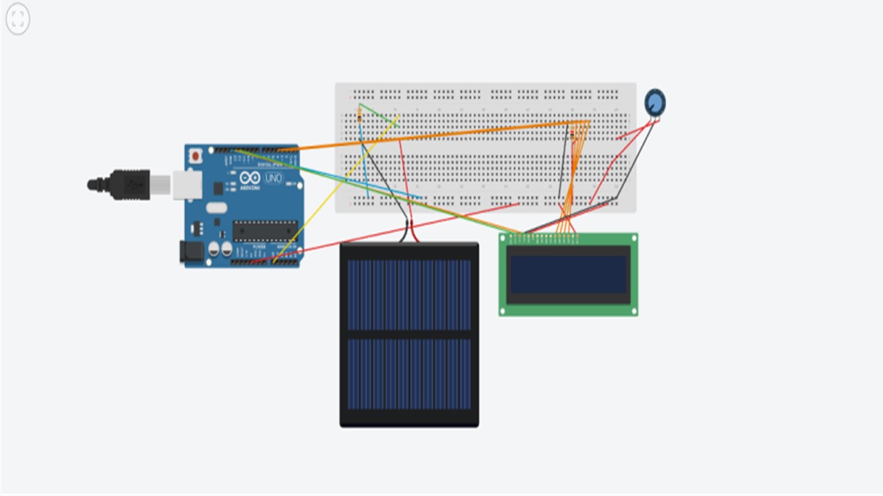
Experimentation on the connections can be done via Tinkercad, as shown in the following picture.
EXPANDED TECHNICAL DETAILS
While a standard light-dependent resistor (LDR) can tell if it's "bright" or "dark", it cannot be used for scientific energy calculations. This Solar Radiation Monitor involves interfacing a sensor to calculate solar irradiance.
A true pyranometer uses a thermopile (a stack of thermocouples under a glass dome). The sun beats down on it, generating a tiny, proportional voltage.
- The Problem: A pyranometer outputs a microscopic signal—perhaps
10 microvoltsper Watt of sunlight. The standardanalogRead()on an Arduino Uno cannot read microvolts; it can barely read millivolts. It will just output0. - The Solution: For a professional build, you must use a high-precision, external Analog-to-Digital Converter (ADC), like the ADS1115 (16-bit) or HX711 (24-bit).
The Math and Data Logging
Using an external ADC like the ADS1115 connected via I2C, you can amplify the pyranometer signal.
- The Arduino reads the amplified decimal value.
- You multiply it by the specific calibration factor provided on the sensor's factory datasheet.
- The result is the precise Solar Irradiance in
W/m². - For long-term analysis, this data can be time-stamped via an RTC module and saved into a CSV file on an SD Card module for agricultural or energy studies.
Necessary Components for an Advanced Build
- Arduino Uno/Nano.
- Pyranometer Sensor: E.g., Apogee SP-series or a thermopile equivalent.
- ADS1115 16-Bit I2C ADC Module: The core component for accurate measurement.
- SD Card Datalogger module with RTC (Real Time Clock).
Assembly Steps
Then we connect the Arduino Uno board to a computer and through the Arduino IDE platform the given code is entered.
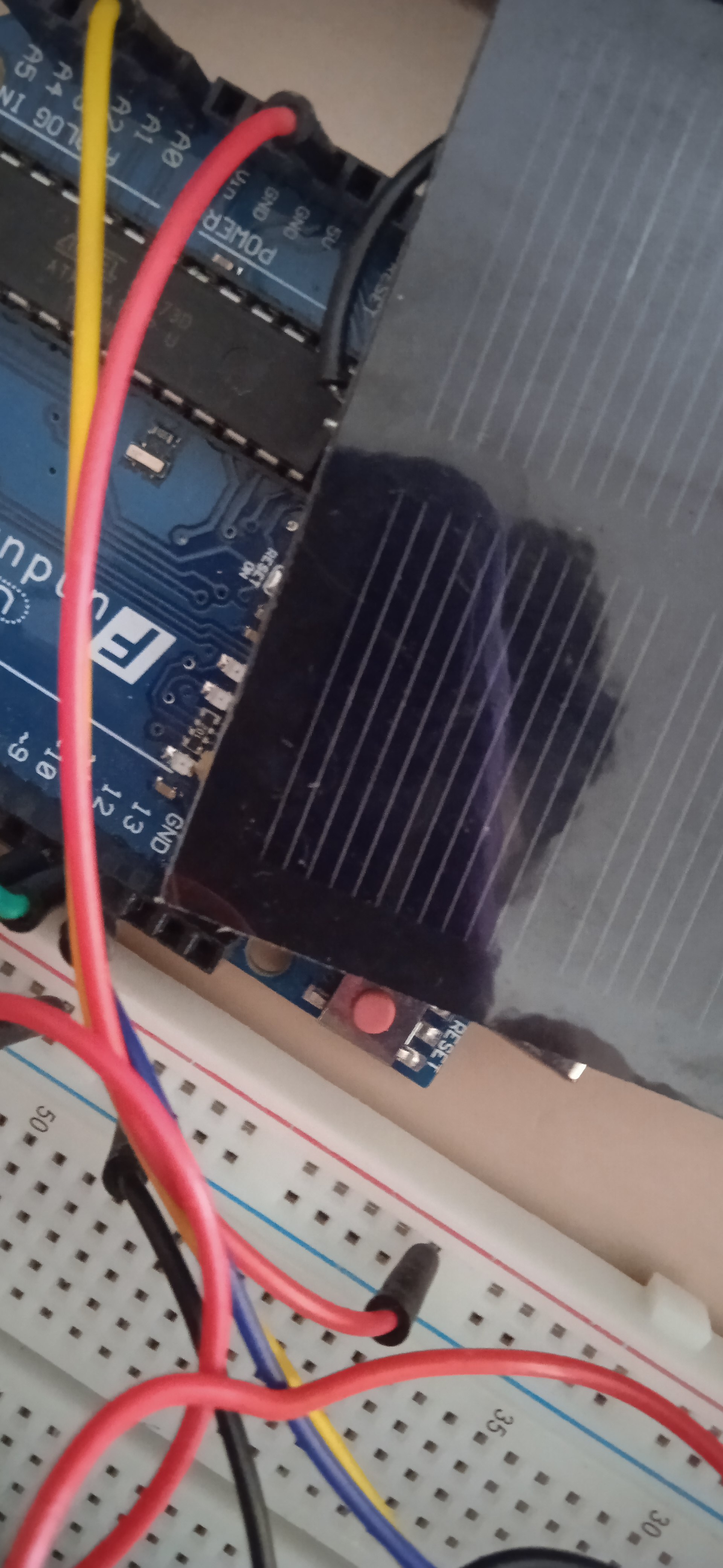
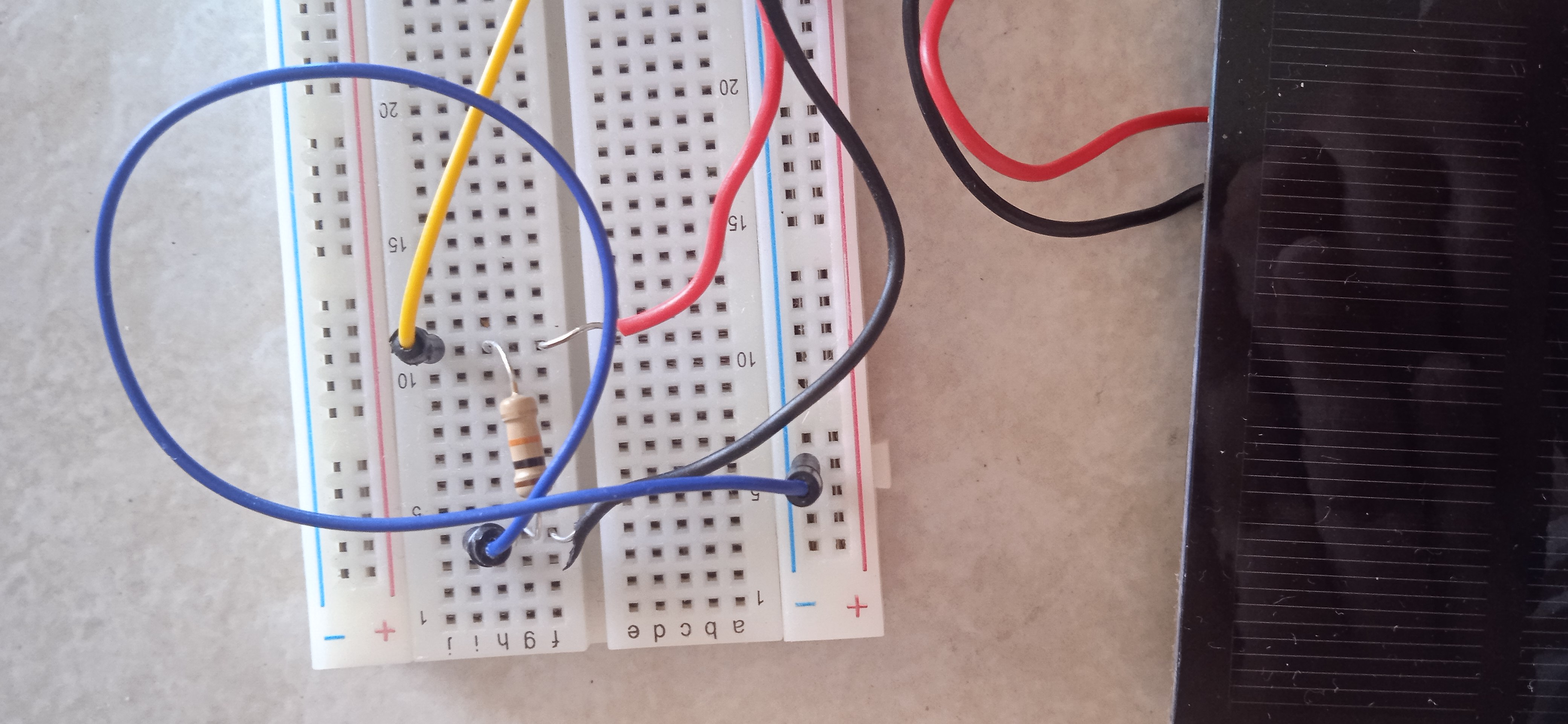
Our first step is to connect the yellow cable, which connects the breadboard with the A0 port of Arduino as shown in the picture
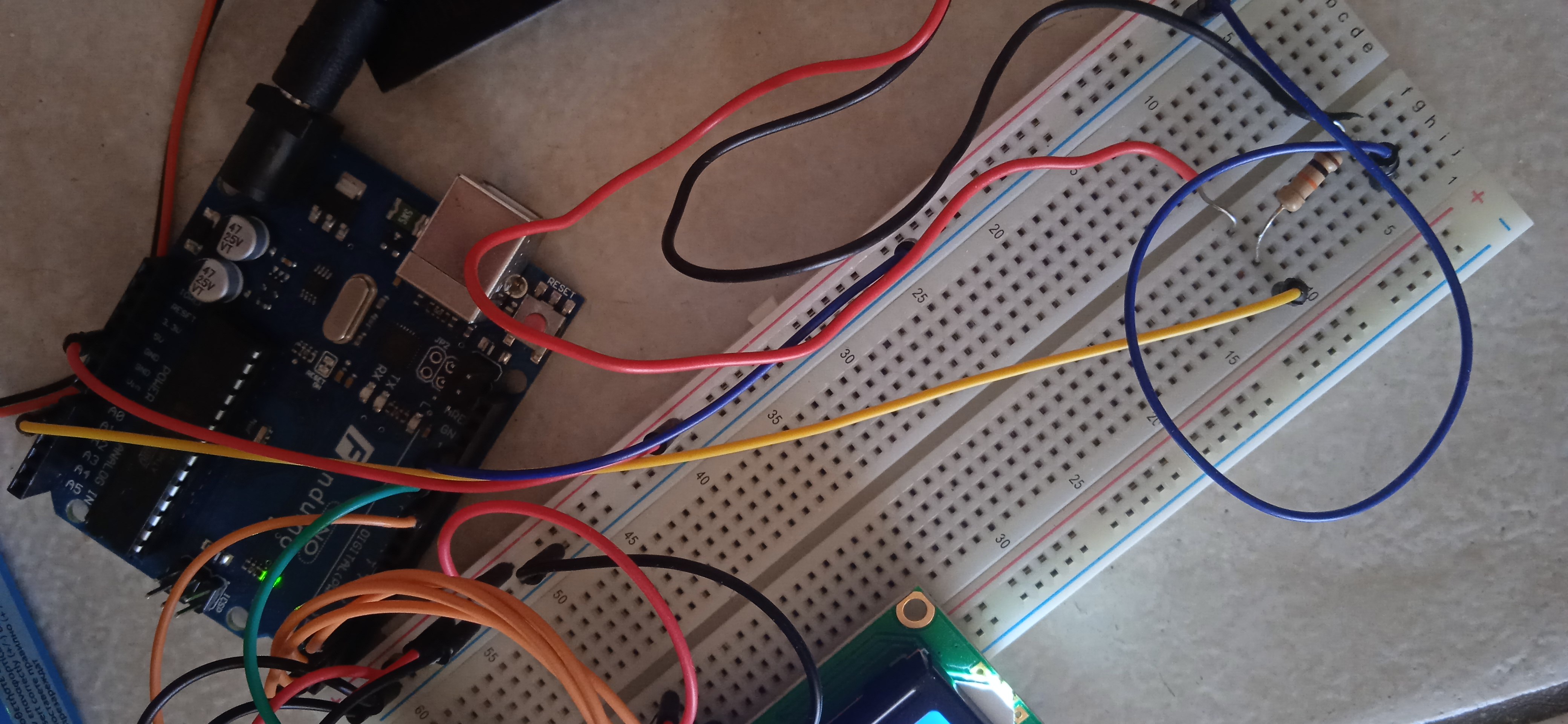
- The second step is to connect the short blue cable on the breadborad with the ground port of Arduino as shown in the picture
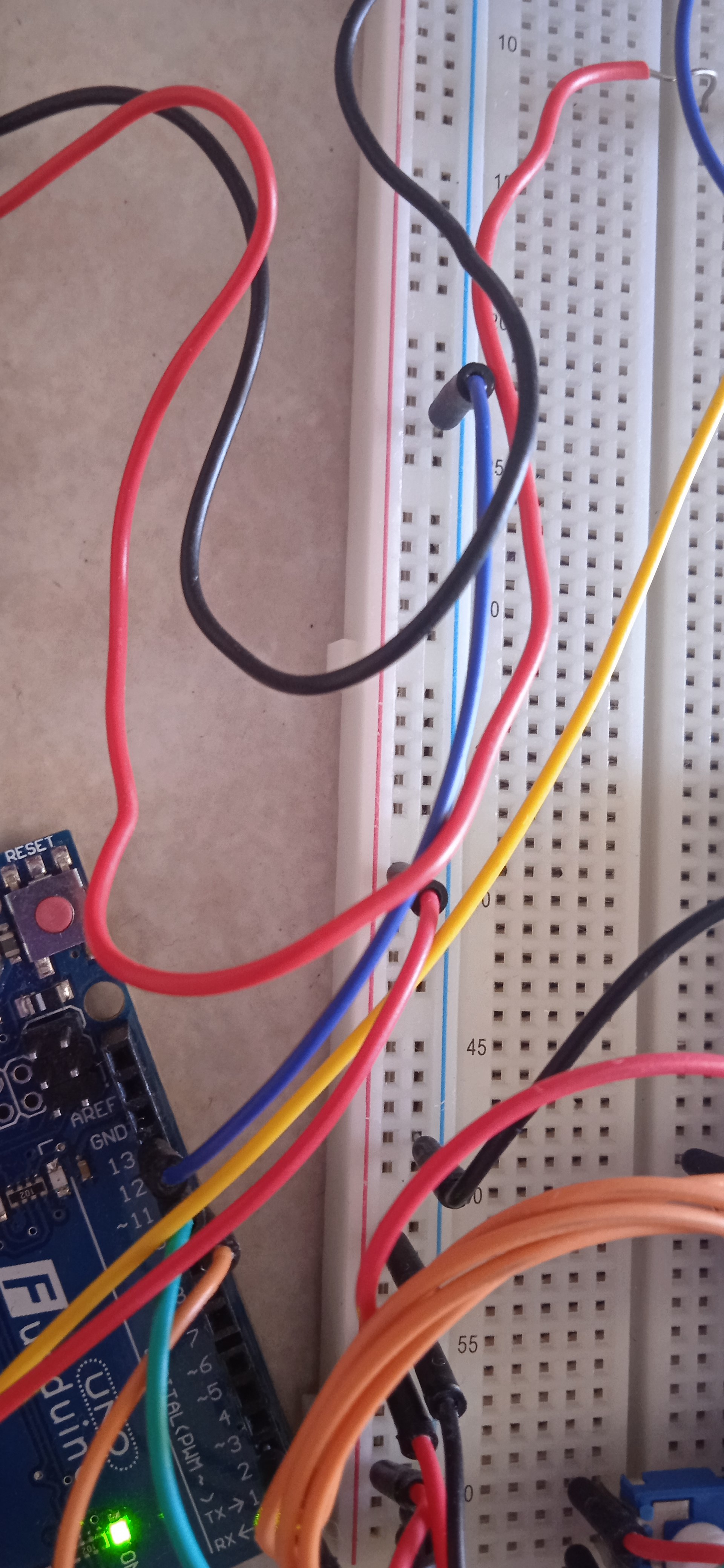
We also connect the short red cable which connects the breadboard with the 5V port of Arduino as shown in the picture
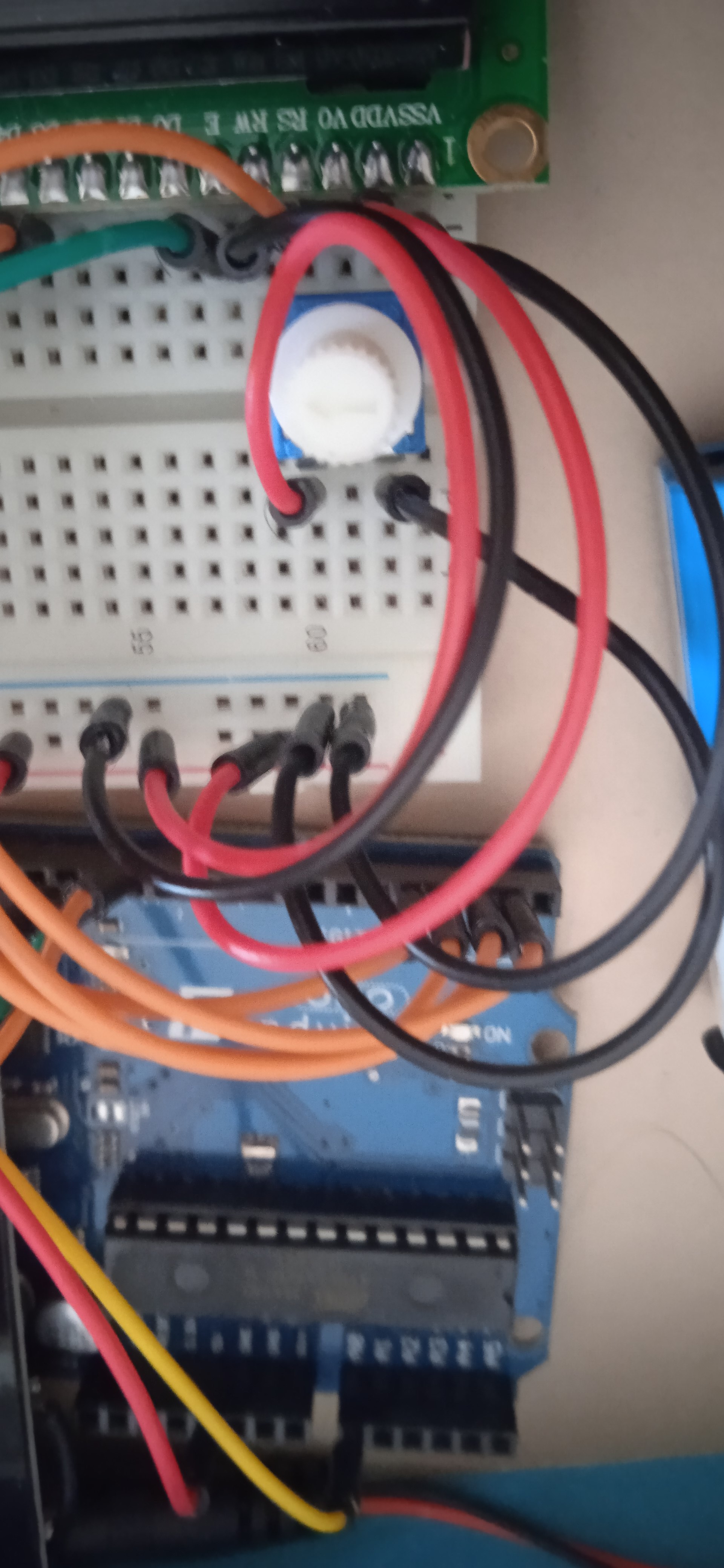
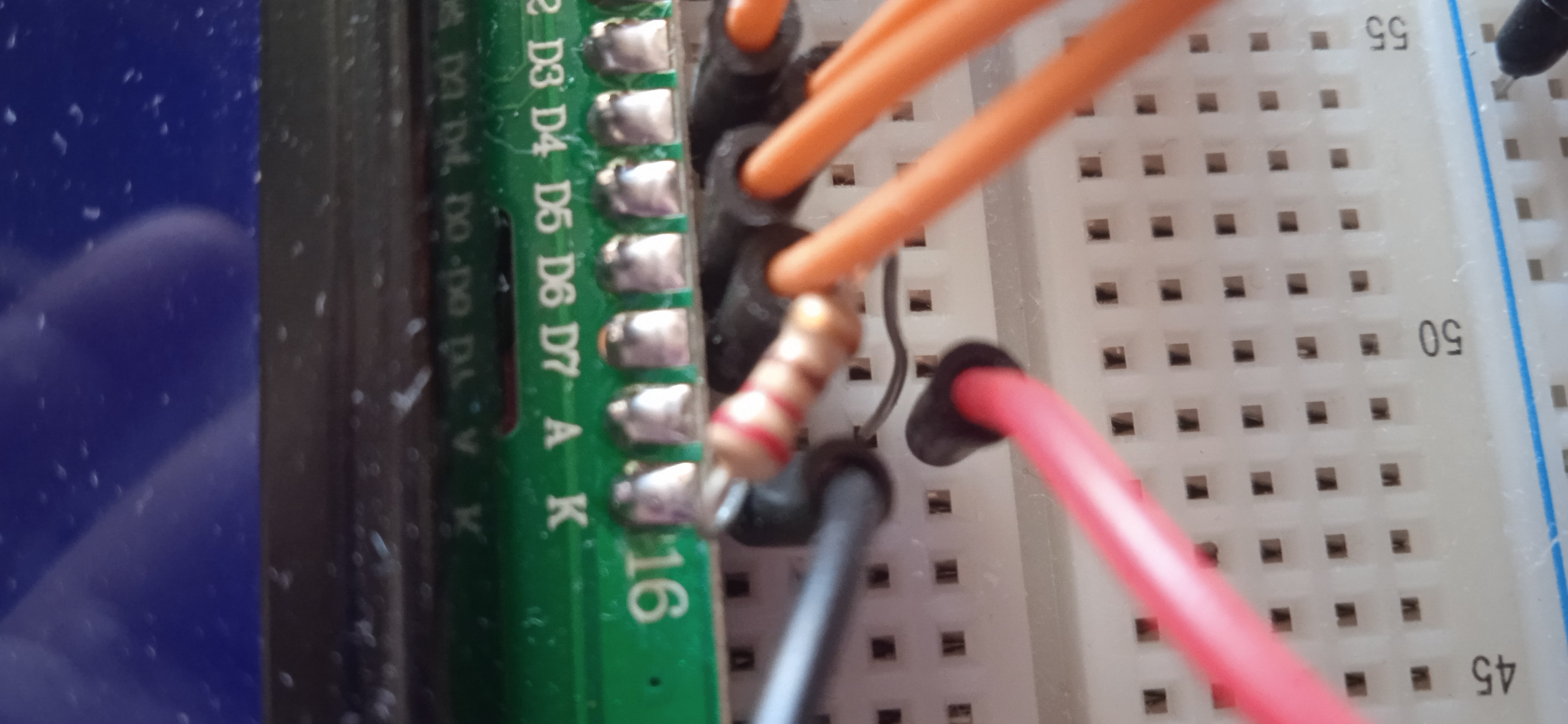
- Now we focus at the orange cables connecting the breadboard with Arduino Uno. One connects the Digital 12 of Arduino with RS of the LCD screen. The other connects the Digital 4 port of Arduino with D4 of the LCD screen. The other connects the Digital 3 of Arduino with D5 of the LCD screen. The other connects the Digital 2 of Arduino with D6 of the LCD screen. The last one connects the Digital 1 of Arduino with RS of the D7 screen.
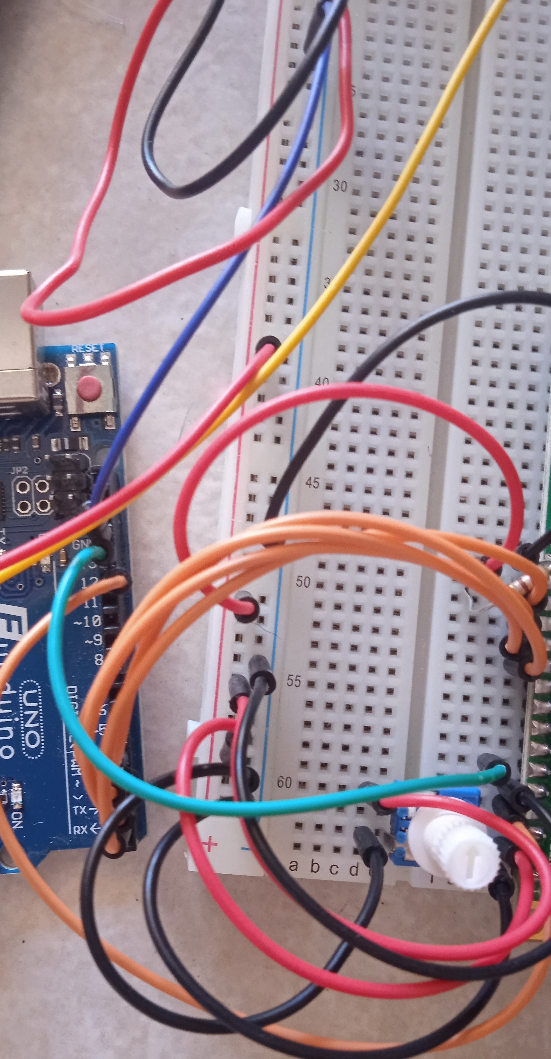
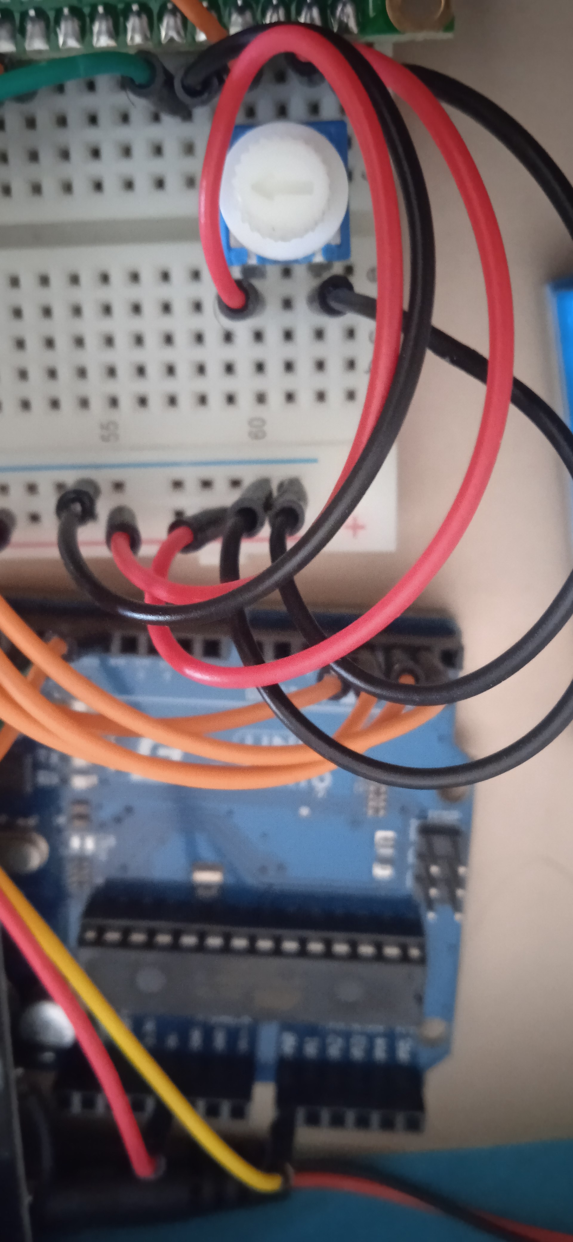
- The fourth step is to connect the potentiomenter and the 10 kΩ trimmer CA9 with the breadboard as shown in the image below. Also the green cable is used to connect the potentiometer with the Digital 13 port of Arduino.
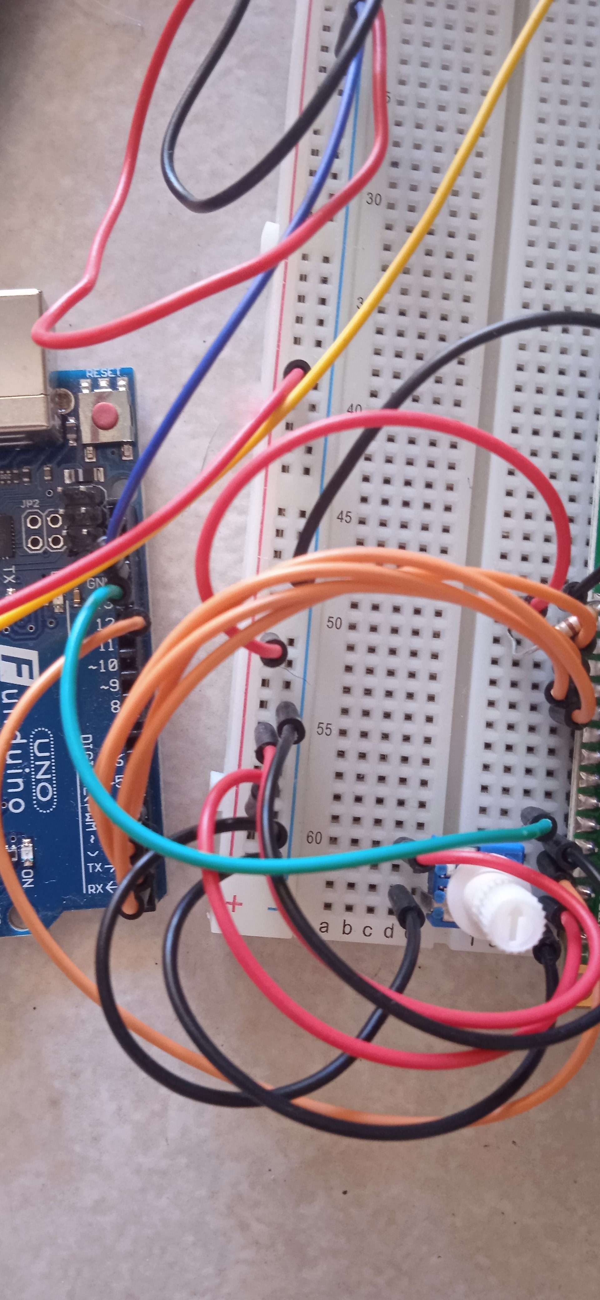
We can also connect the red and black cables on the breadboard as shown in the picture.
5.The fifth step includes the connection of the two resistances as shown below (Resistor 10 kΩ-Resistor 220 ohm). We can also connect the solar panel with the breadboard. The connection is shown in the second picture below.
- The final step includes the connection of the battery (Alkaline 9V) with the Arduino Uno platform using the Arduino 9V Jack adapter.
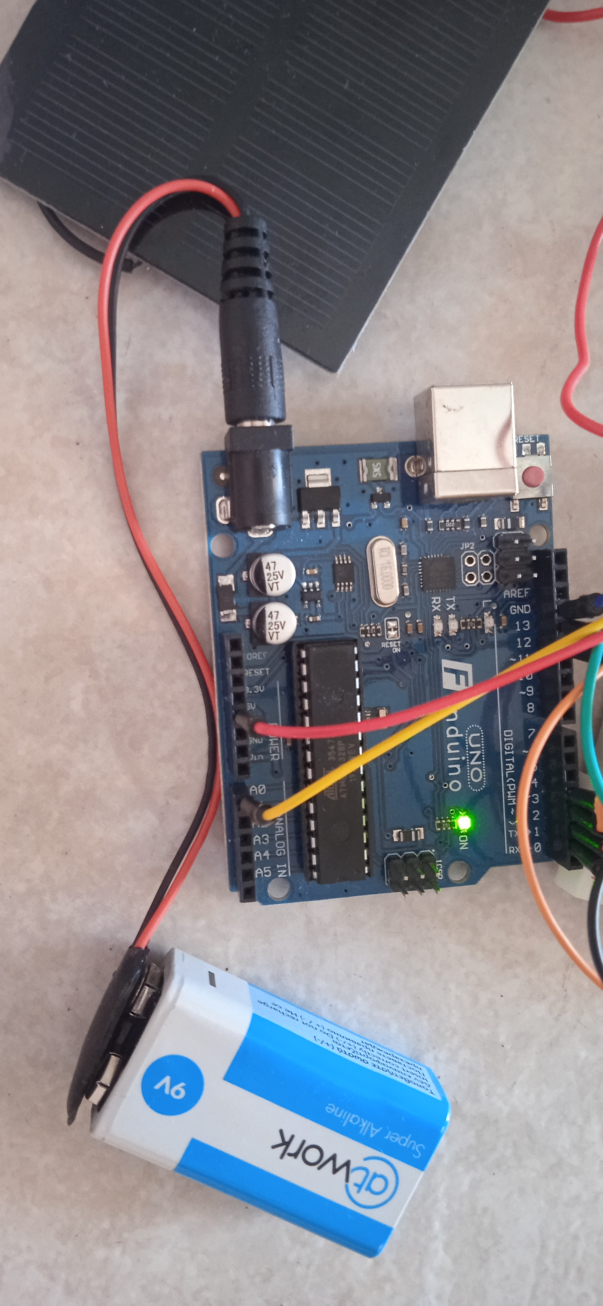
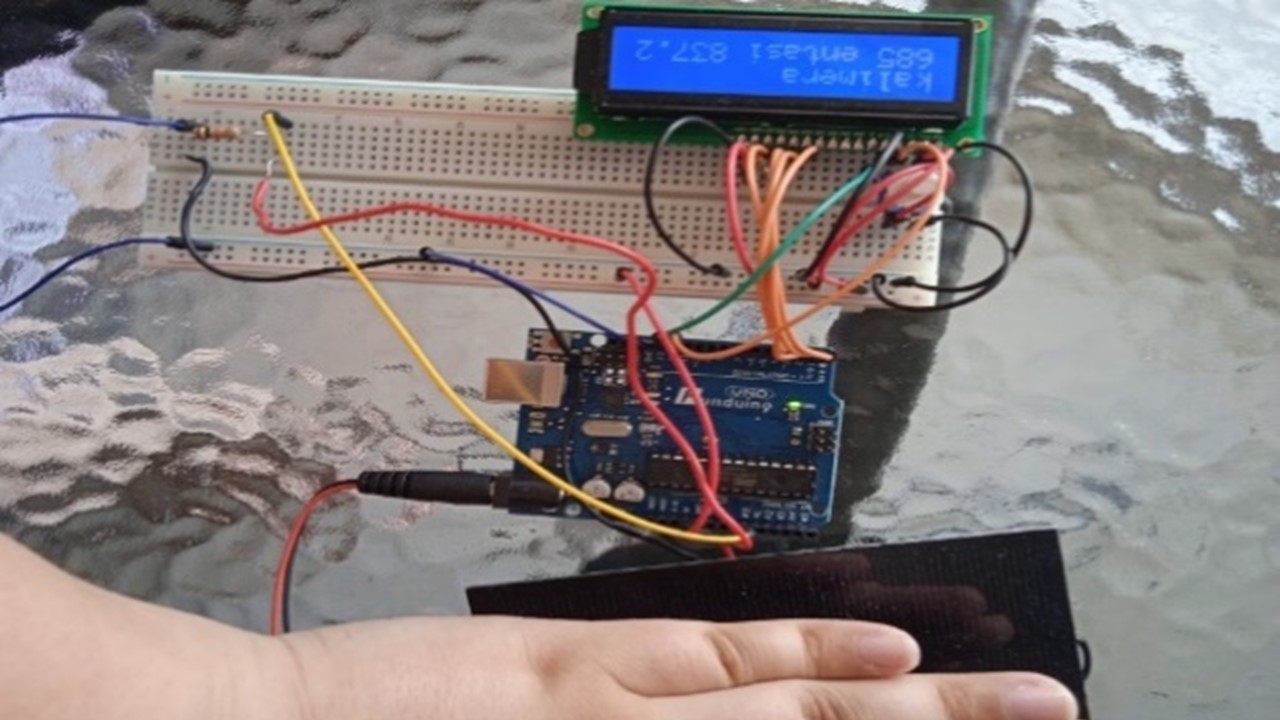
The device shall then be set up and the measurement is being made at the intensity of the electromagnetic radiation per unit area measured in W/m2. The complete device of the pyranometer is shown in the picture.
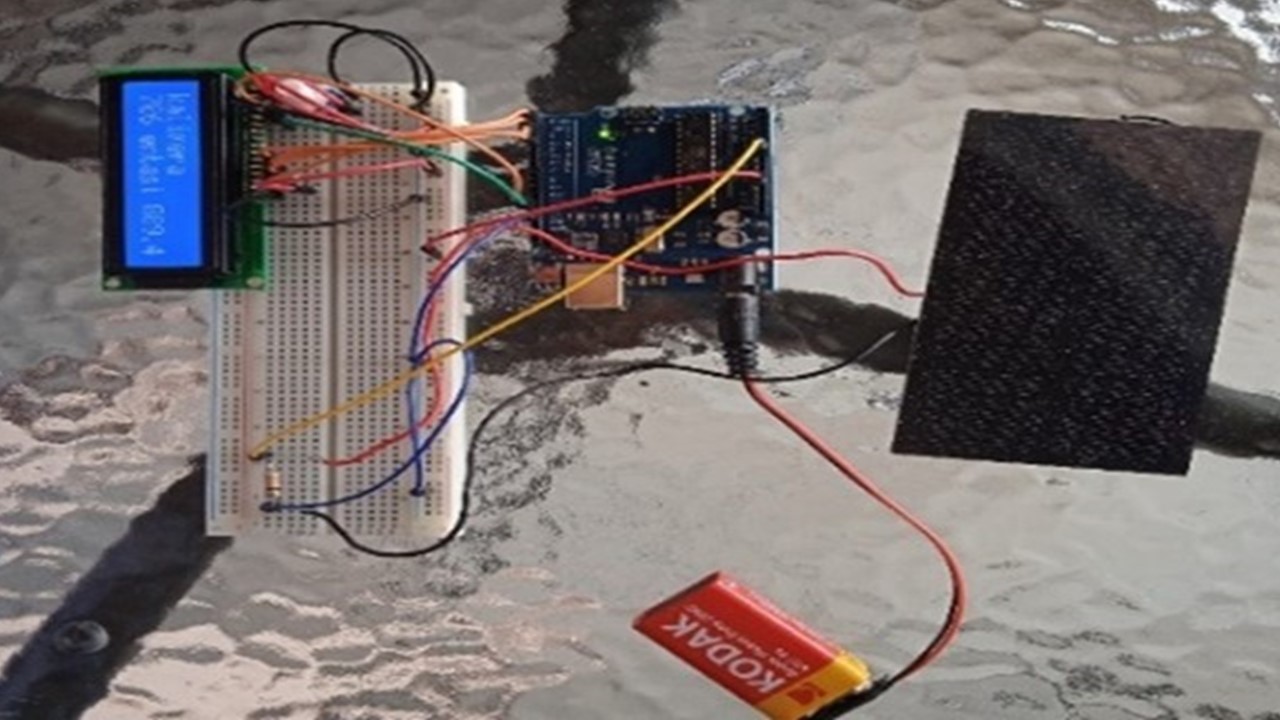
The pyranometer is placed on a horizontal surface measuring the total solar radiation incident on it. Finally, as an indication, a part of the solar panel can be shaded and the changes in the measurements can be observed.