This is an upgrade to my first Hydroponics Controller project which was based on the Uno and acted as my first attempt at arduino programming.
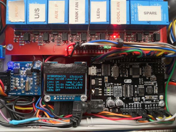 Uno based Hydroponics Controller.
This upgrade replaces the Uno with the R3 ATmega2560+ESP8266, also I have included the DFrobot SIM7000C Arduino NB-IoT/LTE/GPRS expansion shield and a few more sensors.
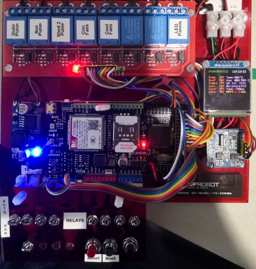 MEGA + WiFi based Hydroponics Controller.
The original control system was based on independent electronic timers without any status reporting or monitoring. This was not acceptable when I was away from the shed for more than a couple of days, as a pump failure or major leak would likely kill any plants, this happened a couple of time over the xmas holidays.
Some lessons learnt from my first project :
1. Always have a backup copy of your working program before you start. Nothing worse then a good compile but strange program behaviour and you are sure nothing changed? Normally this was me dropping tools or food on the keyboard.
2. When using a MPPT solar charge controller for your VCC supply, use a step-down DC-DC converter and set to 9-10VDC as this will save the 5V regulator chip as the MPPT can supply close to 14VDC on a sunny day ( I replaced a couple of regulator chips).
3. Don't make too many changes before compiling and running, very frustrating to fault-find when you have made several changes and things don't work.
4. Read up on the products you are using as you may need to consider compatibility issues such as using the SIM7000C shield with the MEGA or serial port conflicts.
5. Think about EMI and current surges when using inductive loads such as pumps and fans, also if you have multiple power sources ensure you have a common GND.
The controller activates pumps and fans based on the Boolen AND operation. In the example below the Pump will operate when the real time clock (RTC) time is in the range of 6 to 21 hours and 0 to 4 minutes, so if the time is 07:00:00 the pump will run for 5 minutes as the run time is from 07:00:00 to 07:04:59.
// hydroponic gully pump timer

   if (nH >= 6 && nH <= 21 && nM >= 0 && nM <= 4 )
 {      digitalWrite (Pump, HIGH);
 display.setColor(RGB_COLOR16(255, 255 , 255));
 display.printFixed(0, 40, "Pump1 ON " );
 delay(400);    }
Flow sensors will monitor pump flow rates and will issue alerts when flows are slow or not detected, this is important as a failing pump can drain the battery due to excess current draw and a dead pump means the plants are not receiving any nutrients.
The code below checks a modified voltage from the flow sensor and if the value is less than 1 volt and the pump is active (High) and the manual switch is off (High), an alert is sent to the local display and the Firebase Realtime Database. Also a backup pump (AuxPump) will activate.
if ((flow1V < 1)
       && (digitalRead(Pump) == HIGH)
       && ((digitalRead(S1)) == HIGH ))
  { display.setColor(RGB_COLOR16(255, 255 , 255));
    display.printFixed(104, 40, "FAIL");
    digitalWrite (AuxPump, HIGH);
    display.printFixed(0, 10, "Alert - AUX ON    ");
    display.setColor(RGB_COLOR16(255, 0 , 0));
    display.printFixed(0, 50, "AUX P ON ");
    dM[2] = "Gully1 - ALARM NO FLOW" + dH[3];
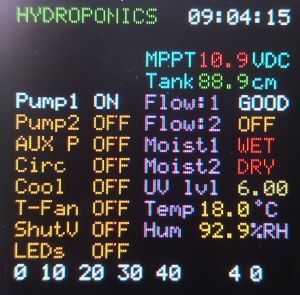
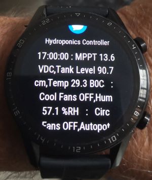
The image below shows Pump1 activation with good flow, note the MPPT voltage text is red indicating a low voltage level which is expected when the pump is activated. The use of colour to stress system status is very useful as a quick way to check for issues.
A voltage divider network consisting of 3 resistors is placed across the input to the DC-DC down converter to reduce the MPPT voltage by a third before been read by an analogue input. A calibration value and x3 multiplier is applied to the analogue voltage reading to represent the actual MPPT voltage.
 // read load voltage * cal factor * voltage divider mult
    char LoadValue[1];
    float Volts = ((analogRead(BattV)) * .0047 * 3);
    dtostrf(Volts, 0, 1, LoadValue);
A dual ultrasonic sensor module is used to measure the nutrient tank level, the ping and echo time is converted to distance as part of the library function. The code below subtracts the distance to nutrient ( the lower the level the longer distance for the ping and echo to travel) from a fixed value which represents a full tank. I placed a fan on top of the tank to circulate the air inside the tank as condensation will start to corrode the ultrasonic sensor.
 // read nutrient tank level
    char Lbuf[1]; float uS = sonar.ping();
    float Lvl = (111 - (uS / US_ROUNDTRIP_CM));
    dtostrf(Lvl, 0, 1, Lbuf);
All other sensors, pumps and fans operate in a similar fashion to the above all in a sequential order with strict control over operation times to conserve battery life. A set of toggle switches are available to manually drive relays if require, these are tied to digital inputs.
Each operation produces a part of the status data message which is send to a Firebase Realtime Database via WiFi and to a cell phone via the RFrobot SIM7000C shield. Shown below is the formatting of the final data messages. Message size and syntax is vital for correct transmission to the Realtime database as is the time delays to allow AT commands to be processed by the SIM7000C.
 // send system status message to Firebird database via WiFi
    Serial3.print((dH[1]) + (dM[0]) + (dM[1])
                  + (dM[2]) + (dM[3]) + (dM[4])
                  + (dM[5]) + (dM[6]) + (dM[7])
                  + (dM[8]) + (dM[9]) + (dH[2]));

 // send system status message to cellphone.
    Text = ((dM[0]) + (dM[1]) + (dM[7])
            + (dM[8]) + (dM[4]) + (dM[5]));

    if ((nH == 17 && nM == 0 && nM == 0 && nS == 0 )
        || (digitalRead(AlmTEST)) == LOW )

    {      mySerial.print("AT+CSCA=\"+6421600600\"\r");
 delay(20);      mySerial.print("AT+CMGF=1\r");
 delay(20);      mySerial.print("AT+CMGS=\"**********\"\r");
 delay(20);      mySerial.print(Text);
 display.setColor(RGB_COLOR16(255, 255 , 0));
 display.printFixed(0, 10, "Calling **********");
 mySerial.write(0x1A); delay(500);    }
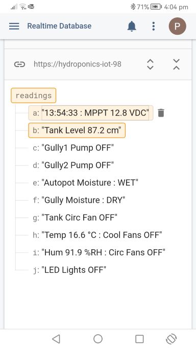 Firebase Realtime database
 Test message from smartphone
All the above is under the watchful eye of a watchdog timer which expects a full sequence to occur in under two seconds, if not it will reset the MEGA and SIM7000C. Hang-ups are most likely due to the RTC freezing, in rare cases a reset will not work as the RTC time has become invalid and a valid entry is require using the rtc.adjust statement.
// real time clock
  rtc.begin();
//rtc.adjust(DateTime(22, 12, 30, 12, 43, 00));
EXPANDED TECHNICAL DETAILS
Industrial-Scale Automation
Utilizing the Arduino Mega 2560 for its high pin count, this controller manages complex life-support systems for a large-scale hydroponic greenhouse.
- Sensory Array: Monitors EC (Electrical Conductivity) for nutrient levels, pH for water acidity, and Water Temperature via a DS18B20 waterproof sensor.
- Environmental Management: Incorporates DHT22 sensors for ambient air humidity and temperature, adjusting fans and misting systems in real-time.
Dosing & Fluid Control
- Peristaltic Pump Control: The Mega drives high-precision pumps via a Relay or PWM driver to automatically inject nutrients and pH-adjusters into the main reservoir.
- Display Hub: All critical metrics are shown on a large 20x4 I2C LCD, providing an immediate at-a-glance status report for the farmer.