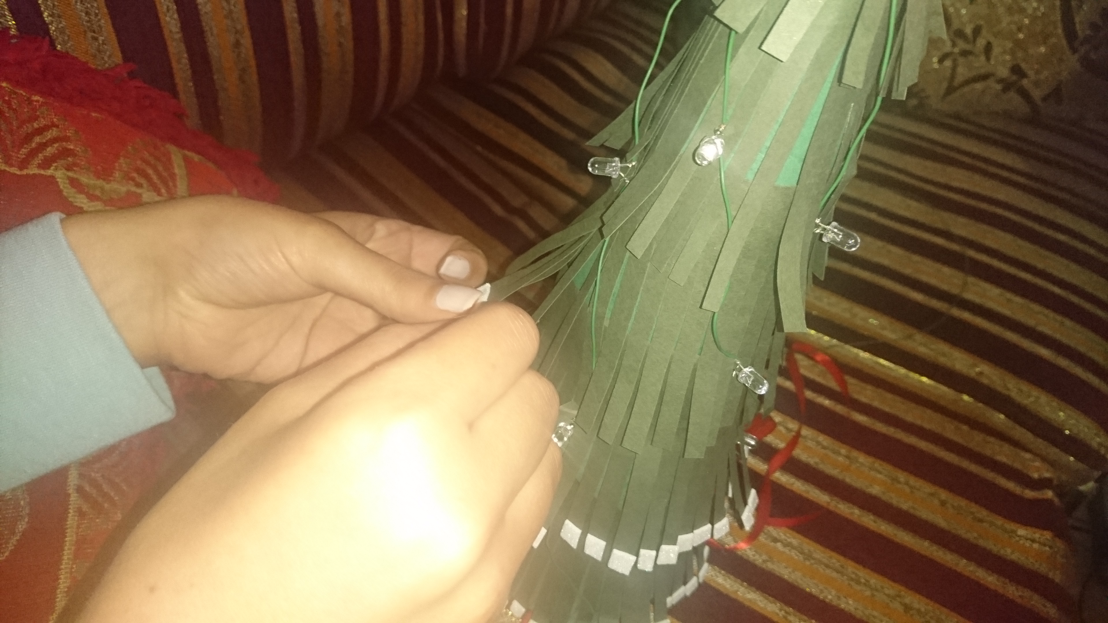
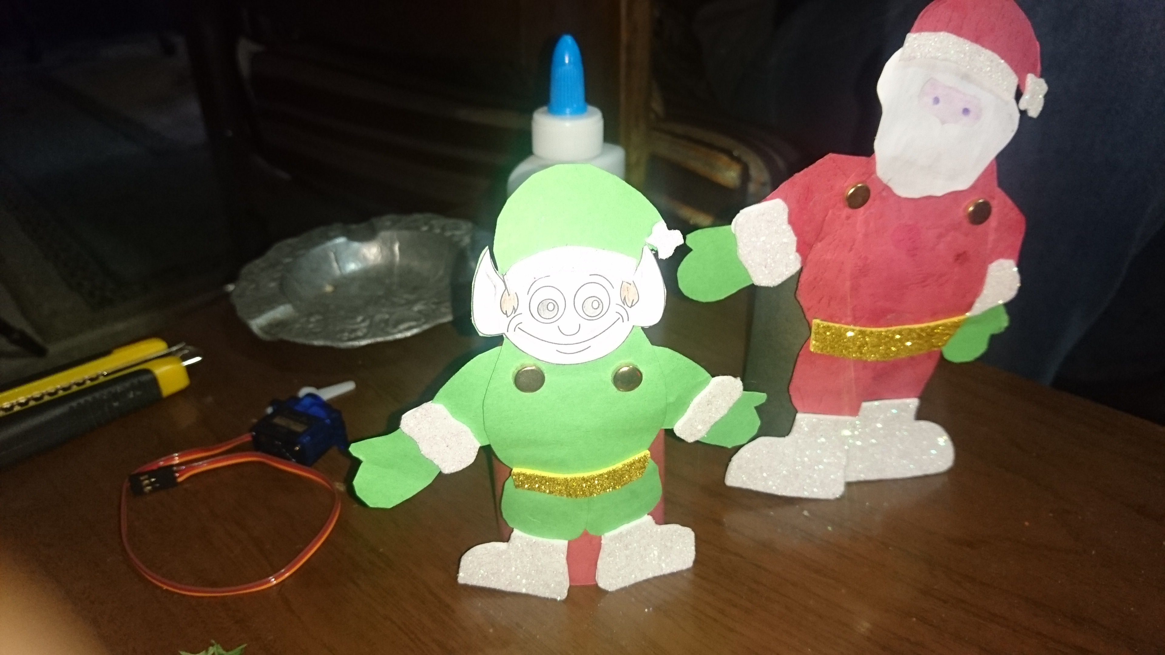
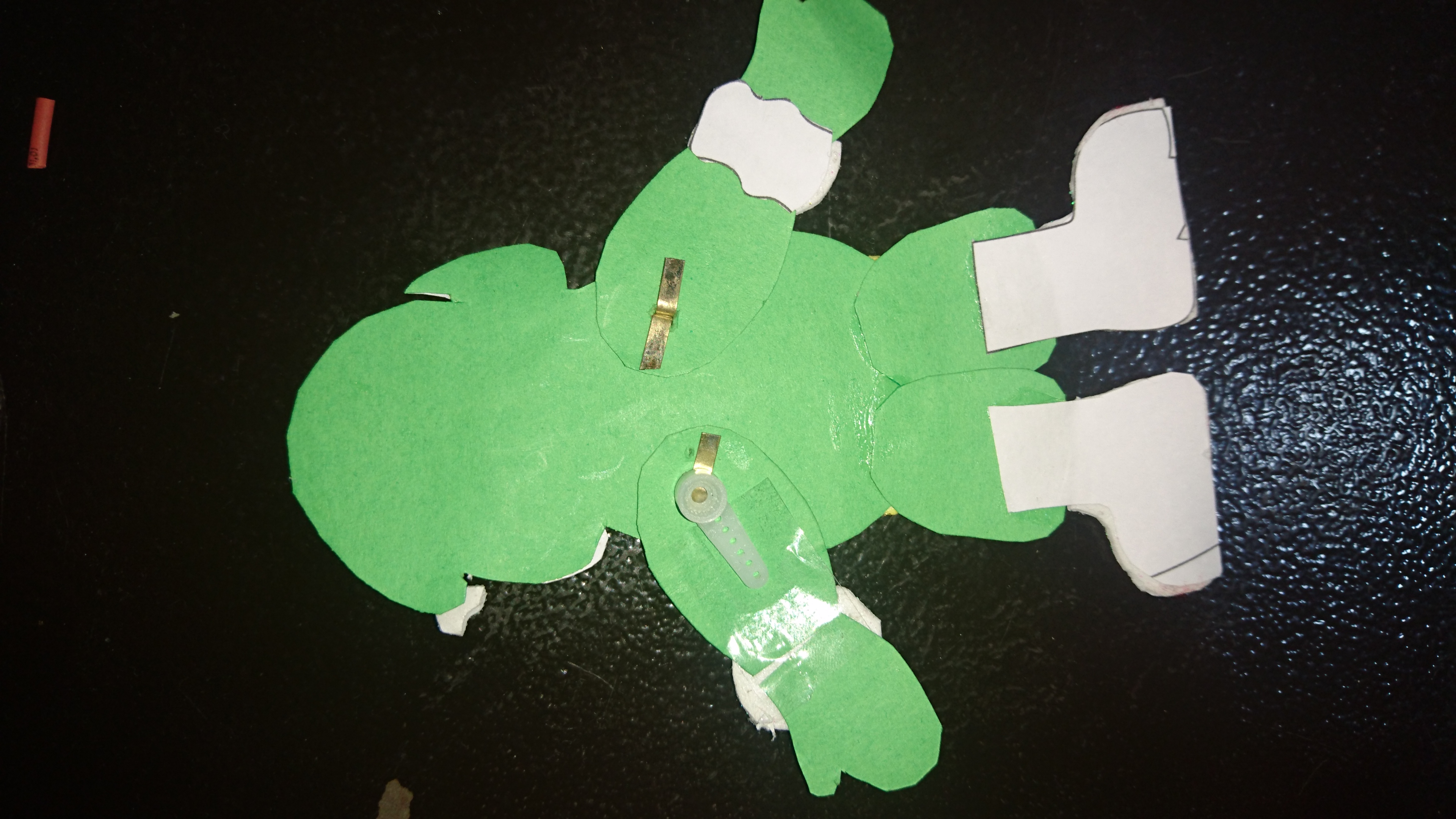
This project was made to be an interactive Christmas decoration, the tree LEDs, music played and the arms of Santa and Elf are all controlled using a phone app created using MIT App Inventor that communicates with the Arduino MKR1000.
Project Perspective
Mini Christmas IoT Show! is a sophisticated exploration of festive technology and IoT interaction. By focusing on the essential building blocks—the Bluetooth SPP (Serial Port Profile) sync and high-performance MIT-App-to-LED mapping logic—you'll learn how to communicate and synchronize your holiday tasks using a specialized software logic and robust high-performance setup.
Technical Implementation: Smartphone Interfaces and Light Sequences
The project reveals the hidden layers of simple sensing-to-show interaction:
- Identification layer: The MIT App Inventor Client acts as a high-resolution chronological eye, measuring every point of the user button-hits to coordinate the light-dispatch.
- Conversion layer: The system uses a high-speed digital protocol to receive high-speed data chunks for mission-critical sensing tasks.
- Acoustic Interface layer: A Passive Buzzer provides high-resolution visual and mechanical feedback for each musical status check (e.g., Jingle Bells).
- Communication Gateway layer: An HC-05 Bluetooth Module provides a manual control-override or autonomous status check during the initial calibration to coordinate status.
- Processing Logic: The Arduino code follows a "state-machine" (or light-dispatch) strategy: it interprets the Bluetooth characters and matches them to LED colors and buzzer pitches to provide safe and rhythmic Christmas cheer.
- Communication Dialogue Loop: Status bits are sent rhythmically to the Serial Monitor during the initial calibration to coordinate status.
Hardware-Holiday Infrastructure
- Arduino Uno: The "brain" of the project, managing the multi-directional serial sampling and coordinating the Bluetooth and LED sync.
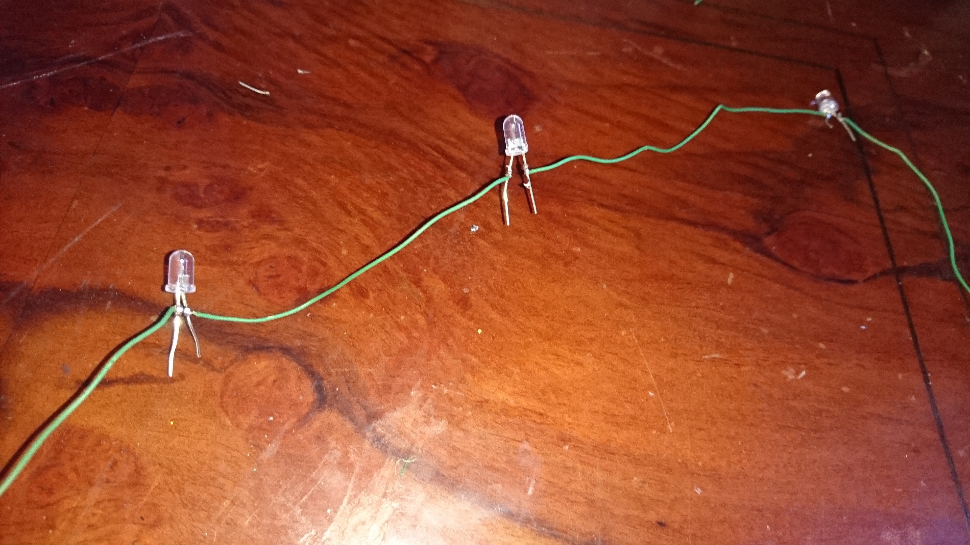
- Holiday LED String: Providing a clear and reliable "Visual Link" for each point of the tree decoration.
- HC-05 Module: Providing a high-capacity and reliable physical interface for your first successful "Festive Mission."
- Holiday Case: Essential for providing clear and energy-efficient protection for every point of the hardware.
- Buzzer Component: Essential for providing clear and energy-efficient sound for each point of your musical sensing.
- Micro-USB Cable: Used to program your Arduino and provides the primary interface for the system controller.
Show Automation and Interaction Step-by-Step
The festive light process is designed to be very efficient:
- Initialize Workspace: Correctly seat your LEDs and module inside your Christmas enclosure and connect them properly to the Arduino pins.
- Setup High-Speed Sync: In the MIT App UI, initialize the
Bluetooth.send()and define the scene IDs in thesetup()function. - Internal Dialogue Loop: The station constantly performs high-performance periodic serial checks and updates the show status in real-time based on your phone inputs.
- Visual and Data Feedback Integration: Watch your tree's dashboard automatically become a rhythmic status signal, pulsing and following your location settings in the room.
Steps to Make


Future Expansion
- OLED Identity Dashboard Integration: Add a small OLED display on the back to show "Current Song" or "Battery (%)."
- Multi-sensor Climate Sync Synchronization: Connect a specialized "Synchronized WiFi Module" to perform higher-precision "Multi-Tree Syncing" wirelessly via the cloud.
- Cloud Interface Registration Support Synchronization: Add a specialized web-dashboard on a smartphone over WiFi/BT to precisely track and log the total social history.
- Advanced Velocity Profile Customization Support: Add specialized "Machine Learning (vCore)" to the code to allow triggers to be changed automatically based on the user height!
Mini Christmas IoT Show is a perfect project for any science enthusiast looking for a more interactive and engaging holiday tool!
[!IMPORTANT] The Bluetooth Control requires an accurate Voltage Divider mapping (e.g., for the RX pin) in the code to avoid damaging the module; always ensure you have an appropriate Fail-Safe flag in the loop if the signal drops!