Hi.
This is a minimal drum kit using an Arduino UNO.
First of all, please check this instructables page.
https://blog.arduino.cc/2017/01/19/a-3d-printed-e-drum-pad/
Since I started making this, I was captivated by piezo and electronic drums.
I was fascinated by a very simple mechanism of electronic drums and the great invention called MIDI.
In other words, I could not be satisfied just by making pads.
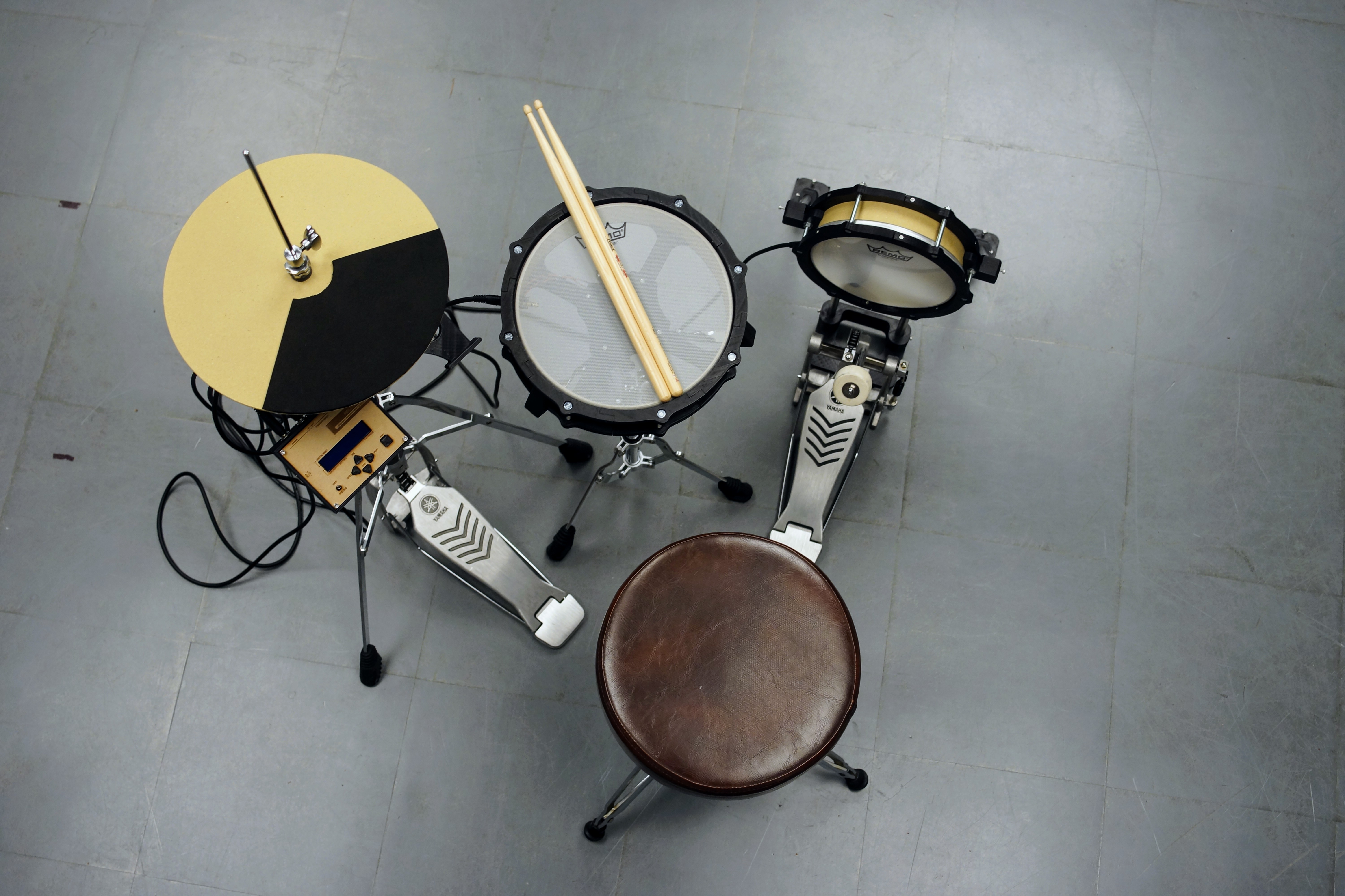
This drum kit is roughly divided into two productions.
1. Pad made with a 3D printer and thick paper.
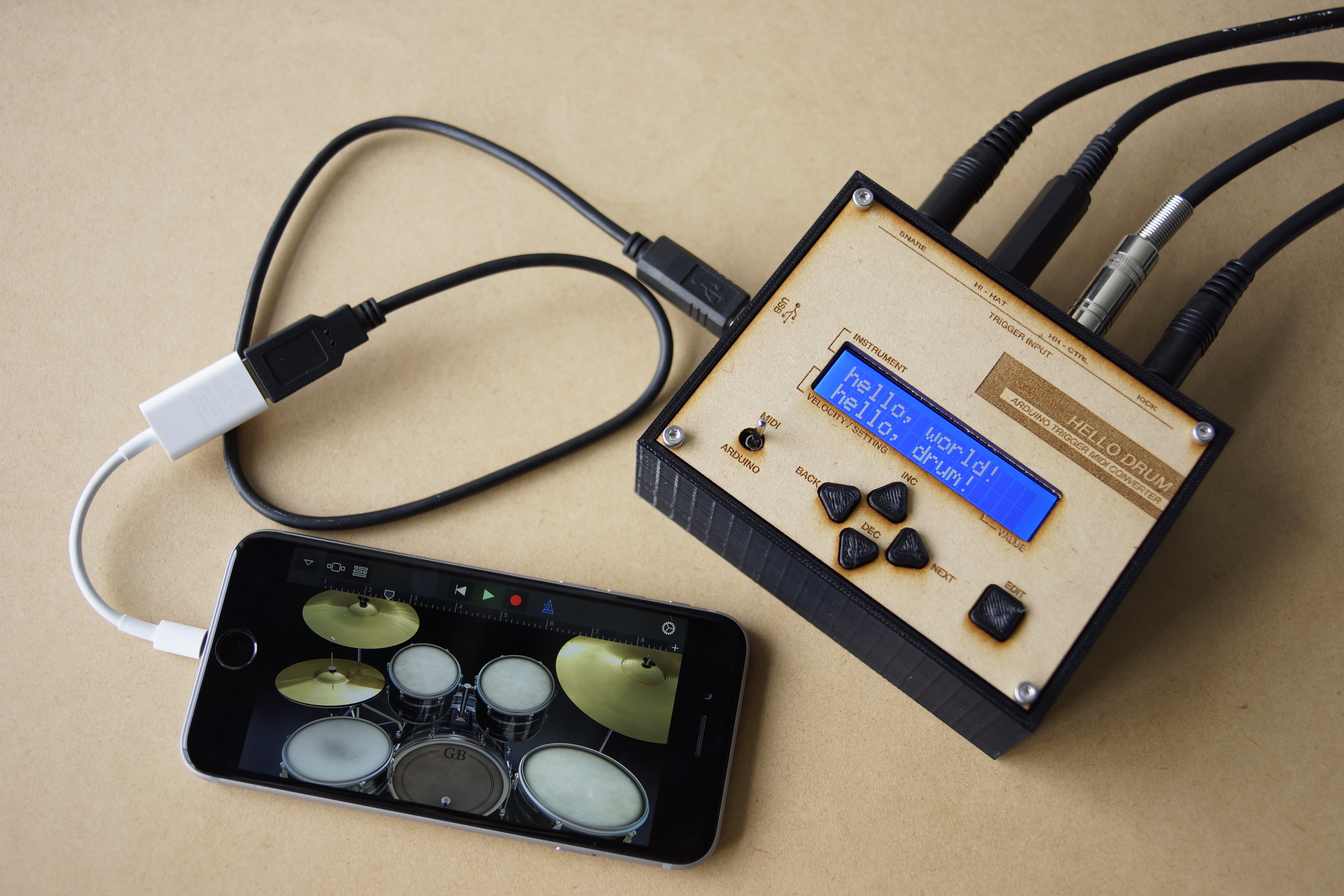
2. Trigger MIDI converter with Arduino UNO.
The signal sent from the pad of "1" is processed by the Arduino of "2" and converted into a MIDI signal. And the MIDI signal is transmitted from the Arduino to an iPhone, laptop, etc., and sound comes out.
You do not need to prepare a power supply other than a smartphone or PC.
Project Overview
"MIDI-Mechatronics" is a rigorous exploration into Percussive Signal Forensics and USB-MIDI Protocol Orchestration. By integrating 3D-printed structural mechanicals with high-sensitivity piezoelectric transducers, this project transforms physical kinetic energy into deterministic MIDI telemetry. The system features a custom DFU (Device Firmware Update) bootloader heuristic, allowing the Arduino Uno to be recognized as a native MIDI-class device without external bridging hardware. The build emphasizes high-fidelity "Trigger-to-MIDI" conversion, incorporating real-time calibration for threshold, sensitivity, and scanning-window harmonics.
What You'll Need
Tools
・3D Printer
・Laser Cutter (Extra)
・Hex wrench
・Cutter knife
・Circle cutter
・Soldering Iron
・Pipe Cutter
・Driver drill
・Drill bit 9mm / 10mm
Material
・1mm thick paper
・PLA filament
・Sponge Foam Sheets 5mm / 10mm
・MDF 2.5mm / 5.5mm (Extra)
・M6 - 70mm bolt and nuts
・M6 - 50mm bolt and nuts
・M3 - 10mm bolt and nuts
・M3 - 15mm bolt and nuts
・M3 - 25mm bolt and nuts
・M2 screw
・13 mm diameter Stainless steel pipe
Drum Hardware
・Mesh head 10 inch / 8 inch
・Snare stand (Anything is OK. I am using YAMAHA SS662.)
・Hi-hat stand (Anything is OK. I am using YAMAHA HS650A)
・Kick pedal (Anything is OK. I am using YAMAHA FP7210A)
・Drum stick
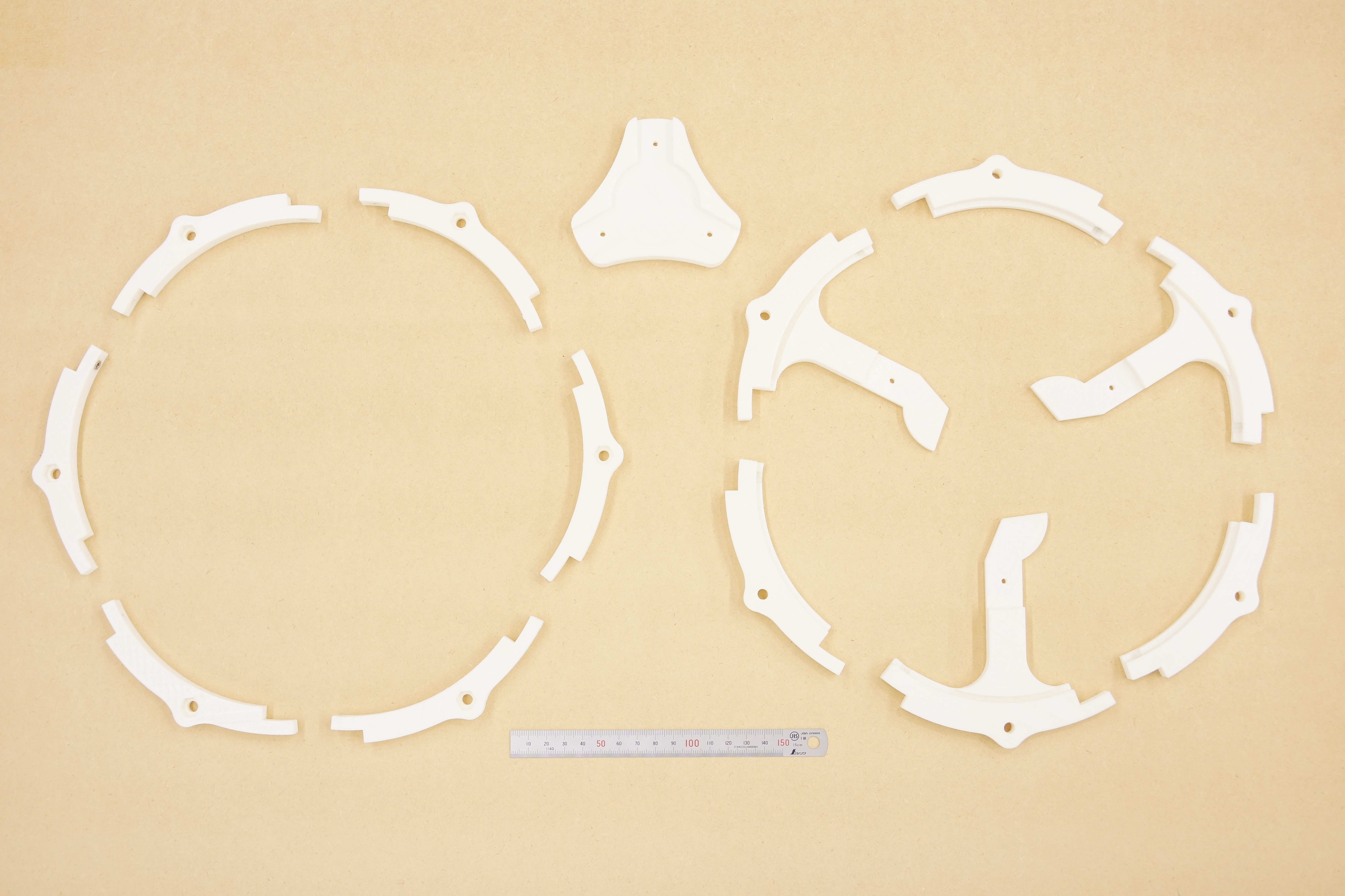
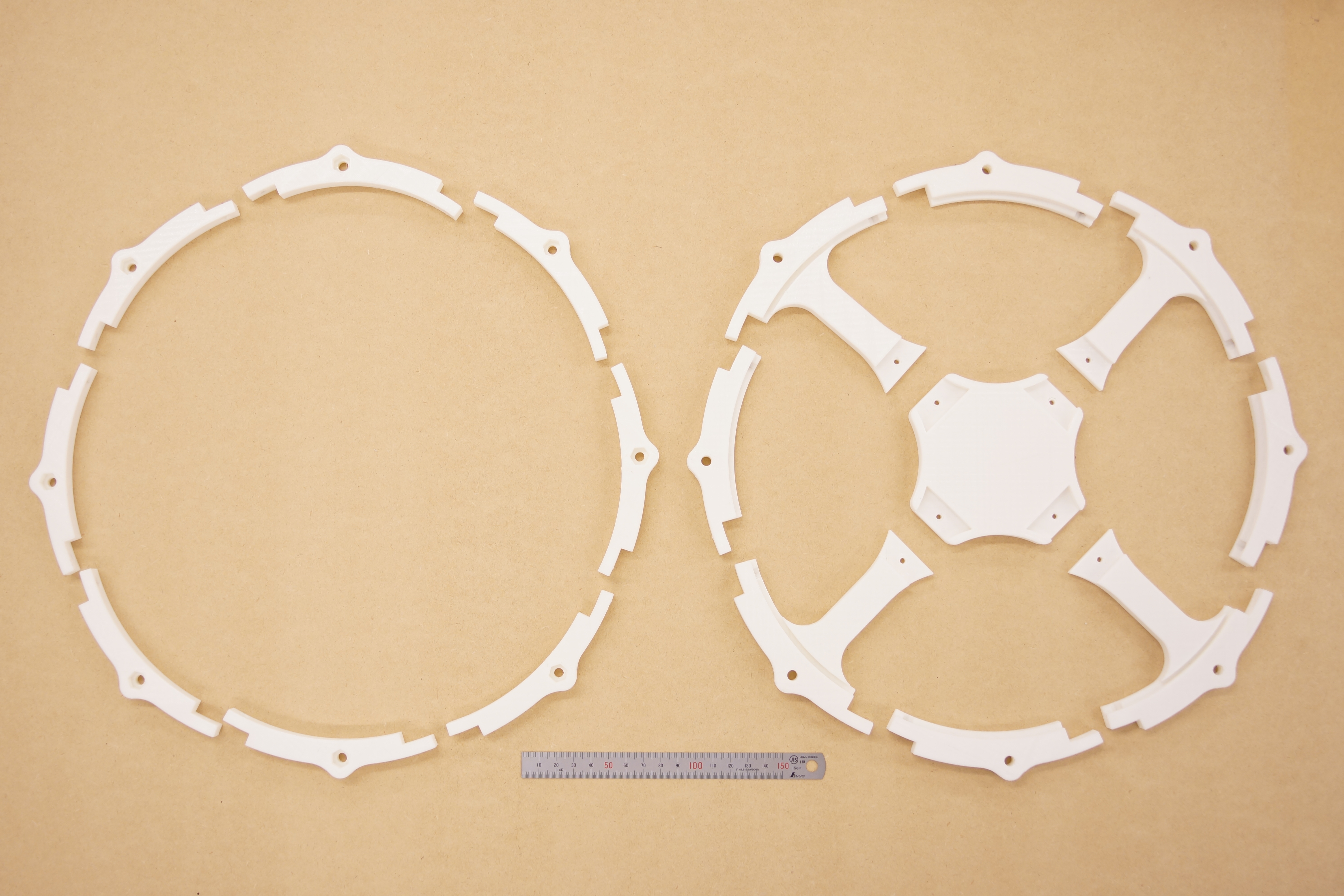
Step 1 : 3D Printing
All data is on Thingiverse and GitHub.
Please use Ver.2 for the rim.
I printed parts with infill at 20%. The thickness of the layer is 0.3 mm.
Also, you can use a laser cutter for making the pad.
https://github.com/RyoKosaka/drums/tree/master/vector
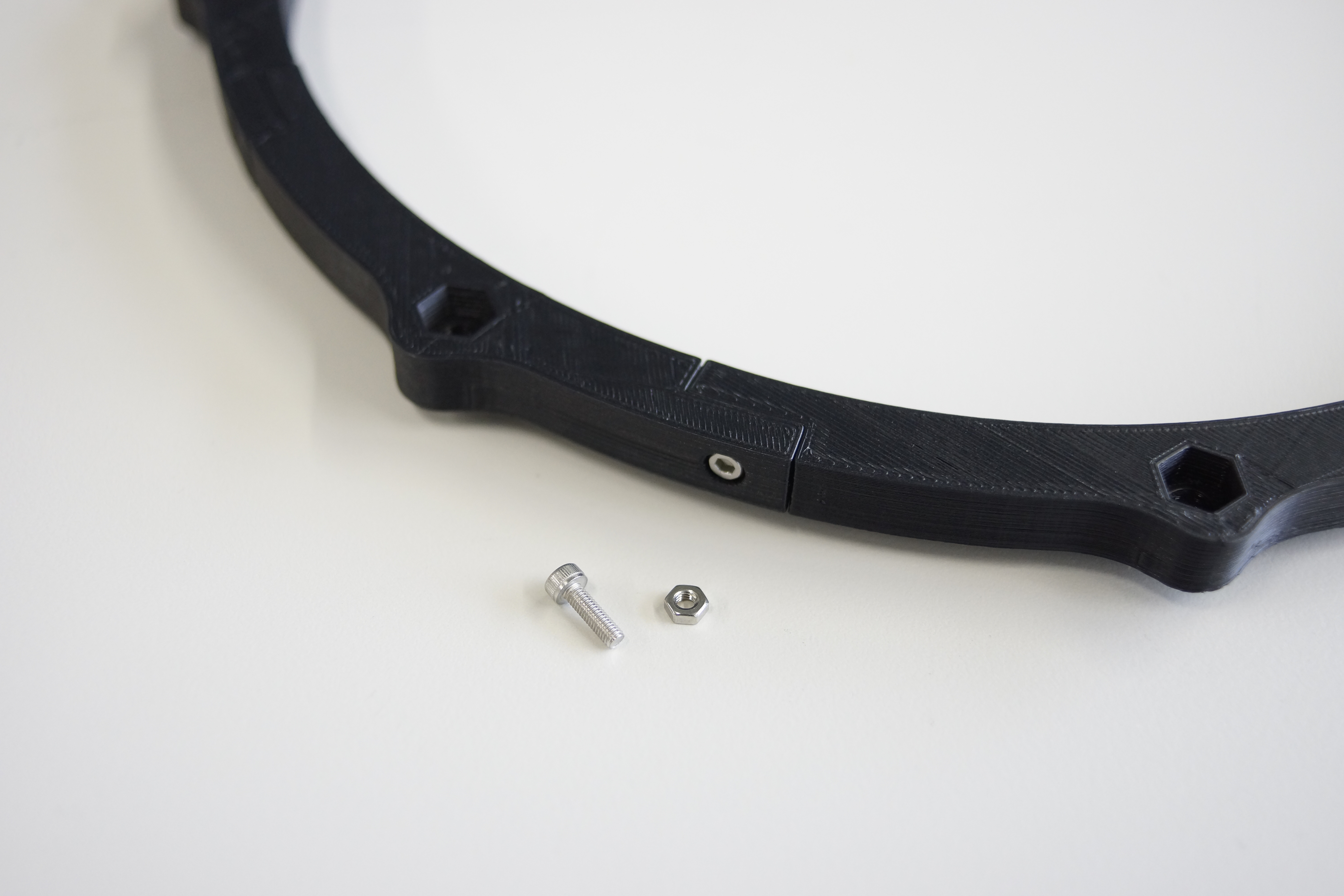
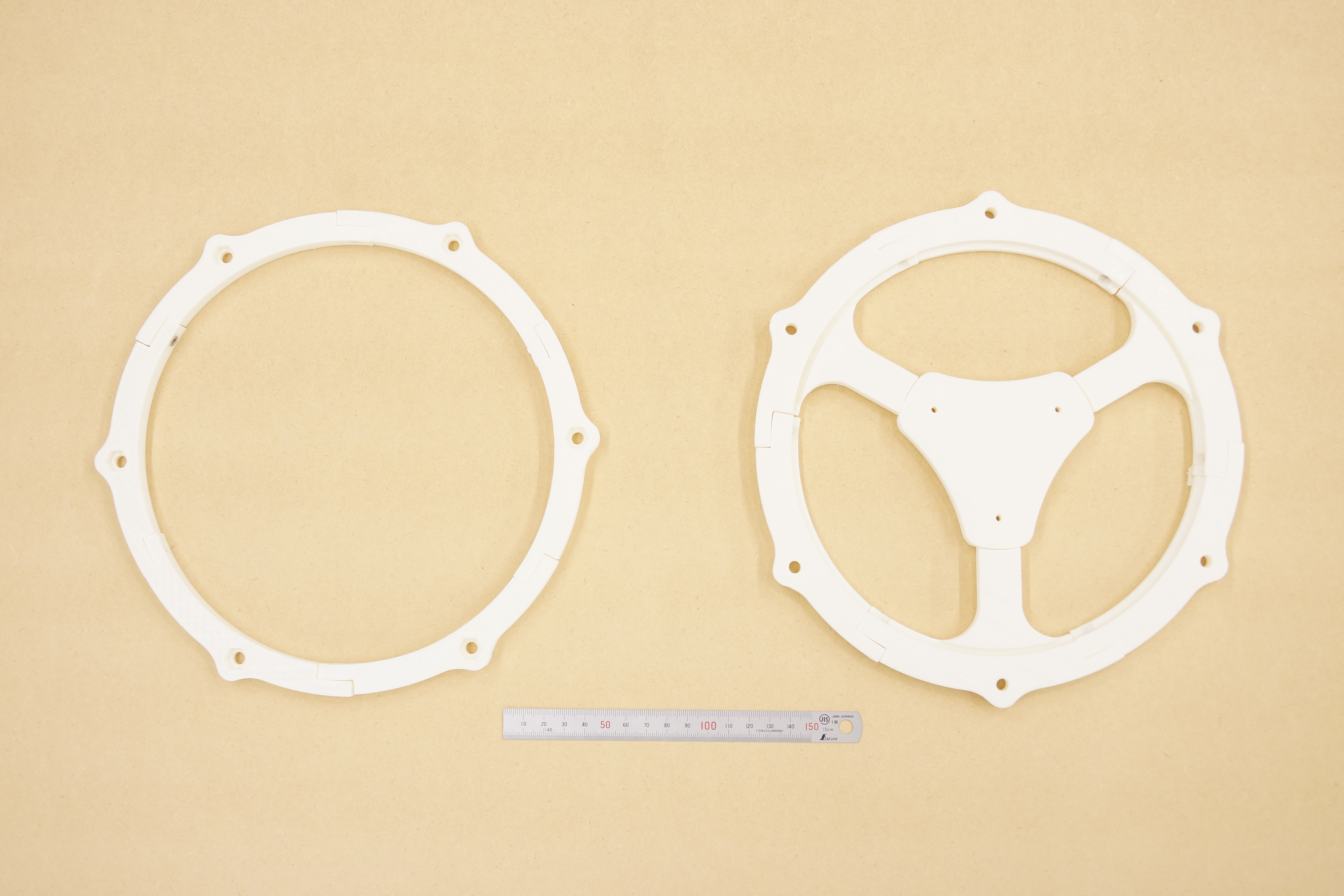
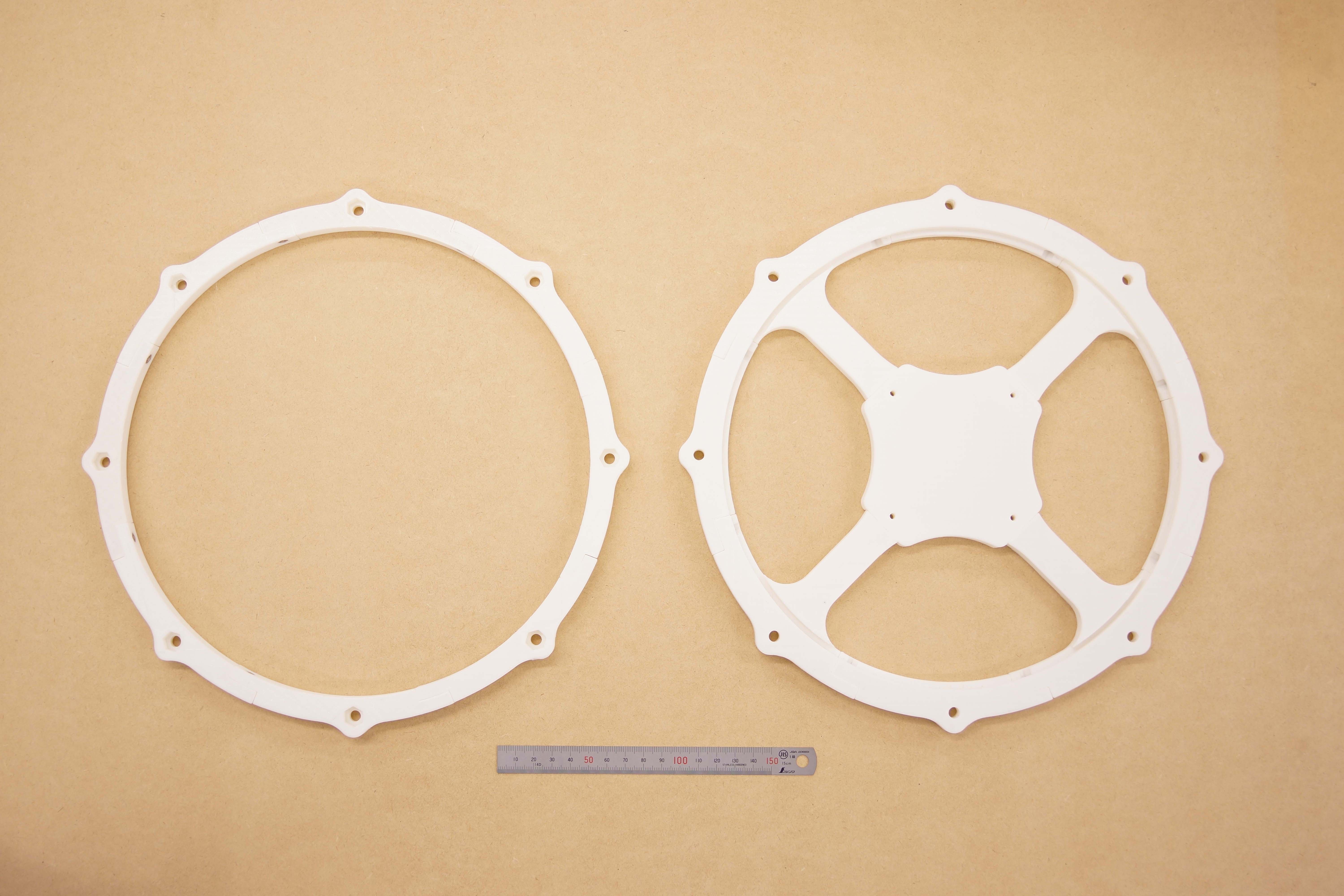
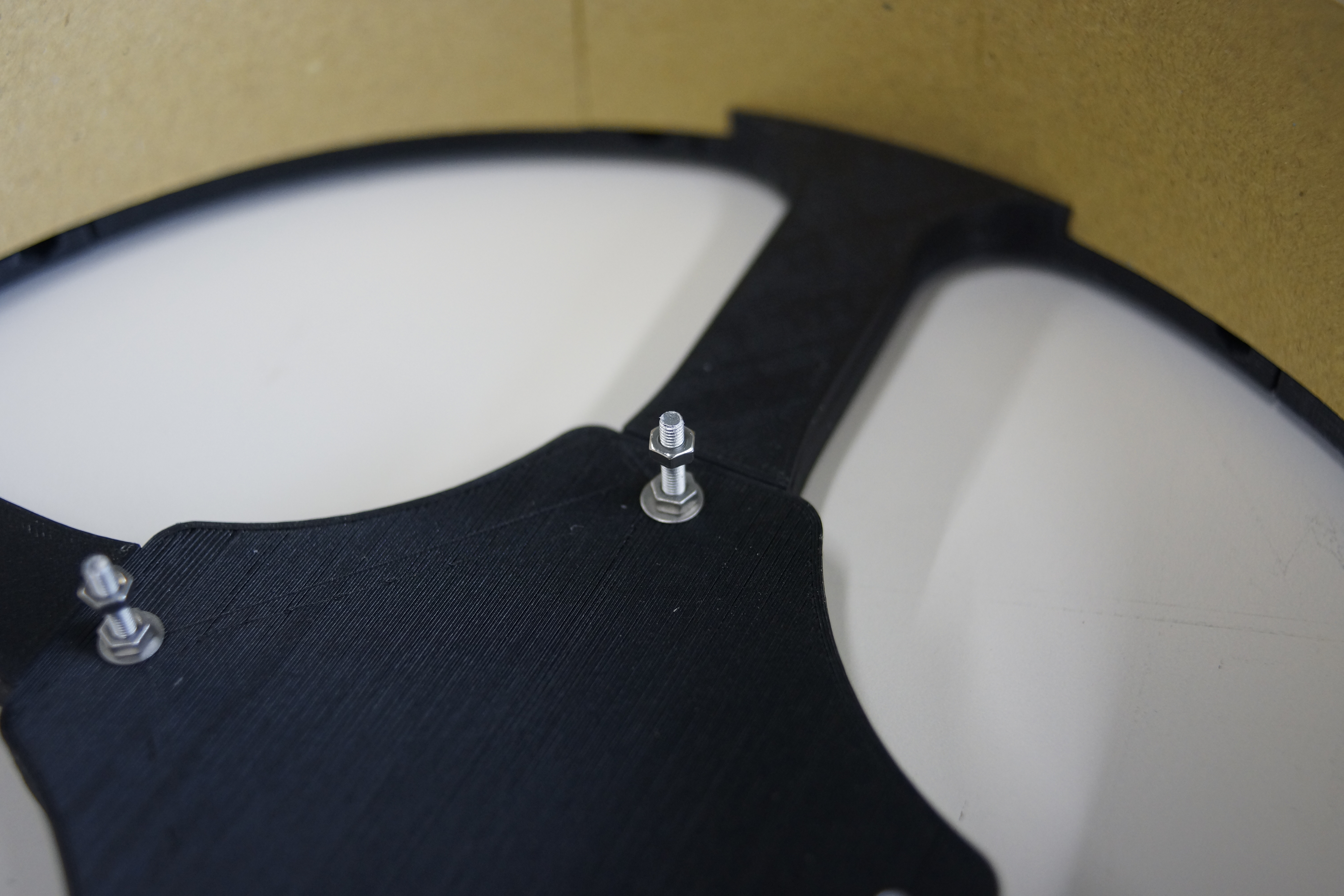
Step 2 : Assembling
Use M3-10mm bolts and nuts to connect the parts together.
Use the M3-15 mm or M3-25 mm bolts for the center part to fix the bottom part to each other.
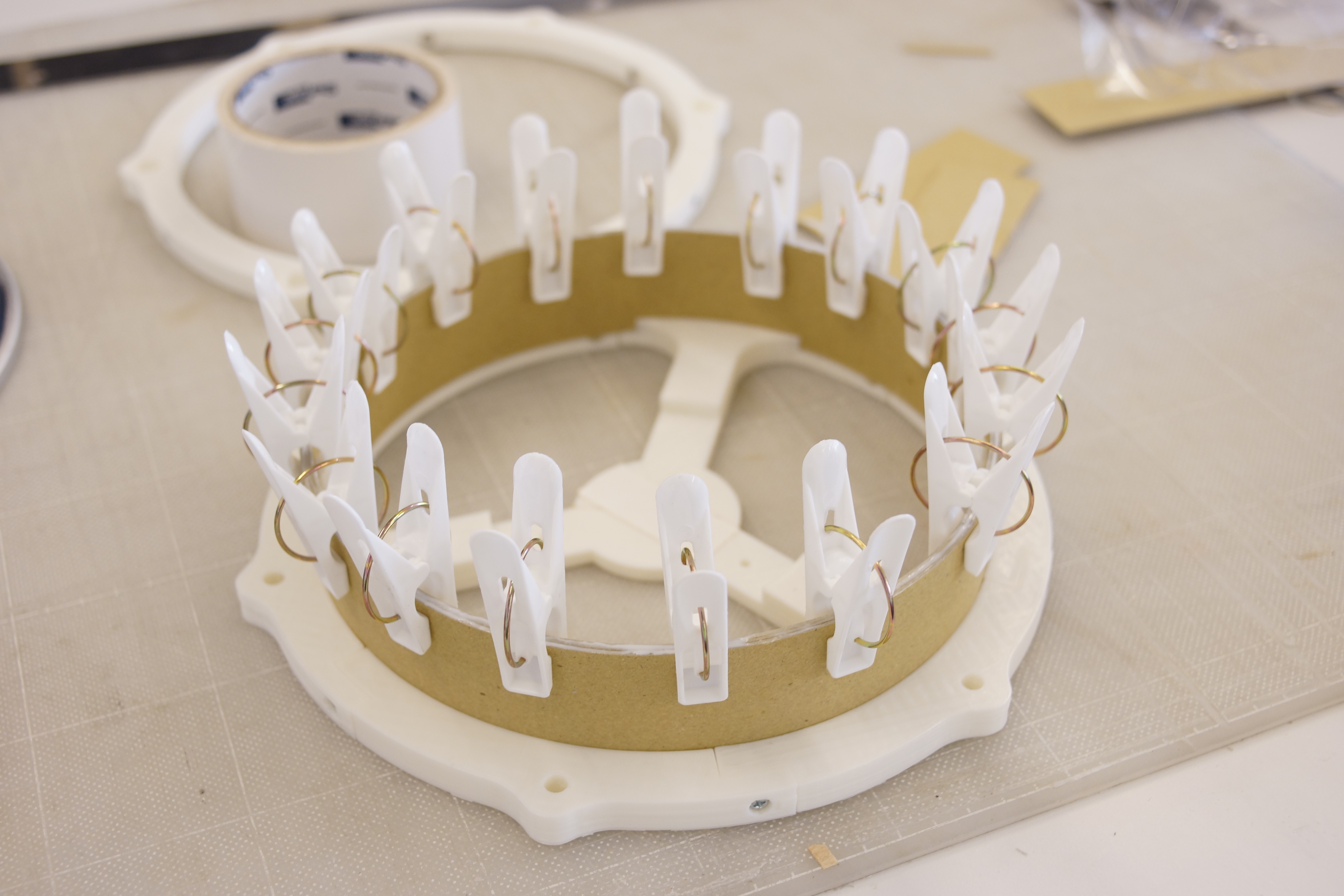
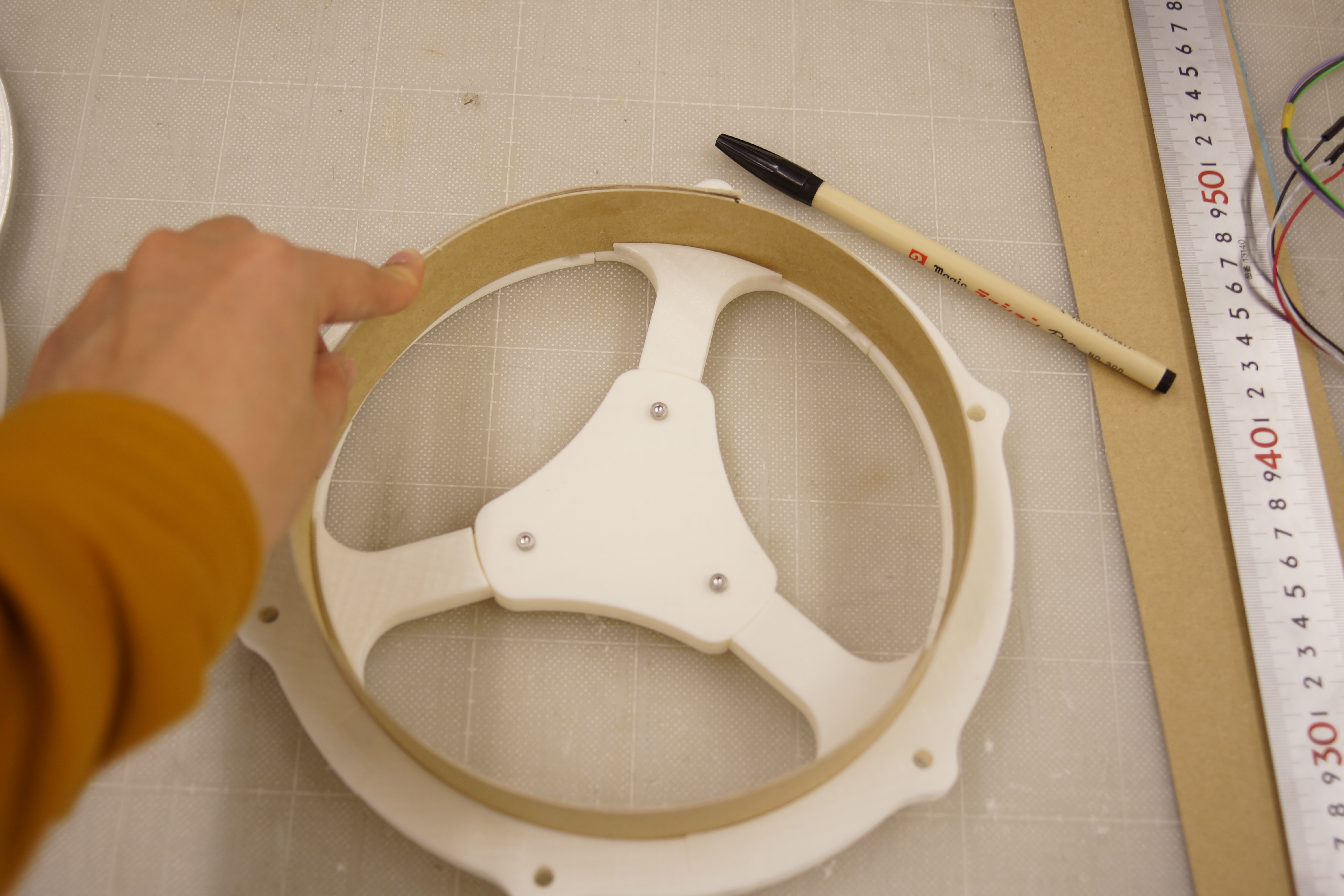
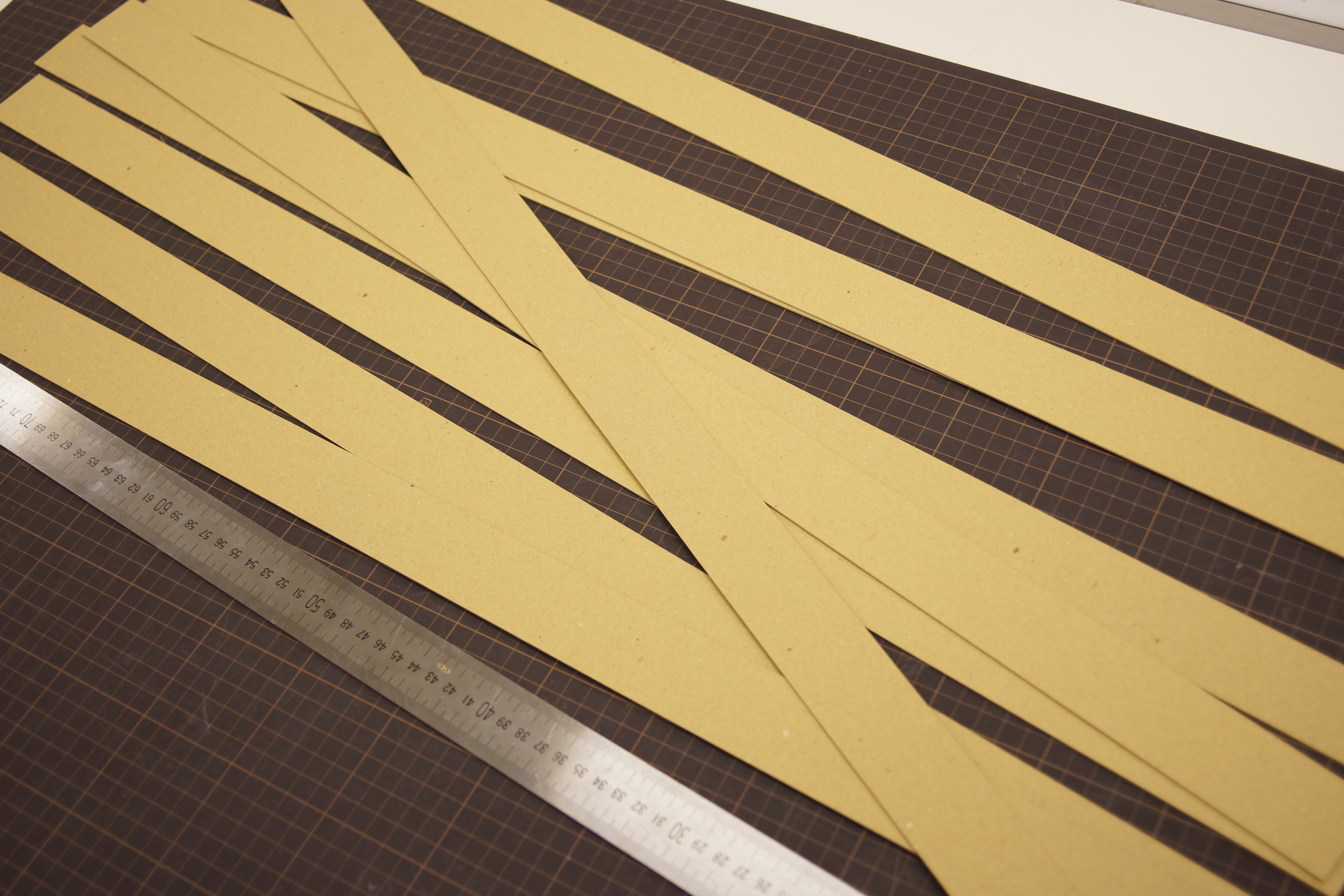
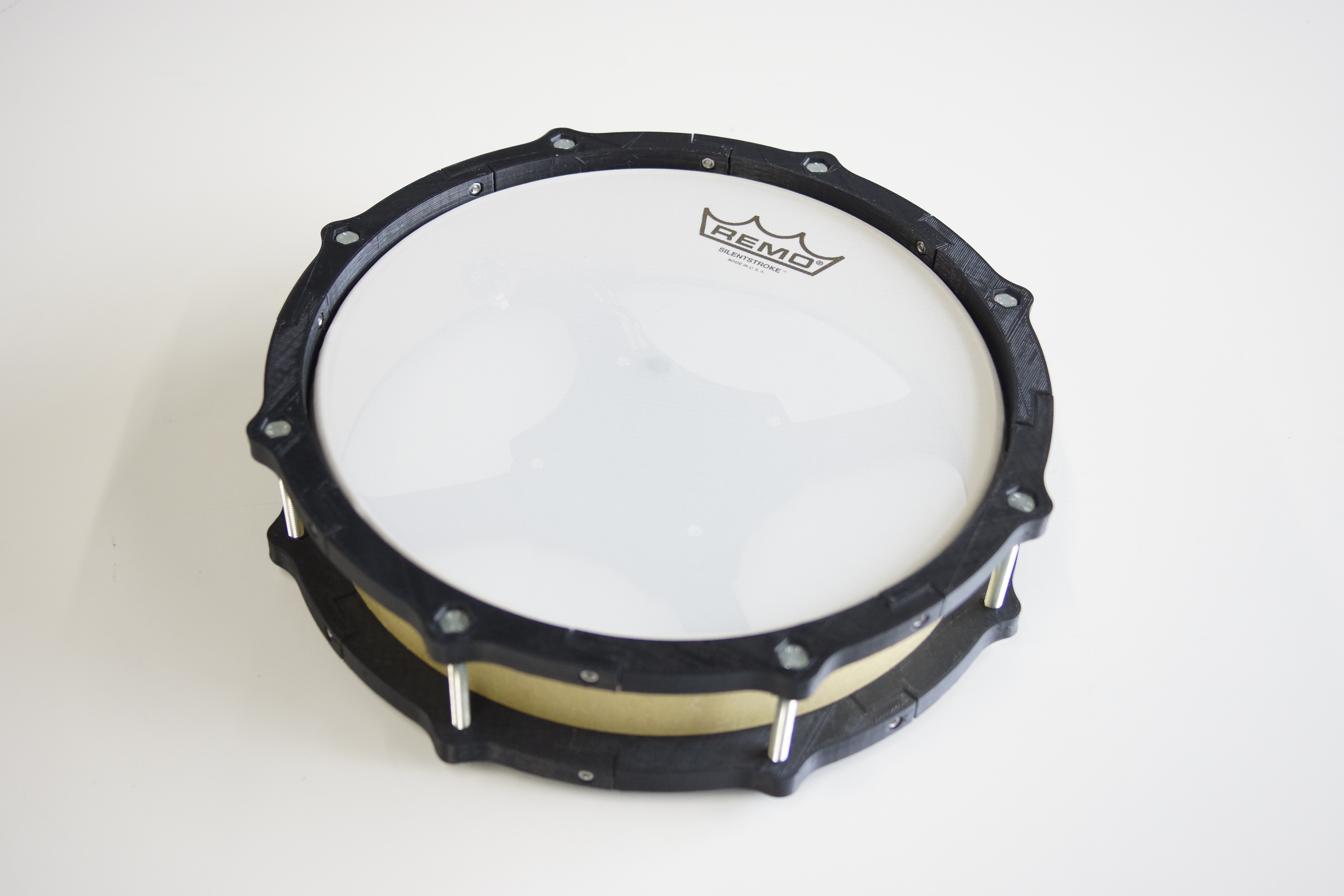
Step 3 : Making Shell
First, the height of the shell is 55 mm.
Please make three bands with a width of 55 mm.
The length is slightly longer than the length covering the pad.
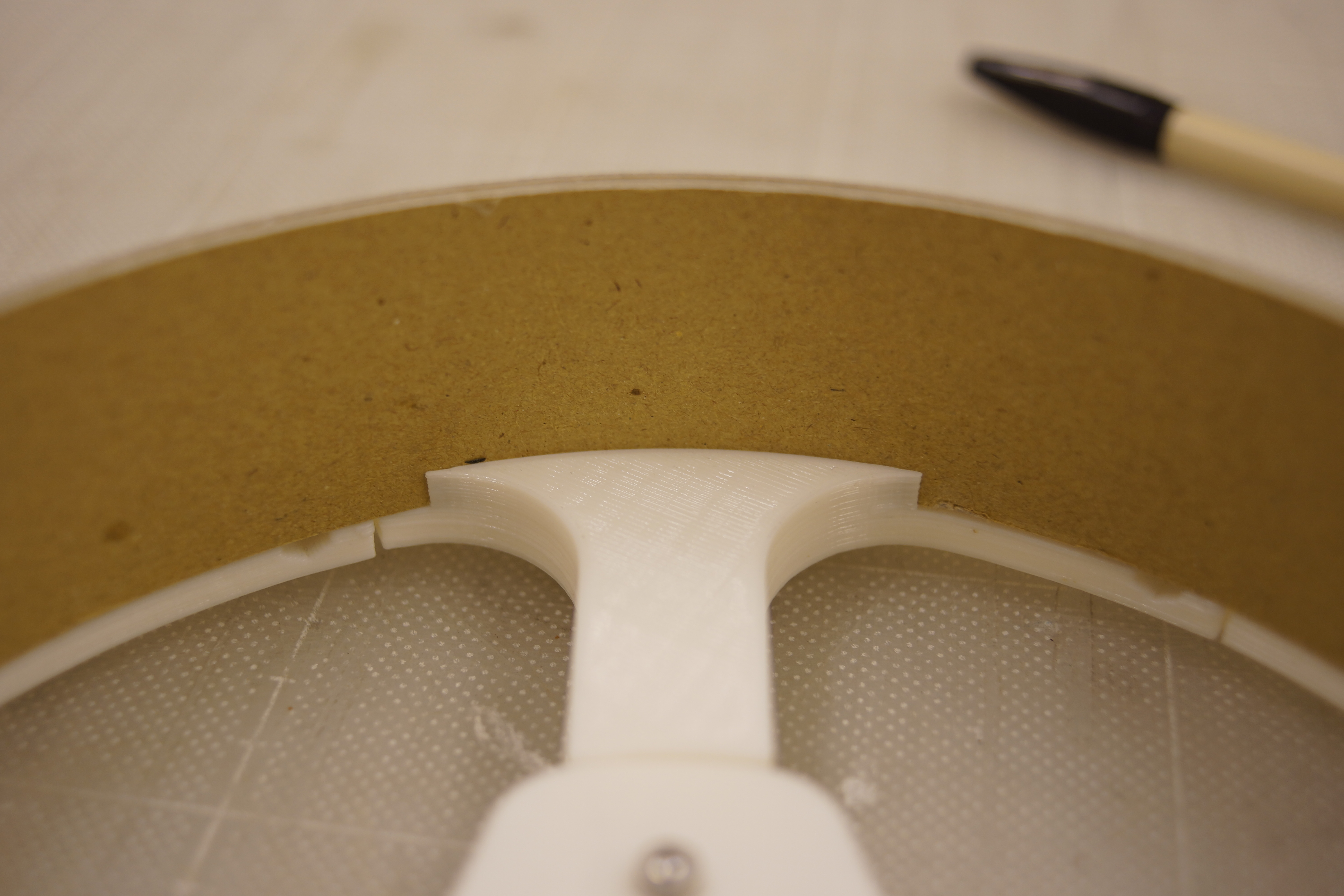
Since there is a gap at the bottom, try inserting one band into that gap.
Cut the band so that it will be perfect circle length.
Repeat this 3 times and overlay using adhesive.
When the shell dries, with the mesh head fixed, make a hole of 9 mm in diameter for the socket.
You can use butterfly nuts, but I also made tuning keys that can be tightened even with ordinary nuts, so please use it by all means.
For fixing the mesh head, use M6-70 mm bolts.
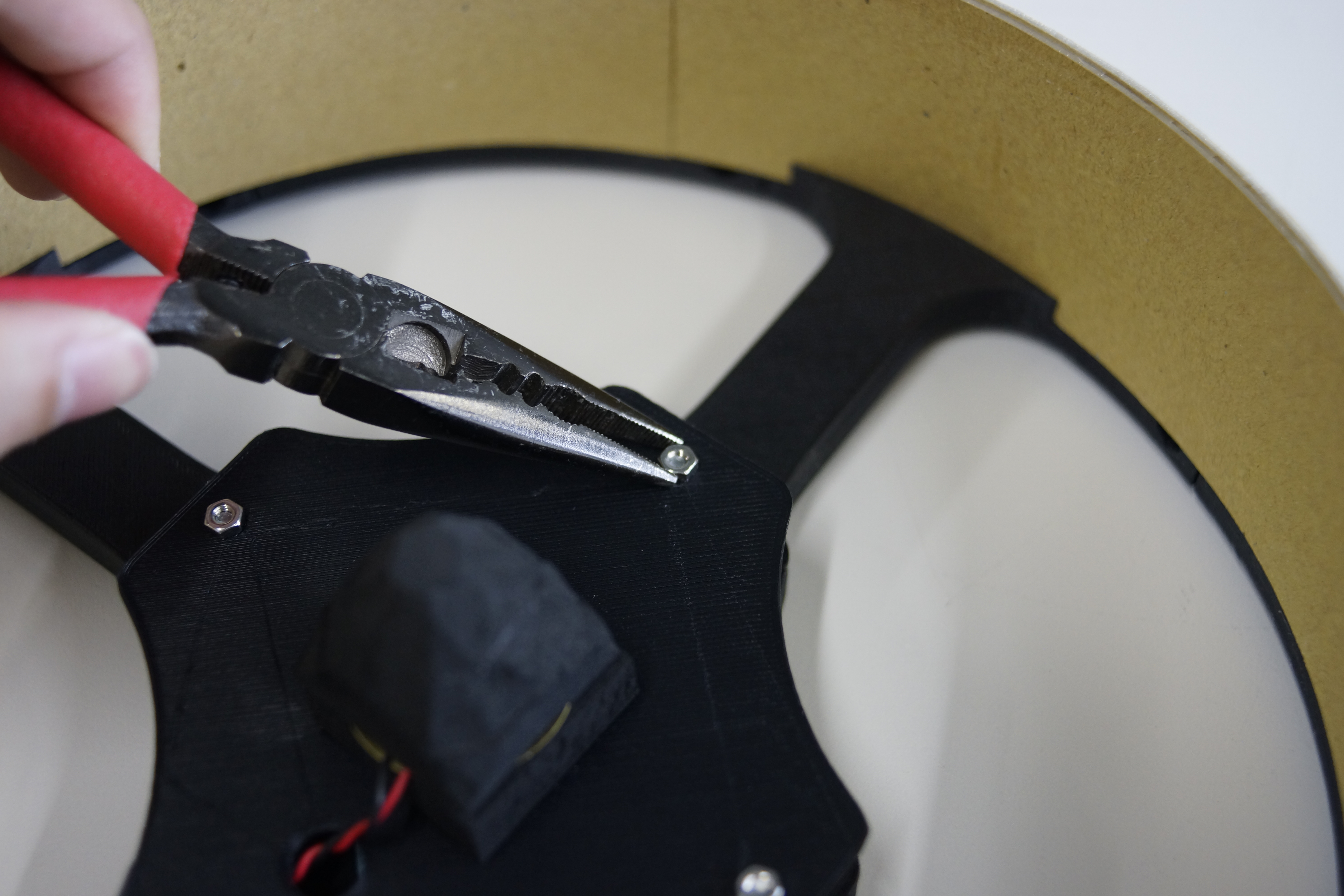
Once you've made a hole, remove the mesh head again to put a piezo
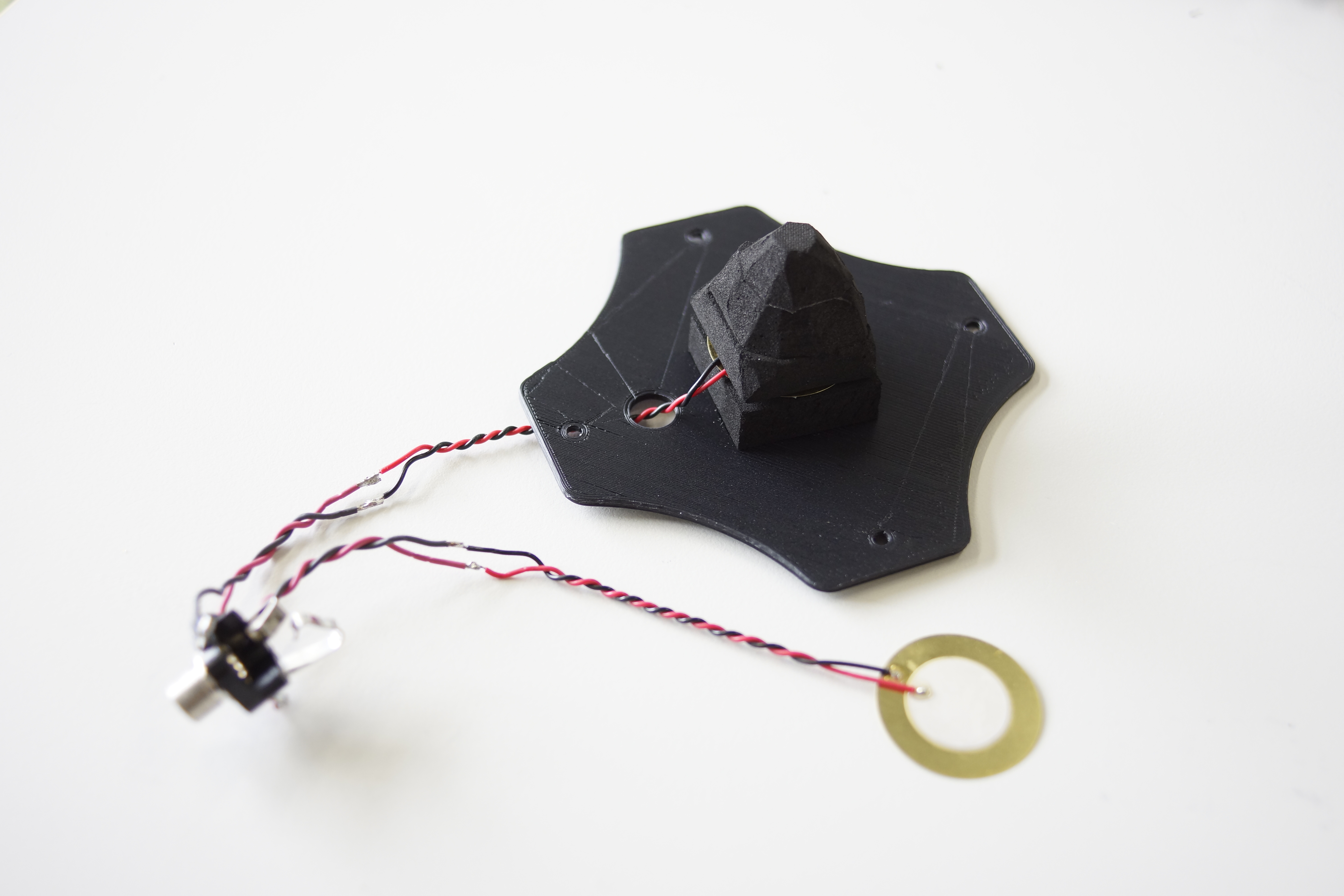
Step 4 : Attaching Piezo
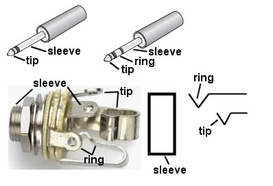
SNARE
In the case of a snare, use two piezos as shown in the picture.
Connect piezo's red cable to each of tip and ring.
Both black cables connect to sleeve.
Do not forget to thread the cables through the holes in the sensor plate when soldering.
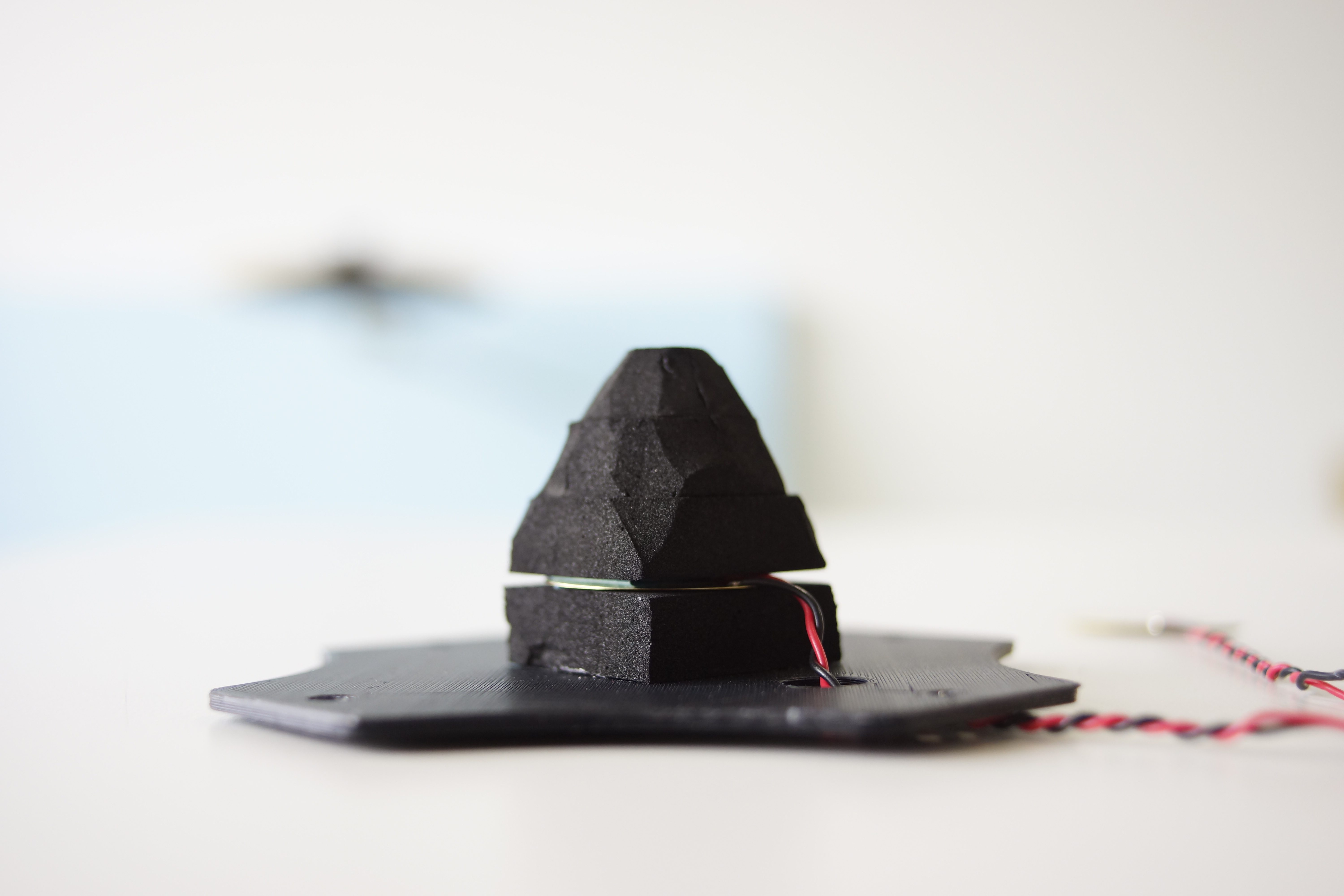
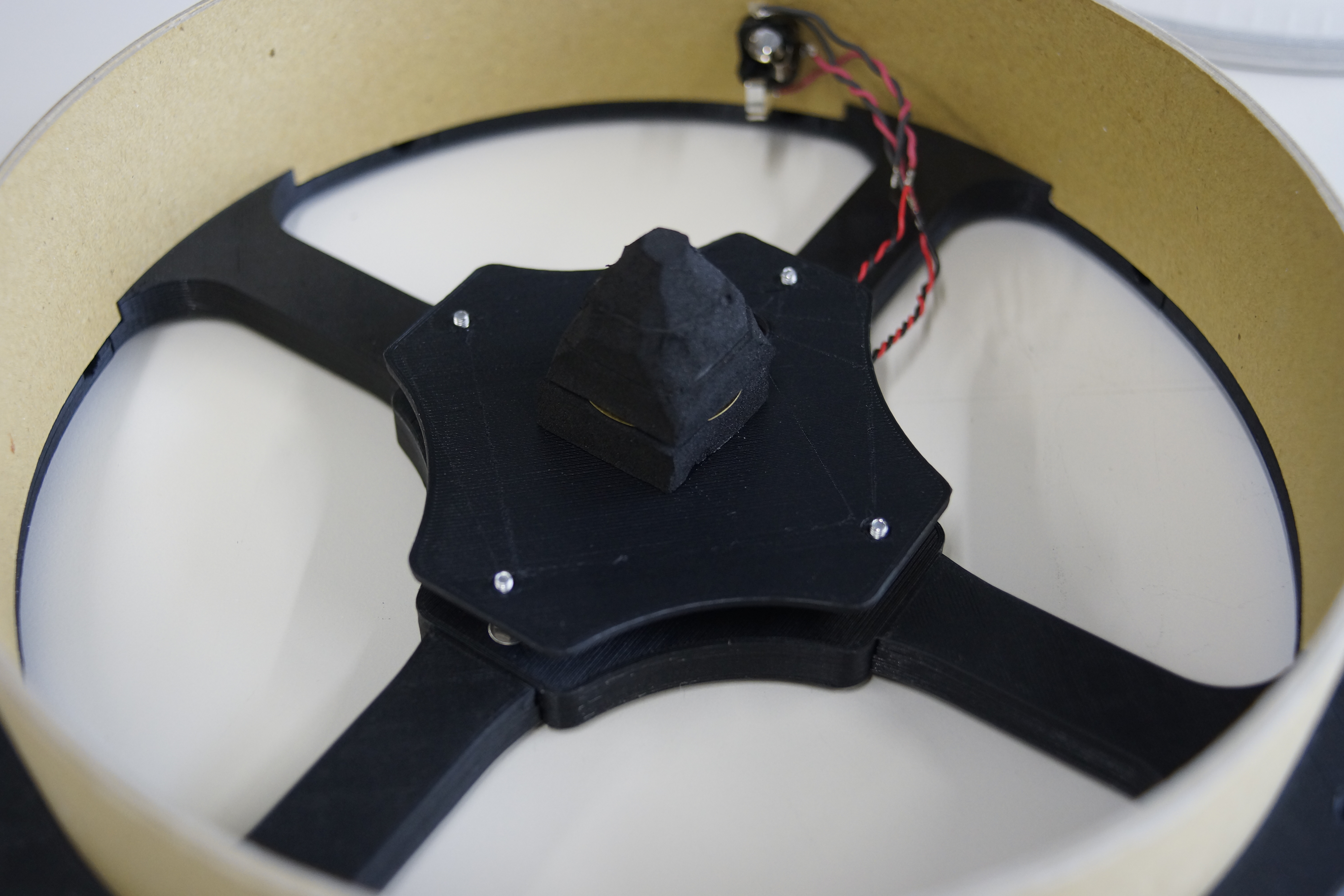
Piezo for the head (piezo connected to tip) needs to be sandwiched with 10 mm thick sponge foam as shown in the picture.
One below, three on the top. And make the top 3 cones like the picture.
Then put it on the sensor plate.
KICK
Since the kick pad uses only one piezo, only tip can be used.
No sensor plate is required. Two sponge foams under the piezo
Place the sensor offset from the center.
It is because Arduino can not judge the strength of hit if beater hits sensor directly.
HI-HAT
The circuit is the same as the kick pad.
Put a piece of 10 mm thick sponge foam under the piezo.
Piezo is delicate. Be careful not to bend or hurt.
Technical Deep-Dive
- Piezoelectric Vibrational Forensics:
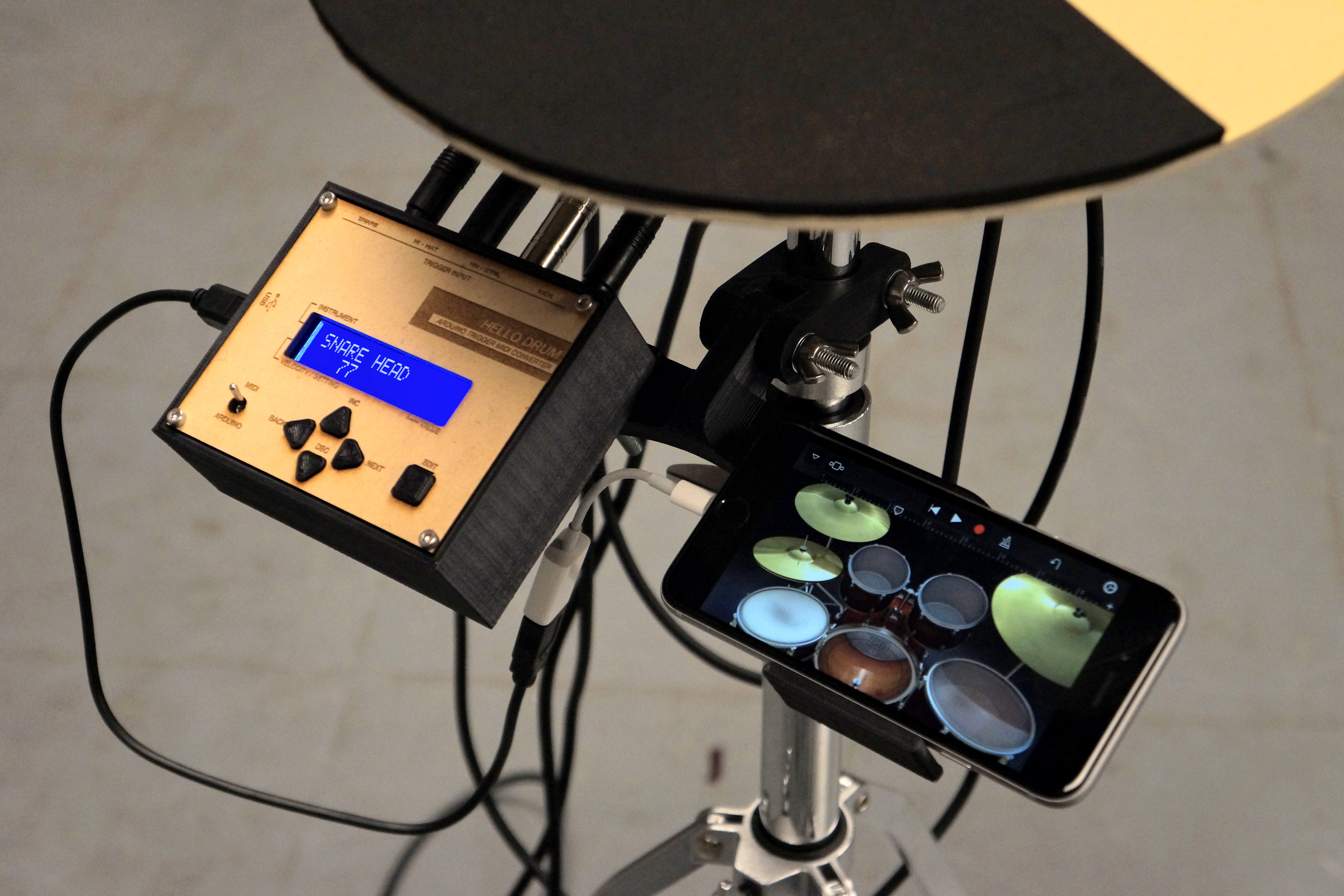
- The ADC Peak-Detection Diagnostics: When a drum-pad is struck, the piezo element generates a high-voltage transient $(V_{peak} > 50\text{V})$. The forensics involves a Vibrational Scanning-Window, where the Arduino samples the analog pin for several milliseconds $(\text{Scan Time})$ to capture the absolute peak magnitude. This magnitude is then linearly mapped to a $7$-bit MIDI Velocity value $(0-127)$, ensuring that the acoustic volume in the DAW correlates with the physical impact-force forensics.
- Signal Integrity & Protection Heuristics: To prevent ADC destruction from high-voltage overspikes, the circuit utilizes a $5.1\text{V}$ Zener diode as a hard-clipping diagnostic node. A $1\text{M}\Omega$ resistor provides the necessary impedance-decay forensics to ensure the signal returns to baseline rapidly enough for high-speed double-stroke detection.
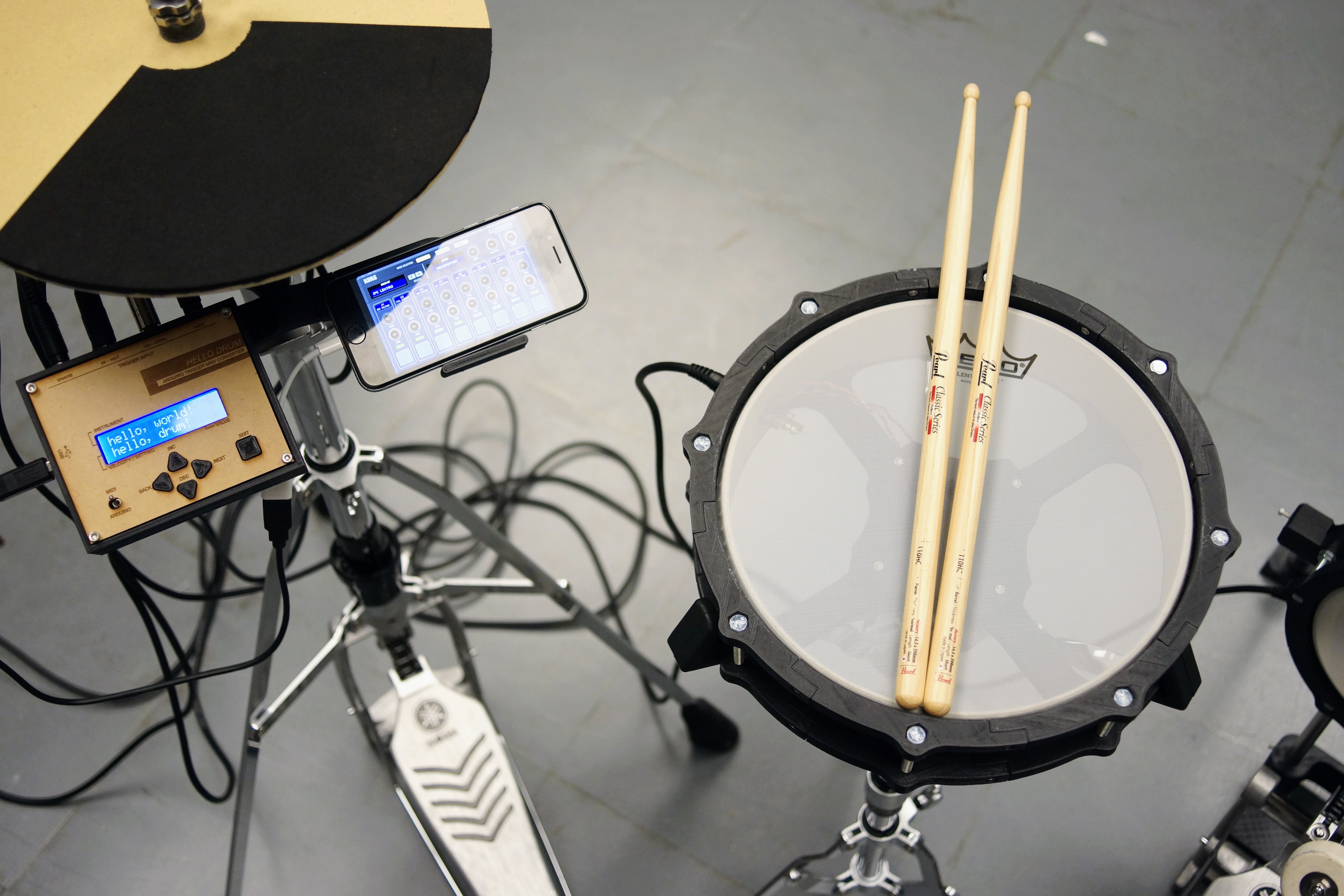
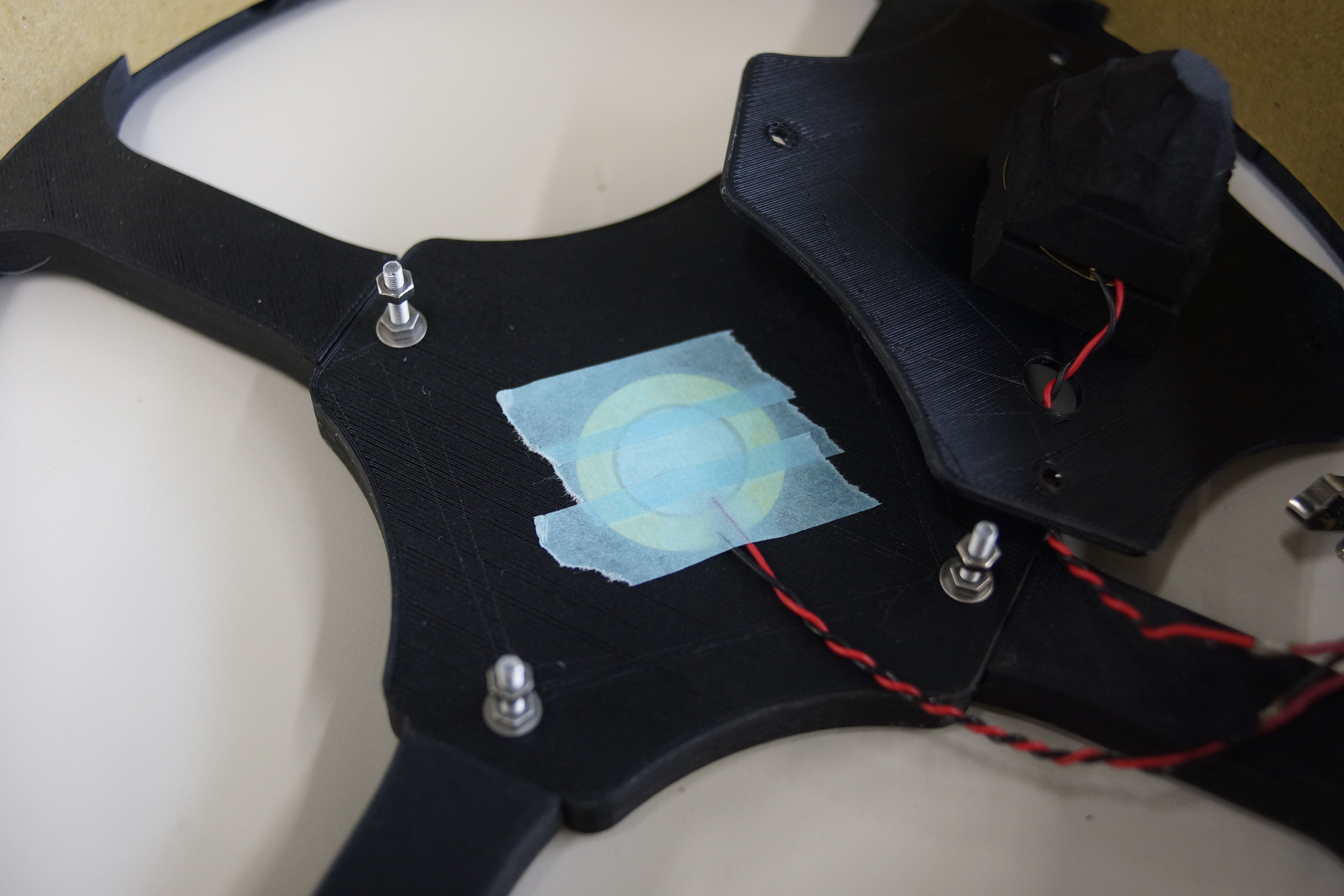
Step 5 : 10 inch Snare Pad
First attach the sensor for the rim.
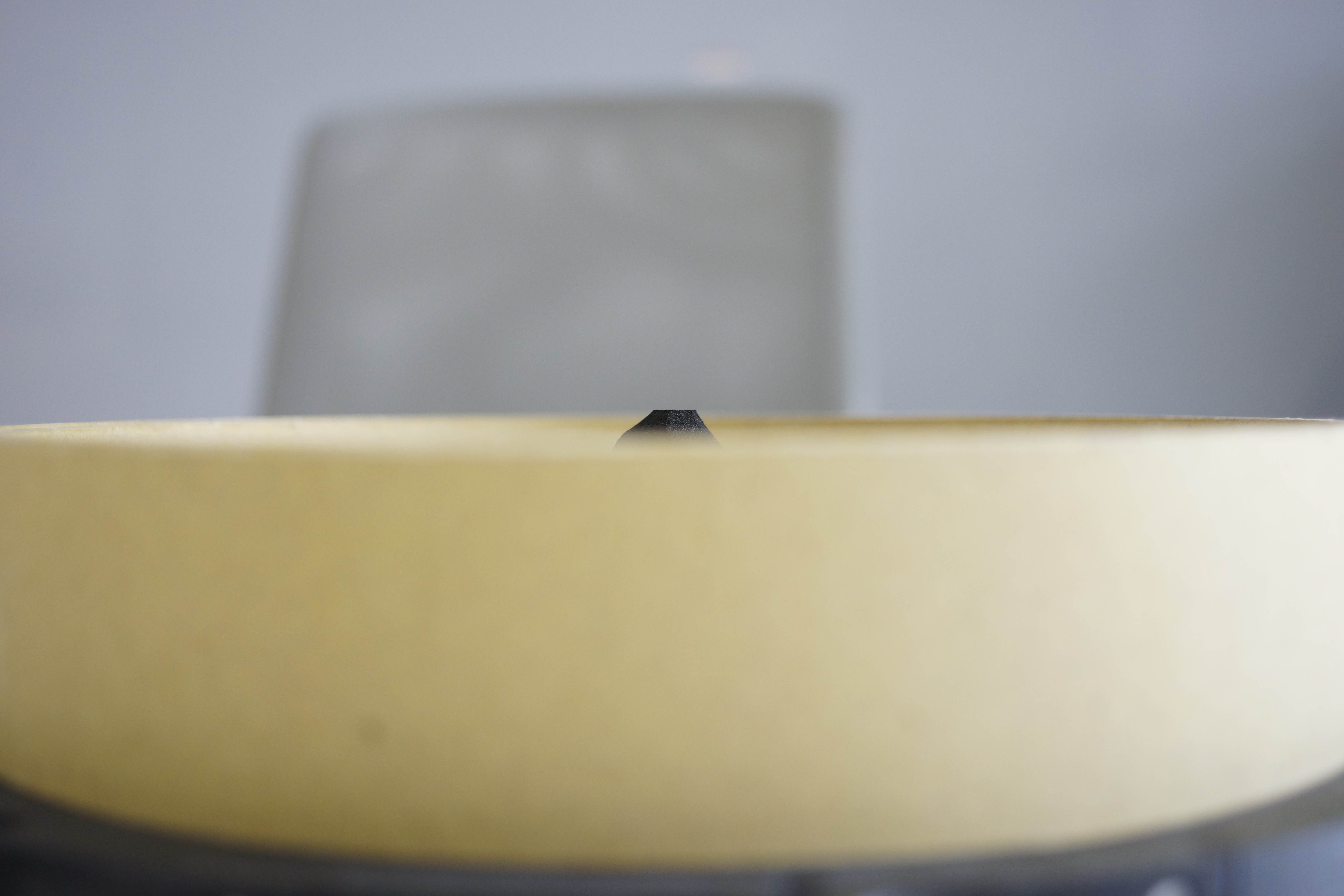
Fix the sensor plate. Firmly fix it. Make the end of the cone visible 2-3 mm when viewed from the side.
Of course, the same procedure is also used when using an 8-inch pad as a snare.
Step 6 : 8 inch Kick PAD
First, cut a 13 mm diameter stainless steel pipe.
Make two 200 mm and two 365 mm.
Since the length can be adjusted, even if there is some error in the length, it is OK.
Assemble them with reference to pictures.
In order to fix the pipe, it is designed so that the M3 nut can be loaded inside the part.
Fix the pipe securely. Use M3-15 mm bolts and nuts.
ข้อมูล Frontmatter ดั้งเดิม
apps:
  - "Arduino IDE"
  - "MocoLUFA (MIDI Bootloader Firmware)"
  - "GarageBand / DAW (Photonic Audio Engine)"
author: "ryokosaka"
category: "Audio & Sound"
components:
  - "1x Laser cutter (generic)"
  - "1x 3D Printer (generic)"
  - "1x Zener Diode - 5.1V 1W"
  - "1x circle cutter"
  - "1x Resistor 1M ohm"
  - "1x USB-A to B Cable"
  - "1x Resistor 10k ohm"
  - "1x Standard LCD - 16x2 White on Blue"
  - "1x Arduino UNO"
  - "1x Force Sensitive Resistor (FSR)"
  - "1x Piezo"
  - "1x Lightning to USB Camera Adapter"
  - "1x Soldering iron (generic)"
  - "1x Pushbutton switch 12mm"
  - "1x Slide Switch"
  - "1x TRS Socket"
description: "A professional-grade electronic percussion node featuring high-velocity MIDI-protocol diagnostics, piezoelectric vibrational forensics, and custom DFU-bootloader heuristics."
difficulty: "Intermediate"
documentationLinks: []
downloadableFiles:
  - "https://projects.arduinocontent.cc/70828970-4418-44b8-a4cb-5de28422d544.ino"
  - "https://create.arduino.cc/editor/ryokosaka/076e0136-daf4-4d9e-b807-335a5cd0dc8f"
  - "https://projects.arduinocontent.cc/70828970-4418-44b8-a4cb-5de28422d544.ino"
encryptedPayload: "U2FsdGVkX18sToHT/bn1O/0oIw4MgNTgdvKpRiDNqN9KWh21v/QChdBDXRoyjiyBVIEMcGddN3meQmmFR6jaNFgTFfAIoS1BKApJ7/1exXI="
heroImage: "https://cdn.jsdelivr.net/gh/bigboxthailand/arduino-assets@main/images/projects/minimal-midi-drum-kit-with-3d-printer-61e044_cover.JPG"
lang: "en"
likes: 41
passwordHash: "c39b7556c3be3282c89bb124f2f4d89dd9da7dd7c033bd9da3c9ae5a2d0db511"
price: 2450
seoDescription: "Build a Minimal MIDI Drum Kit using Arduino UNO and 3D Printer. A simple DIY project for music lovers."
tags:
  - "audio-forensics"
  - "piezoelectric-diagnostics"
  - "midi-orchestration"
  - "dfu-bootloader-heuristics"
  - "mechatronic-hmi-design"
  - "arduino-uno"
title: "MIDI-Mechatronics: Piezoelectric Impact Forensics & 3D-Printed Drum Orchestration"
tools:
  - "3D Printer (for structural fabrication)"
  - "Laser Cutter (for cymbal and cover precision)"
videoLinks:
  - "https://www.youtube.com/embed/B5joqfuxYTQ"
  - "https://www.youtube.com/embed/cDVI-QIp1Nc"
views: 46757