My current Arduino project is nearly ripe for publication. Watch this space! While working on it, I needed a way to visualize the 10 different digital signals generated by my contraption. My dual-channel oscilloscope was not really helping, so I decided to build my own instrument. The first pencil-scribbled notes were encouraging: the idea seemed astonishingly easy to implement!
The result is far from a sophisticated measuring station, but it's a pretty handy little tool. And the development of the soft- and hardware was, I think, challenging enough to tease a few of your followers. Some tricks in the design may also be used in completely different projects.
I hope the project is sufficiently well described to make a rebuild easy.
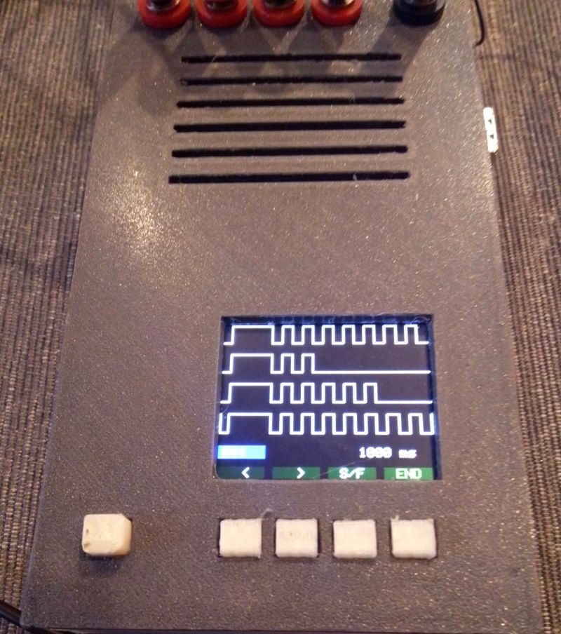
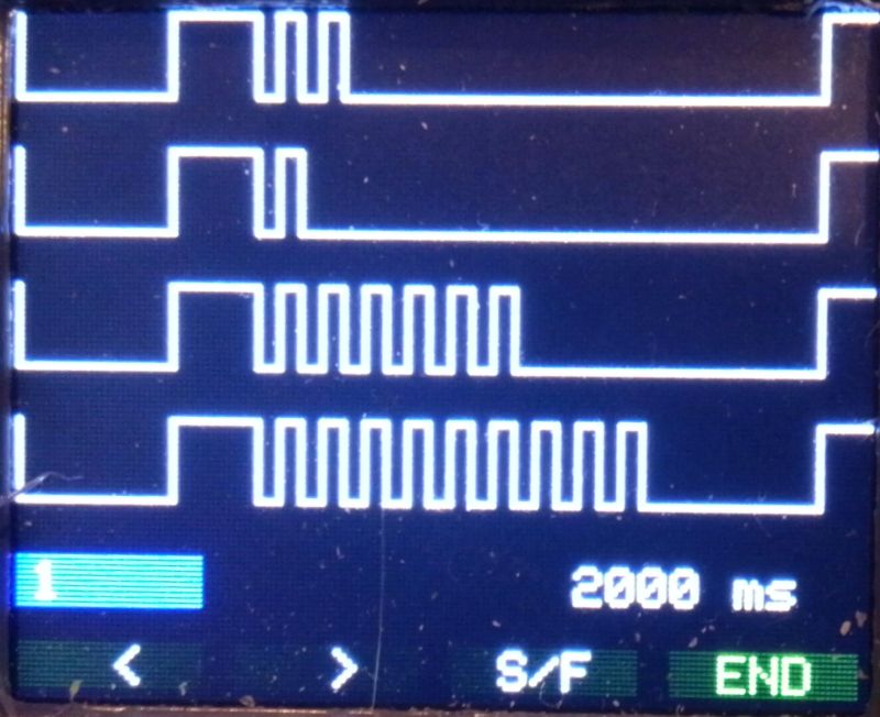
So here is a handheld device that displays on a 160x128 TFT colour screen simultaneously four digital inputs. The signals can be recorded and later displayed and explored back and forth as a continuous strip.
Project Overview
"Logic-Scope" is a rigorous implementation of Multi-Channel Logic Forensics and Asynchronous Waveform Recordation. Designed as a handheld diagnostic tool for complex mechatronic systems, this project enables the simultaneous monitoring of four independent TTL digital signals. The system features a deterministic logic-engine that captures signal-state harmonics and commits them to an AT24C256 EEPROM for longitudinal study. The build emphasizes craftsmanship through a custom-CNC-routed PCB, providing a stable, low-noise environment for high-fidelity signal-integrity diagnostics.
Technical Deep-Dive
The timebase (like on an oscilloscope) can be chosen: the whole width of the screen spans 200, 500, 1000, or 2000 milliseconds. Well, it appears painfully slow, I know. But this is all I could achieve. That could be a challenge for another developer, couldn't it?
Let's see what's going on...
- Logic-Sniffer & Signal-Capture Forensics:
- The TTL-Input Demodulation Diagnostics: The 4-channel array is calibrated for standard TTL logic-levels $(0-5\text{V})$. Forensics involve high-speed polling of the digital ports to detect state-transitions with microsecond precision. The diagnostics monitor the Transition-Harmonics, allowing the user to visualize pulse-widths across four selectable time-scales $(200\text{ms to } 2000\text{ms})$.
- Temporal Sweep-Window Heuristics: To balance the ST7735's rendering latency with signal detection, the system implements a Coordinated Drawing Diagnostic. Each horizontal pixel on the $160\times128$ screen represents a discrete temporal interval, ensuring that the visualized waveform strip accurately reflects the real-world logic-pulse forensics.
The signals to observe are plugged into the 4 red jacks. The inputs from left to right are (rather logically) displayed from top to bottom. The black jack has to be connected to a common ground. Turning on the device with the button on the left shows the home screen (to return to this screen, turn off and on).
The bottom bar labels the 4 buttons and the screen describes the options.
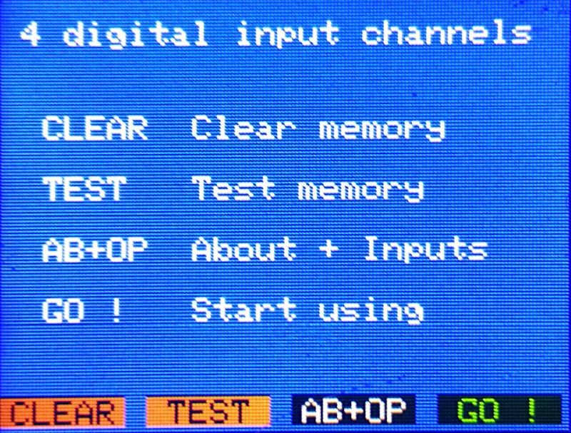
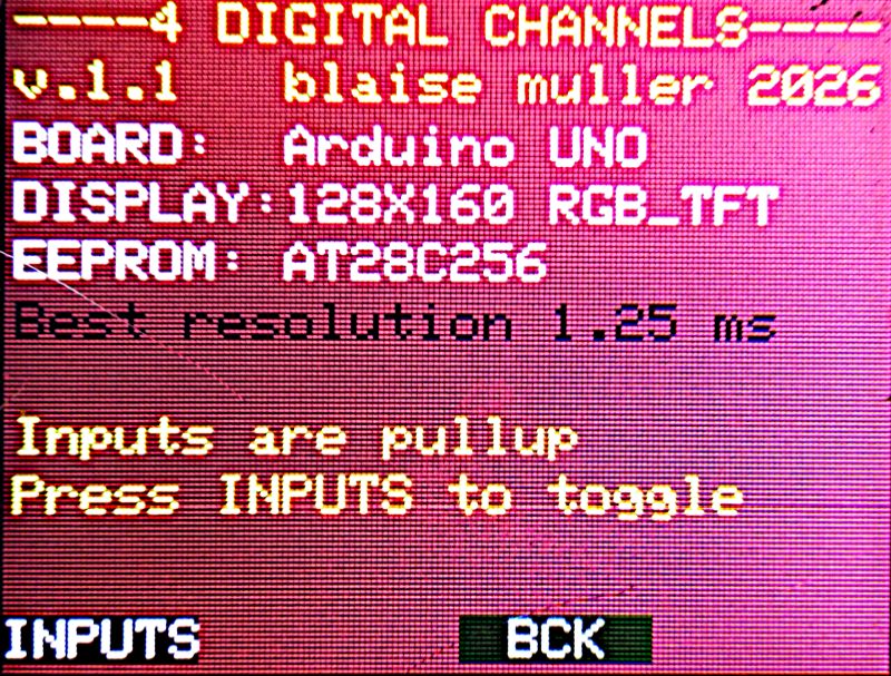
CLEAR and TEST should only be used if a failure in the EEPROM is suspected, each process takes several minutes. AB+OP is a traditional ABOUT screen, where an option was added. Here, the user can choose if the inputs are OPEN or PULLED UP.
GO! starts the application.
- EEPROM Telemetry & Replay Orchestration:
- AT24C256 Non-Volatile Forensics: Recorded signals are buffered into a $256\text{kbit}$ EEPROM bank. Forensics involve a page-writing strategy that organizes the logic-history into "120 Pages" of recordable waveform diagnostics.
- Scrubbing & Replay Harmonics: The HMI allows for exploratory forward/backward scrubbing of the recorded telemetry. The diagnostics focus on identifying faulty data-packets $(\text{visualized by a red indicator wire})$, providing a forensic overview of intermittent hardware failures or timing-glitches.
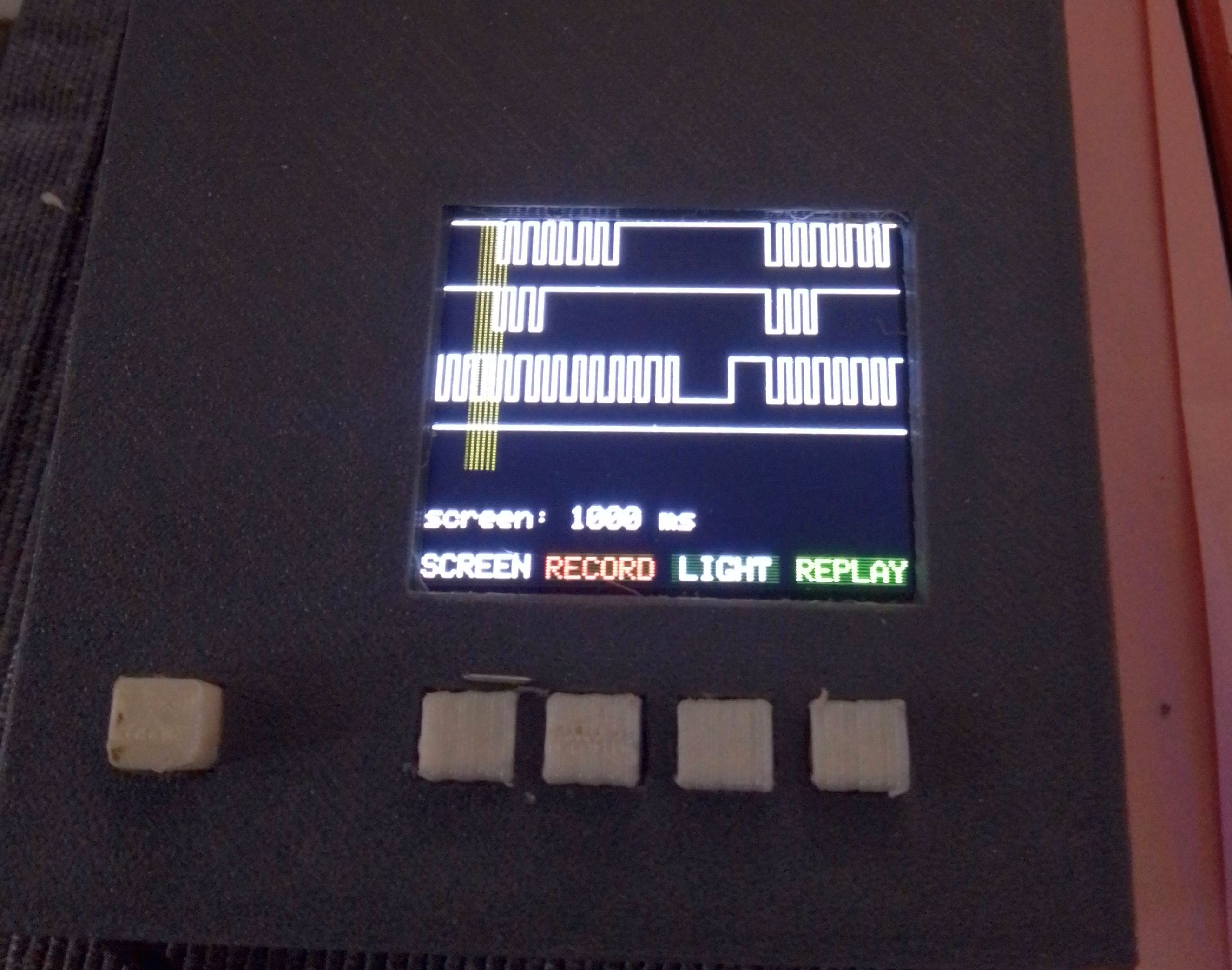
Button SCREEN changes the time scale.
Button RECORD starts recording the signals. They are still normally displayed. The same button turns into END to stop the recording. About 120 pages can be stored.
Button LIGHT sets the backlight. As the device is battery-operated, this can save much energy. But don't panic! The device can be powered via the USB port (in that case, turn off the power switch).
Button REPLAY displays the recorded data. A red line indicates faulty data.
Buttons <** and **> shift the display left or right.
Button S/F toggles slow or fast shifting.
Button END gets back to the main page.
That's it, more or less. Details can be discovered by using the device.
Engineering & Implementation
- CNC-Routed PCB & Structural Design Heuristics:
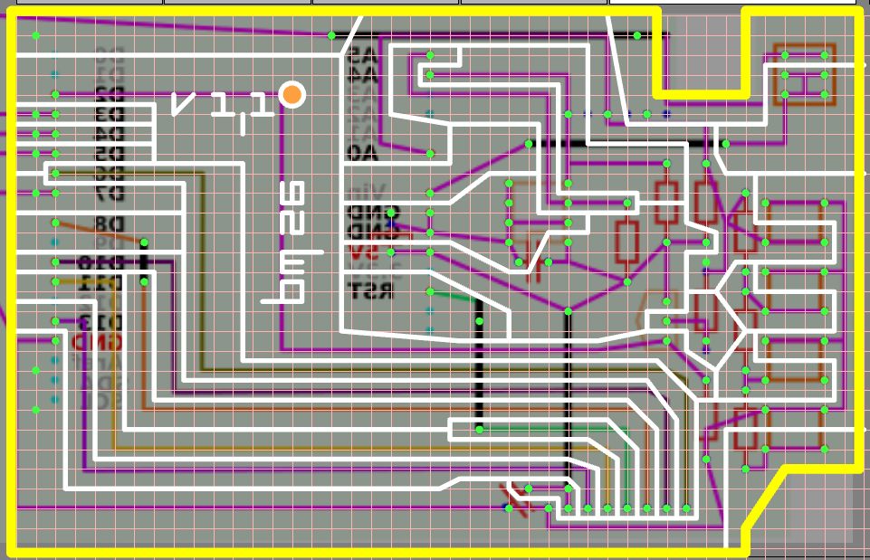
- Custom .NC Logic-Generation: The PCB was engineered using a custom-generated G-code strategy for a CNC-router. This forensics into the fabrication process ensures high-fidelity trace-engraving, eliminating the parasitic capacitance and chemical-residue harmonics found in traditional etching.
- Structural Mechatronic Diagnostics: The 3D-printed ABS enclosure provides the necessary mechanical stability for handheld use. Forensics into the jack-to-PCB interconnects ensure that the high-frequency digital inputs remain shielded from environmental electromagnetic interference.
- Energy-Rail Management & HMI Heuristics:
- Powering the device with a 9V battery requires rigorous efficiency diagnostics. The ST7735 backlight is orchestrated via a PWM-modulated logic-node $(\text{LIGHT button})$, allowing the user to optimize energy forensics for extended field-study without degrading the photonic output.
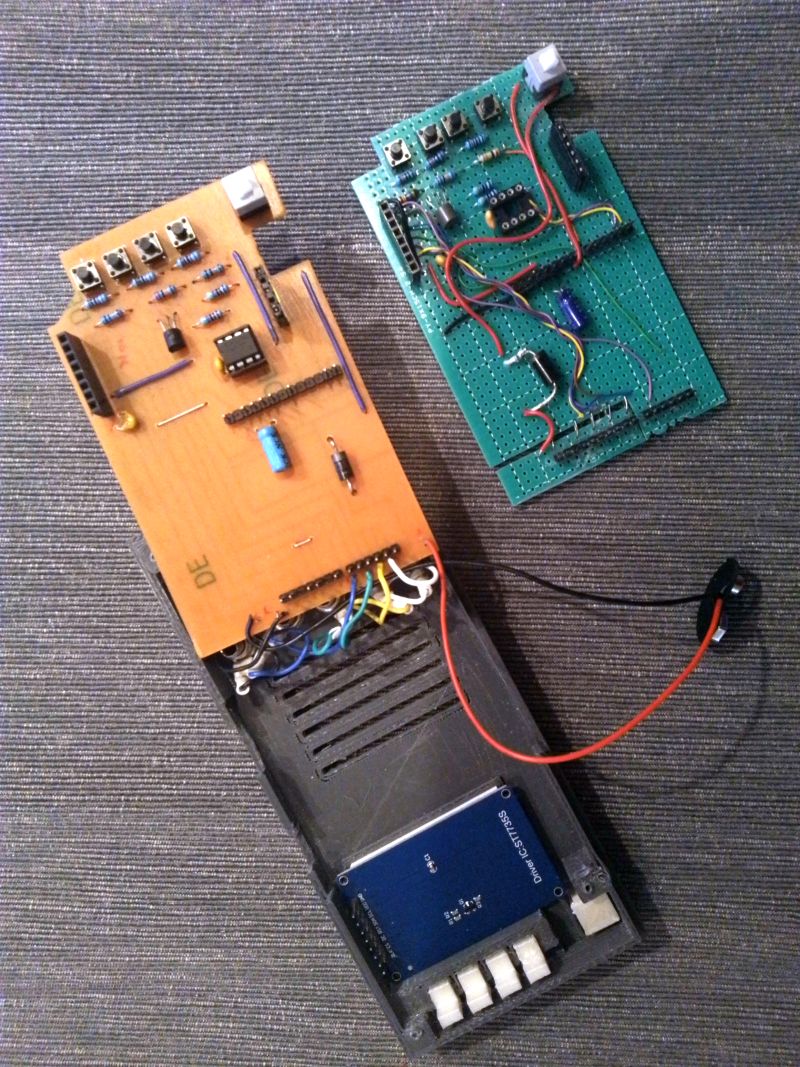
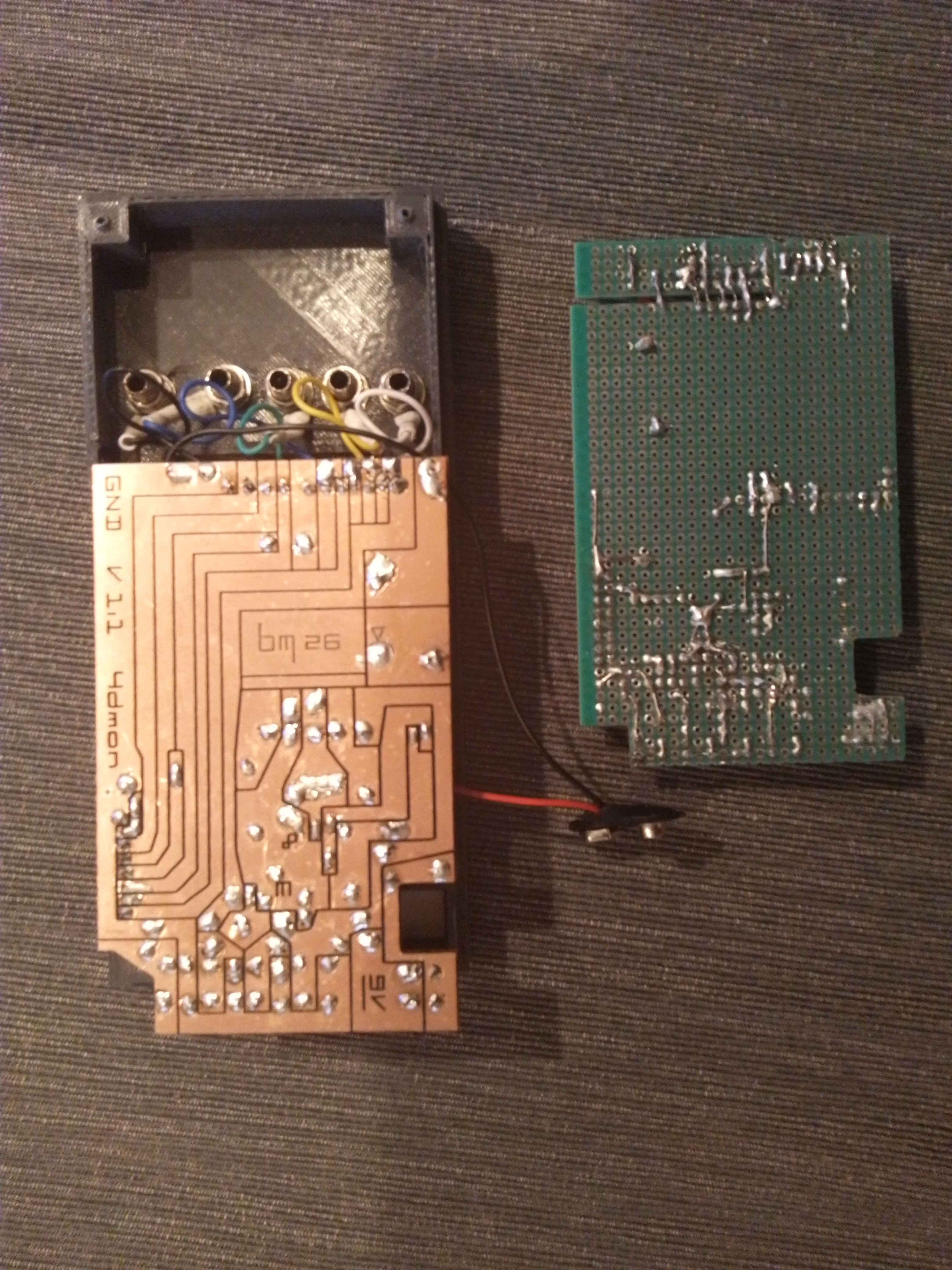
Have a look inside: the final result and the wild (green) PCB from the first prototype. As the wiring is very minimalistic, the primitive prototype worked perfectly. But, as the project was so simple, I wanted to spice it up somewhat and try to use my new CNC router. You may observe the unusual layout of the PCB. I'm an old man and remember that this way of designing PCB's was common in my youth. As it has apparently completely disappeared, I had to develop my own application to generate the .nc files for the router! The result makes me very happy: the whole process of engraving, drilling, and cutting out the PCB is sooo much faster! (OK, it only works with very simple layouts. But allow me the pride of showing off!)
Conclusion
Logic-Scope represents the pinnacle of Personal Instrumentation Design. By mastering EEPROM Telemetry Forensics and CNC-Fabrication Diagnostics, this project delivers a robust, portable logic-analyzer that provides professional-grade visibility into complex digital-signal orchestration.
Logic Clarity: Mastering multi-channel telemetry through signal forensics.