The lamp is completely programmed in Arduino and seeks to complete a a two mode lamp; automatic and manual mode.
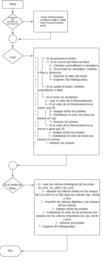
During the automatic mode, a photoresistor is toggled. If the photoresistor senses light, the mood lamp should stay at a color (you can easily pick this color on the code).
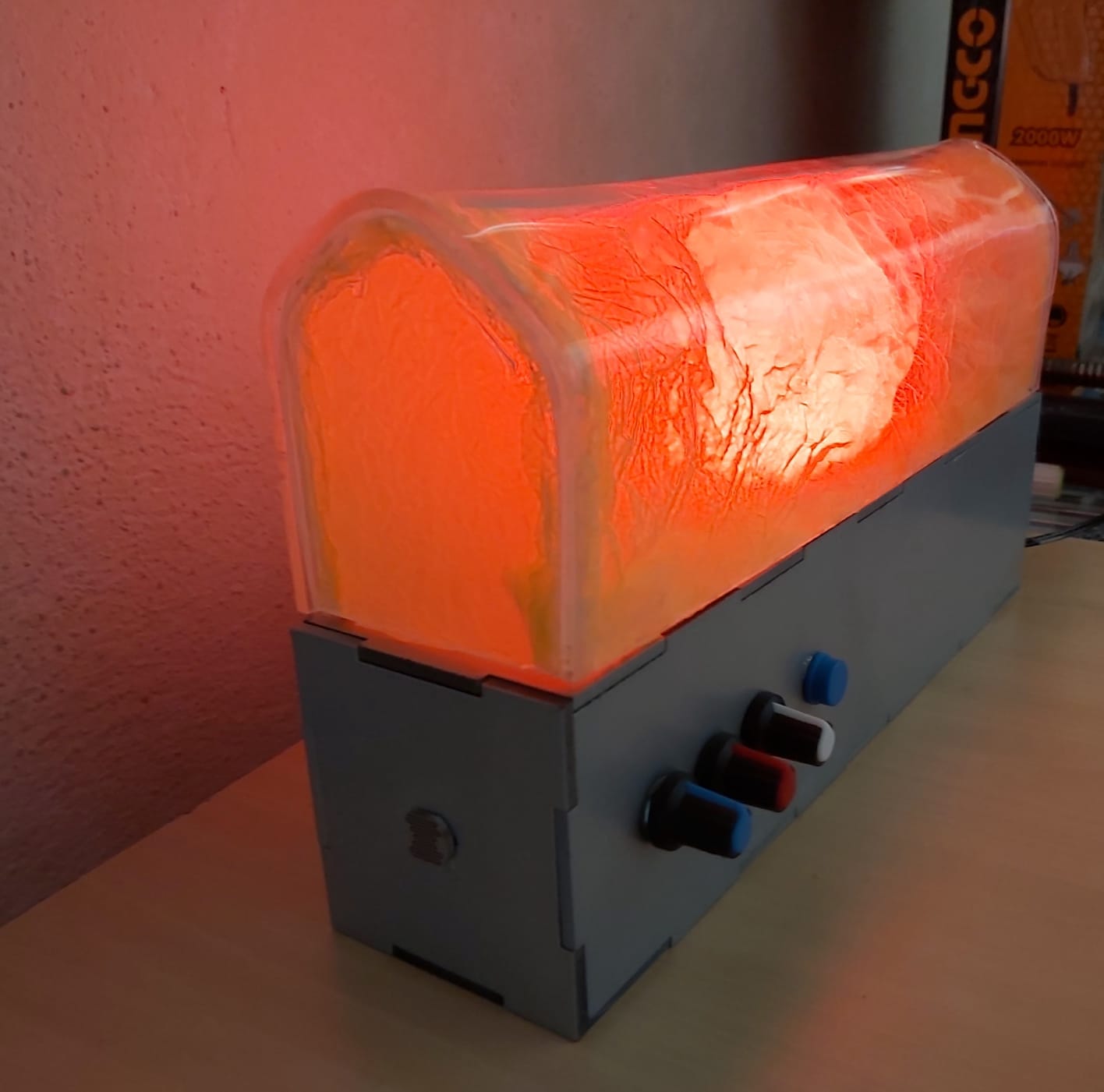
During the manual mode, the mood lamp should change colors when the potentiometers are manipulated by the user, there are three potentiometers in total.
When the user press a button, the modes should change from one to another.
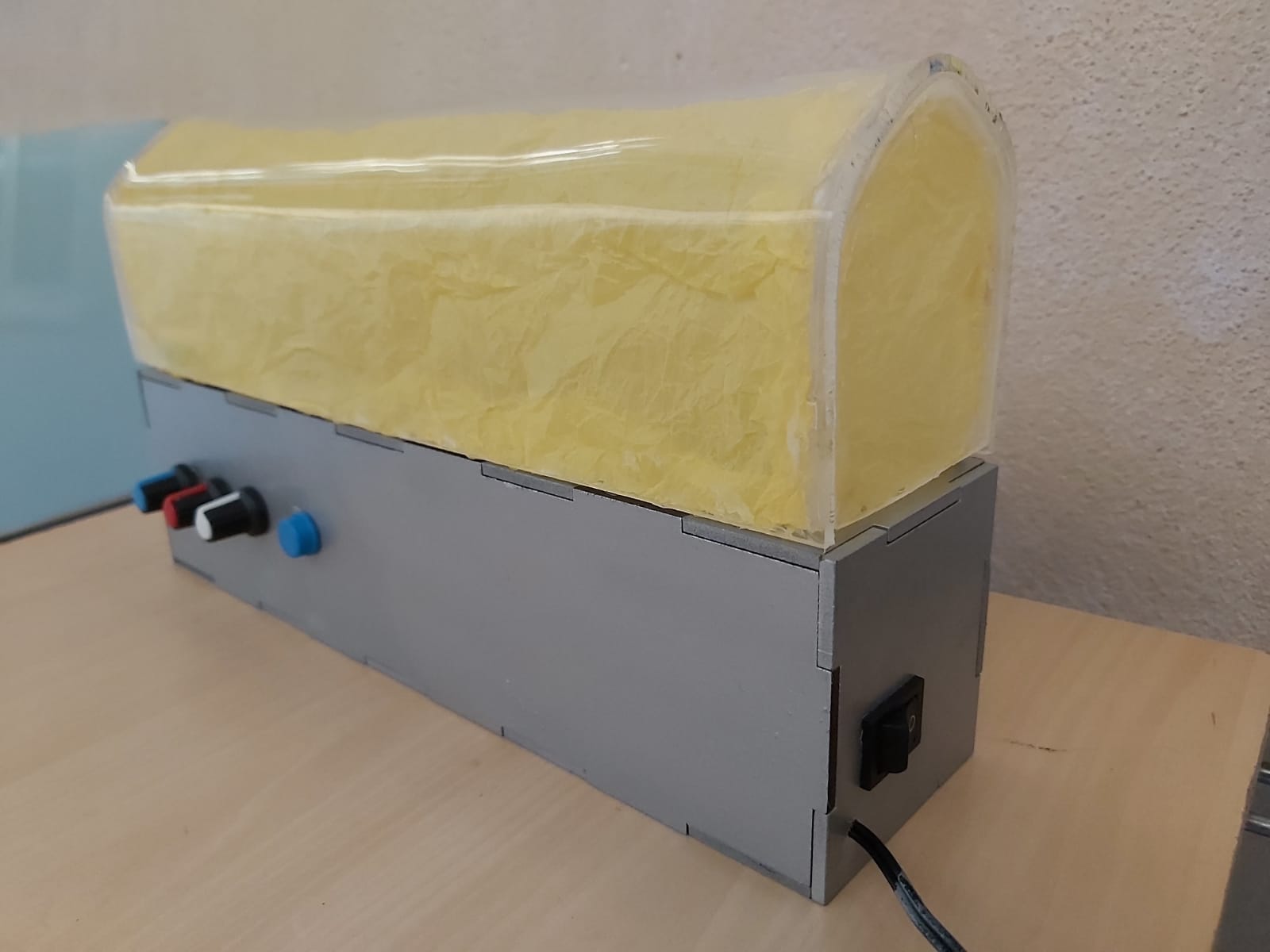
Finally, the mood lamp is connected to electricity, in case you want it to be connected all the time and just turn on/off the mood lamp completely you should be able to toggle a switcher at the side of the mood lamp.

EXPANDED TECHNICAL DETAILS
Digital Lighting Simulation
The UVG (Ultimate Visual Guide) Mood Lamp focuses on the art of color theory and ambient lighting design using virtual prototyping.
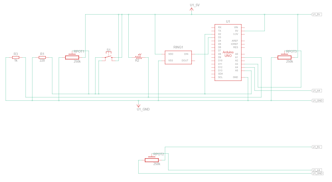
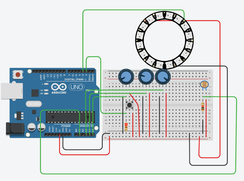
- Tinkercad Simulation: This project is primarily designed in a virtual environment. It uses an RGB LED (Common Cathode) and three potentiometers. The Arduino reads the analog inputs and generates corresponding PWM duty cycles for the Red, Green, and Blue channels.
- Virtual Circuitry: Demonstrates the vital role of current-limiting resistors (typically 220-330 ohms) in protecting LEDs from overcurrent, providing a safe playground for beginners to master color mixing logic.
Interactive Moods
- Pre-set Themes: Includes code for "Ocean," "Sunset," and "Forest" modes, where the lamp transitions smoothly between specific color palettes without manual input.
Steps to Make
- A 3D model of the lamp was created.
- Having dimensions defined it, we later made blueprints and used them in a laser cutting machine.
- Once printed, we proceeded to cut the necessary holes to incorporate the power supply, the button next to the potentiometers and the desired place for the photoresistor.
- The acrylic began to be molded and pasted with tissue paper so that the light covered more space along the length of the lamp.
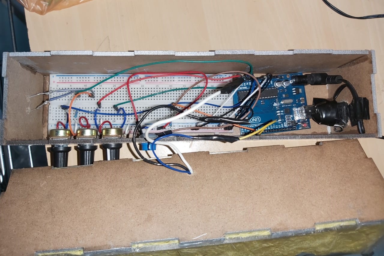
- The cables were soldered to the corresponding ports of the 4x4 matrix and the switcher was attached to the power source so that it allows the lamp to be turned on and off completely.
- The Arduino was physically connected to the board as shown in the images in the gallery below, taking into account the necessary space for the potentiometers, the button, the power source and the photoresistor.
- The base was then joined, already with all the circuit and elements mentioned above, to the acrylic and tissue paper structure.
- The code previously made in Tinker cad was incorporated and tests began.
- Done! Now you can enjoy your mood lamp on Arduino.