Project Overview
The "Dynamic RGB LED Chaser" is a foundational project that introduces the concepts of multi-pin control, PWM (Pulse Width Modulation), and rhythmic animation using an Arduino UNO. By orchestrating multiple RGB LEDs, this project goes beyond simple "blink" sketches to create complex, color-shifting sequences. It is an excellent vehicle for learning software engineering practices—such as using for loops and arrays to manage identical hardware objects—and understanding the electrical constraints of driving multiple high-current components simultaneously.
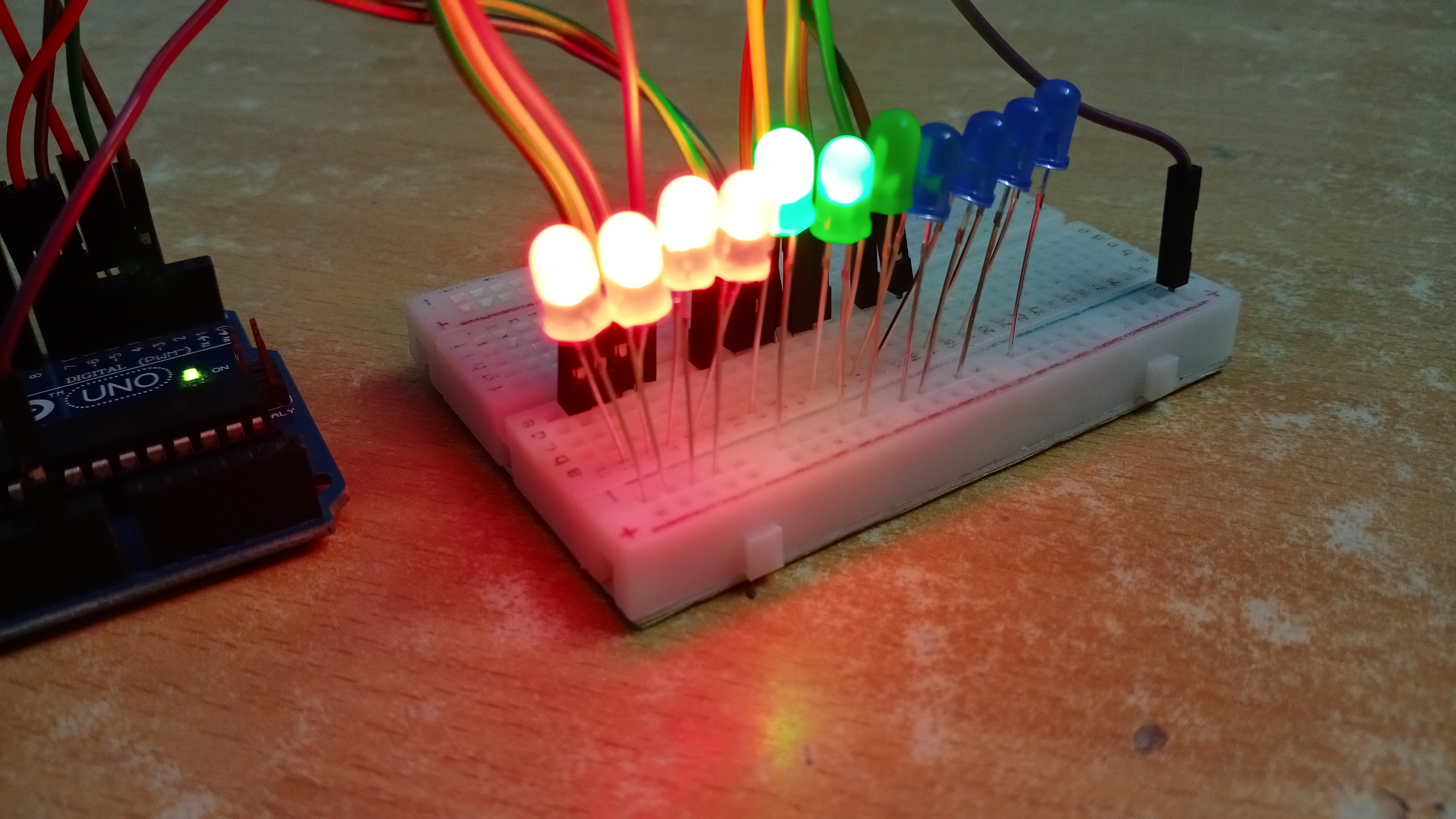
Multiple RGB Led Chaser
This Project Is about Build RGB LED chaser using arduino,
visit sparkbuzzer Press Here,
Technical Animation Architecture
- Array-Based Pin Mapping: To handle multiple LEDs efficiently, the firmware defines an array of pin numbers:
int ledPins[] = {2, 3, 4, 5, 6, 7};. This allows thesetup()andloop()functions to iterate over the pins programmatically, reducing the code footprint and making it easy to add more LEDs without duplicating logic. - Color Mixing Logic: Each RGB LED is essentially three separate LEDs (Red, Green, Blue) in a single package. By varying the intensity of each channel via
analogWrite(), the project can cross-fade between colors, creating a "rainbow" chase effect. - The "Chaser" Algorithm: The sequence is driven by nested loops. The outer loop selects which LED to activate, while the inner logic determines the specific color or transition speed. By shifting the "active" index globally, the visual effect of moving lights is created.
- Timing & Non-Blocking Delay: While this intermediate version uses
delay(), advanced variants often employmillis()based timing. This allows the Arduino to process user inputs or sensor data (like music beat detection) without pausing the animation.
Engineering & Hardware Features
- Current-Limiting Strategy: Driving multiple LEDs can be taxing on the Arduino's 500mA USB power limit. This project emphasizes the use of resistor banks to ensure that each individual LED channel draws only ~20mA, protecting the AtMega328P pins from overcurrent damage.
- Common Cathode vs. Common Anode: LEDs are polar. This project typically uses Common Cathode RGB LEDs, where the long pin is connected to Ground, and the R, G, and B pins are driven HIGH by the Arduino.
- Breadboard Optimization: The "Half Size" breadboard layout is optimized for visual impact, aligning the LEDs to create a continuous track. Jumper wires are used as a "bus" to provide a shared ground for all components in the chaser.
- Visual Debugging: The chaser acts as a manual tester for the breadboard connections. If a specific color or LED fails to light in sequence, it immediately highlights a loose connection or a reversed diode.