I love mining and I truly believe that blockchain and digital currencies will one day change the world. Cryptocurrency has played a significant role in my life and has made me a morning person, ha ha. Miners require 24 x 7 access to the Internet. Recently, I went on a short business trip and my router for some stupid reason stopped working. I lost complete access to my home network and my miners. When I returned from my trip, my only aim was to fix this issue by creating an "Internet Hardware Watchdog" that reboots the router whenever something silly happens to it.
Note: If you do any work with "mains power" such as 120v or 240v AC power wiring, you should always use proper equipment and safety gears and determine whether you have adequate skill and experience or consult a Licensed Electrician. This project is not intended for use by children.
Project Perspective
The NodeMCU Internet Hardware WatchDog is a sophisticated exploration of network technology and IoT interaction. By focusing on the essential building blocks—the ICMP ping-request stack and high-performance relay-dispatch logic—you'll learn how to communicate and synchronize connectivity tasks using specialized software logic and a robust hardware setup.
The Logic

Let me first explain the logic to you. In a nutshell, in this setup I am going to ping "www.google.com" and as soon as the ping drops I will reboot the router.
To achieve this, the NoduMCU first connects to the WiFi network and then pings 8.8.8.8 (www.google.com).If it receives a successful ping, one out of the 3 blue LED patterns is displayed.
If the ping fails, 5 more retries are given before rebooting the router. The reason I am NOT rebooting the router straightaway is to avoid false positive ping fail responses. However, once the "fail_count" counter becomes 5, NodeMCU turns off the router by pulling the armature of the relay module. The armature of the relay is held for 15 seconds before releasing it so that the router is properly power cycled. Once the armature is released, the system waits for a minute before sending the next ping request. This gives enough time to the router to successfully perform its POST activities.
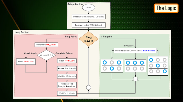
The above steps are then endlessly repeated in the loop section of the code.
Technical Implementation: ICMP Pings and Autonomous Power-Cycling
The project reveals the hidden layers of simple sensing-to-reboot interaction:
- Identification layer: The NodeMCU (ESP8266) acts as a high-resolution digital eye, measuring internet packet connectivity status via
pingcommands. - Conversion layer: The system uses the high-speed WiFi protocol to receive data and coordinate mission-critical sensing tasks.
- Control Interface layer: A 5V Relay Module provides mechanical feedback for network status checks (e.g., Reboot Triggered).
- Processing Logic: The Arduino code follows a "fail-safe" (or reboot-dispatch) strategy: it interprets ping timeouts and matches relay states to provide safe and rhythmic network stability.
- Communication Dialogue Loop: Status messages are sent rhythmically to the Serial Monitor during initial calibration to coordinate status.
Components Required
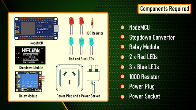
For this project we need: NodeMCU, Stepdown Converter, Relay Module, 2 x Red LEDs, 3 x Blue LEDs, 100Ω Resistor, Power Plug and a Power Socket
Hardware-Network Infrastructure
- NodeMCU ESP8266: The "brain" of the project, managing multi-directional WiFi sampling and coordinating relay and LED sync.
- 5V Relay Module: Providing a clear and reliable "Switching Link" for the power cable.
- LEDs: Providing visual status feedback for each successful "Ping Mission."
- Step-down Converter: Powers the NodeMCU and relay module from the mains supply.
Schematic
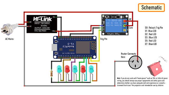
Now, let's put the components together exactly the way I have shown in the schematic diagram. Be very careful while handling AC Main Power sockets and cables. The Stepdown Converter powers the NodeMCU and the Relay Module. LEDs are connected to the Digital pins of the microcontroller. The relay acts as a switch and switches on or off the router based on the ping response.Please make sure you check the pins of your relay module before hooking it up to the circuit.
The Board
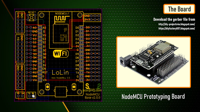
So, this is how my board looks like in 2D and 3D.I basically have created a replica of the NodeMCU Prototyping Board which you can buy from AliExpress for about $4 to $6.
Components Assembly
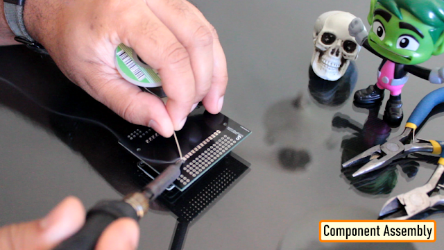
Lets start by soldering the NodeMCU to the board. Since I care a lot about my Sensors and Microcontrollers, I am not going to solder them directly to the board. Instead I am soldering 'female pin headers' to the board which will house all the sensors and the microcontrollers in them.
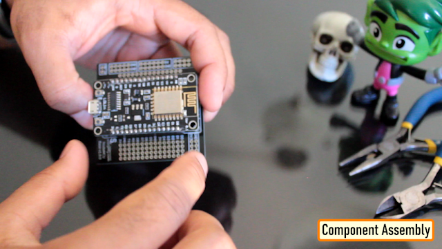
I initially thought of soldering the LEDs directly on the board however something clicked in my mind and I went ahead and soldered them on a separate perfboard and then soldered the perfboard to the NodeMCU development board. Well, this was totally unnecessary.
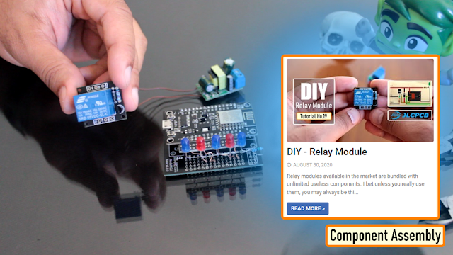
Once the LEDs were in place, my next step was to solder the step-down-converter and the relay-module to the board. If you want to know how I created this relay module, please check out my tutorial no. 19 DIY Relay Module : https://www.youtube.com/watch?v=3n69b4sdDjk the video and the blog post links are in the description below. Next, I made a hole in the transparent box and glued the power socket into it. Well I created a bit of mess while gluing the socket and accidentally glued the box on to my dining table, silly me. I also drilled a hole at the back of this box, for the cable that will connect to the AC Main power supply.
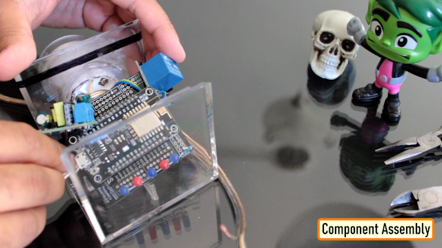
Pretty much that's it. Once again, I would like to warn you guys: If you do any work with the "main power" such as 110v or 240v AC, you should always use proper equipment and safety gears and determine whether you have adequate skill and experience or consult a Licensed Electrician. This project is not intended for use by children.
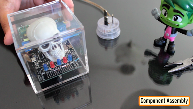
To conclude the setup, I added a small skull inside the acrylic box. This skull has been sitting on my desk just collecting dust for over a year, ha ha.
The Code
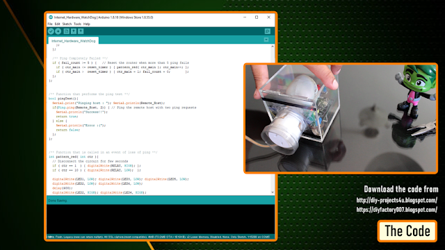
Now, let's have a look at the code. You can download the code and other resources from the links provided in the description below.To Run the attached code you need to download and install the "ESP8266Ping" library. You can either download it from GitHub or from the link provided in the description below. Unzip and copy the archive to the Arduino's Library Folder and change the board type to ESP8266 in the Arduino IDE and select NodeMCU. The code starts by including all the libraries and variables on top. Then in the setup() section I have defined all the pin modes and have made a connection to the WiFi router. In the loop() section I am performing a ping test and based on the test result I am either blinking the blue LEDs or power cycling the router.
WatchDog Automation and Interaction Step-by-Step
The network monitoring process is designed to be very efficient:
- Initialize Workspace: Correctly set your relay and LEDs on your board and connect them properly to the NodeMCU pins.
- Setup WiFi Sync: In the Arduino sketch, initialize the
WiFi.begin()and define the target server (e.g., 8.8.8.8) to coordinate the sensing. - Internal Dialogue Loop: The system constantly performs high-performance periodic pings and updates the relay status in real-time based on your connection settings.
- Visual and Data Feedback Integration: Watch your serial dashboard automatically become a rhythmic status signal, pulsing and following your location settings.
[!IMPORTANT] To avoid accidental reboots, always perform a multi-ping validation (e.g., 5 consecutive failures as shown in the logic diagram) in the code; always ensure you have an appropriate Delay After Reboot logic in the loop!
Future Expansion
- OLED Identity Dashboard Integration: Add a small OLED display to show "Last Reboot (h:m:s)" or "Uptime."
- Multi-sensor Climate Sync Synchronization: Connect a specialized "Current Sensor (ACS712)" to perform higher-precision "Power Consumption Tracking" wirelessly via the cloud.
- Cloud Interface Registration Support Synchronization: Add a specialized web-dashboard on a smartphone over WiFi/BT to precisely track and log total network history.
- Advanced Velocity Profile Customization Support: Add specialized logic to the code to allow triggers to be changed automatically based on user-defined rules!
Internet Hardware WatchDog is a perfect project for any science enthusiast looking for a more interactive and engaging network tool!
Thanks
Thanks again for checking my post. I hope it helps you.If you want to support me subscribe to my YouTube Channel: https://www.youtube.com/user/tarantula3 Blog Posts:Internet Hardware WatchDog : https://diy-projects4u.blogspot.com/2021/12/internet-hardware-watchdog.html DIY Relay Module : http://diy-projects4u.blogspot.com/2020/08/diy-relay-module.html Video:
- Internet Hardware WatchDog : https://youtu.be/L5nLfEjTePA
- DIY Relay Module : https://www.youtube.com/watch?v=3n69b4sdDjk
Other Resources:
- Code: https://drive.google.com/file/d/1HyTUMUBDK0neO854XMl3dyy5ceoeTImw/view?usp=sharing
- ESP8266Ping Library : https://github.com/dancol90/ESP8266Ping.git
- ESP8266Ping Library : https://drive.google.com/file/d/1uFfY5wW7-oWRNjP_XaBj2IM189M1n1FK/view?usp=sharing
- Schema: https://drive.google.com/file/d/1gn2ZhMp5Uz4YDv5GjxgIq1rtzh-21Rwe/view?usp=sharing
- Gerber File: https://drive.google.com/file/d/1l0bszJ0AV7S9s-y9jTWGcw9MrWayVJxZ/view?usp=sharing
- Flowchart: https://drive.google.com/file/d/1CL3g0nT1IZfdL8MZqN_PB-mKC9k_JfWH/view?usp=sharing
Support My Work:
- BTC: 1M1PdxVxSTPLoMK91XnvEPksVuAa4J4dDp
- LTC: MQFkVkWimYngMwp5SMuSbMP4ADStjysstm
- DOGE: DDe7Fws24zf7acZevoT8uERnmisiHwR5st
- ETH: 0x939aa4e13ecb4b46663c8017986abc0d204cde60
- BAT: 0x939aa4e13ecb4b46663c8017986abc0d204cde60
- LBC: bZ8ANEJFsd2MNFfpoxBhtFNPboh7PmD7M2 Thanks, ca again in my next tutorial.