//made by Sujal Vasoya
//CD 4511 IC for 7 segment display
//pin 2,3,4,5 in first IC,pin 6,7,8,9 in second IC
//pin 10 in IR sensor out pin
#define ir 10
int count=0;
int j=1;
int i=1;
void setup() {
 pinMode(ir,INPUT);
 pinMode(2,OUTPUT);
 pinMode(3,OUTPUT);
 pinMode(4,OUTPUT);
 pinMode(5,OUTPUT);
 pinMode(6,OUTPUT);
 pinMode(7,OUTPUT);
 pinMode(8,OUTPUT);
 pinMode(9,OUTPUT);
 Serial.begin(9600);
}
void loop()
{
 int in_value=digitalRead(ir);
 if(in_value==LOW)
 {
   Serial.print("count=");
   Serial.println(count);
   number2(j);
   Serial.print("j=");
   Serial.println(j);
    if(j==0)
    {
      number1(i);
      Serial.print("i=");
      Serial.println(i);
      i++;
    }
   j++;
   if(j==10)
   {
     j=0;
   }
   count++;
   if(count==100)
   {
     count=0;
     i=1;
     j=1;
     number1(0);
     number2(0);
   }
   delay(150);
 }
}
void number1(int x)
{ if(x==0)
 {
 digitalWrite(2,0);
 digitalWrite(3,0);
 digitalWrite(4,0);
 digitalWrite(5,0);
 }
 if(x==1)
 {
 digitalWrite(2,1);
 digitalWrite(3,0);
 digitalWrite(4,0);
 digitalWrite(5,0);
 }
 if(x==2)
 {
 digitalWrite(2,0);
 digitalWrite(3,1);
 digitalWrite(4,0);
 digitalWrite(5,0);
 }
 if(x==3)
 {
 digitalWrite(2,1);
 digitalWrite(3,1);
 digitalWrite(4,0);
 digitalWrite(5,0);
 }
 if(x==4)
 {
 digitalWrite(2,0);
 digitalWrite(3,0);
 digitalWrite(4,1);
 digitalWrite(5,0);
 }
 if(x==5)
 {
 digitalWrite(2,1);
 digitalWrite(3,0);
 digitalWrite(4,1);
 digitalWrite(5,0);
 }
 if(x==6)
 {
 digitalWrite(2,0);
 digitalWrite(3,1);
 digitalWrite(4,1);
 digitalWrite(5,0);
 }
 if(x==7)
 {
 digitalWrite(2,1);
 digitalWrite(3,1);
 digitalWrite(4,1);
 digitalWrite(5,0);
 }
 if(x==8)
 {
 digitalWrite(2,0);
 digitalWrite(3,0);
 digitalWrite(4,0);
 digitalWrite(5,1);
 }
 if(x==9)
 {
 digitalWrite(2,1);
 digitalWrite(3,0);
 digitalWrite(4,0);
 digitalWrite(5,1);
 }

}
void number2(int y)
{ if(y==0)
 {
 digitalWrite(6,LOW);
 digitalWrite(7,LOW);
 digitalWrite(8,LOW);
 digitalWrite(9,LOW);
 }
 if(y==1)
 {
 digitalWrite(6,HIGH);
 digitalWrite(7,LOW);
 digitalWrite(8,LOW);
 digitalWrite(9,LOW);
 }
 if(y==2)
 {
 digitalWrite(6,LOW);
 digitalWrite(7,HIGH);
 digitalWrite(8,LOW);
 digitalWrite(9,LOW);
 }
 if(y==3)
 {
 digitalWrite(6,HIGH);
 digitalWrite(7,HIGH);
 digitalWrite(8,LOW);
 digitalWrite(9,LOW);
 }
 if(y==4)
 {
 digitalWrite(6,LOW);
 digitalWrite(7,LOW);
 digitalWrite(8,HIGH);
 digitalWrite(9,LOW);
 }
 if(y==5)
 {
 digitalWrite(6,HIGH);
 digitalWrite(7,LOW);
 digitalWrite(8,HIGH);
 digitalWrite(9,LOW);
 }
 if(y==6)
 {
 digitalWrite(6,LOW);
 digitalWrite(7,HIGH);
 digitalWrite(8,HIGH);
 digitalWrite(9,LOW);
 }
 if(y==7)
 {
 digitalWrite(6,HIGH);
 digitalWrite(7,HIGH);
 digitalWrite(8,HIGH);
 digitalWrite(9,LOW);
 }
 if(y==8)
 {
 digitalWrite(6,LOW);
 digitalWrite(7,LOW);
 digitalWrite(8,LOW);
 digitalWrite(9,HIGH);
 }
 if(y==9)
 {
 digitalWrite(6,HIGH);
 digitalWrite(7,LOW);
 digitalWrite(8,LOW);
 digitalWrite(9,HIGH);
 }
}
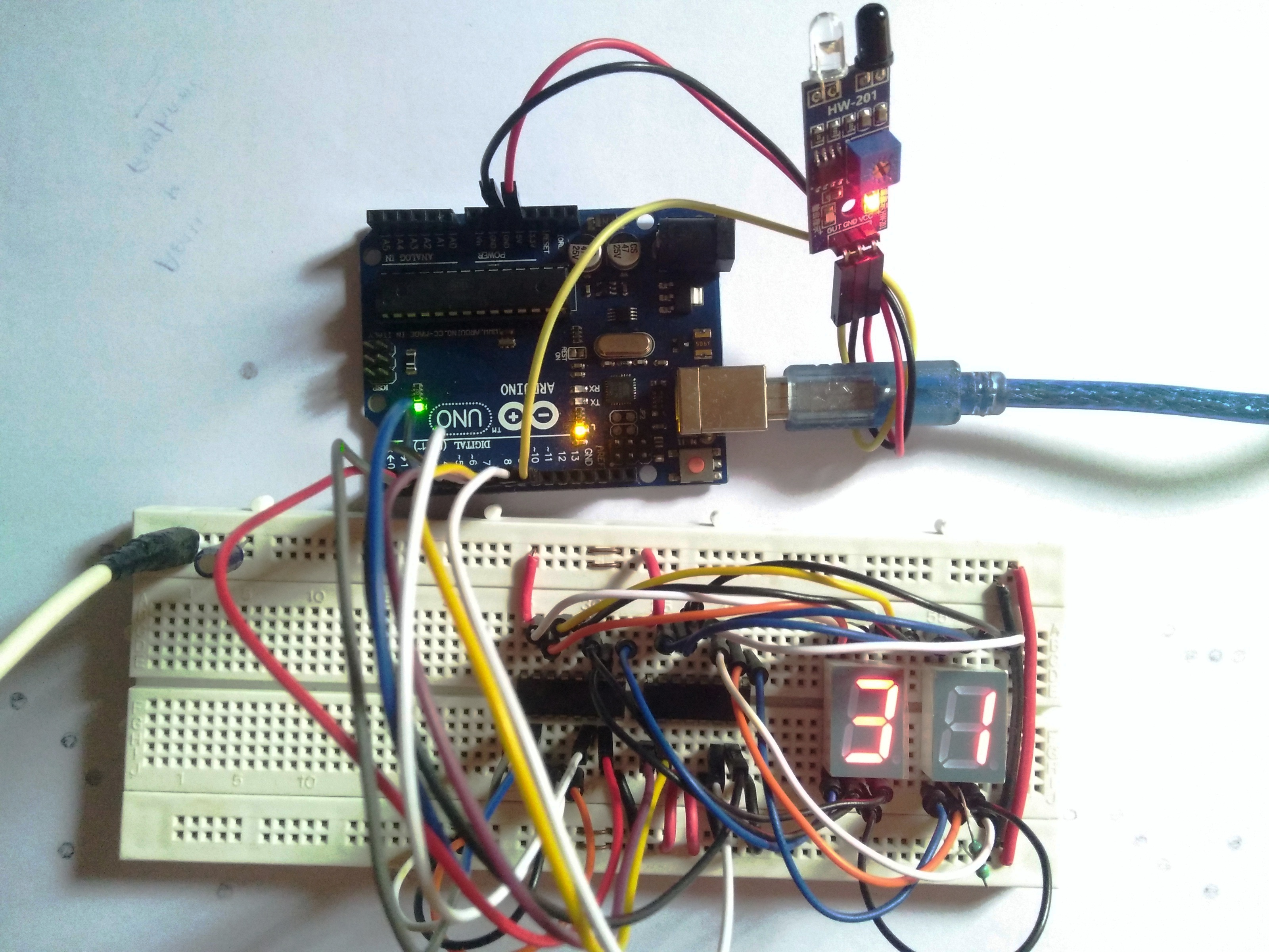
Project Perspective
Object counter with IR sensor is the fundamental and innovative "Automation Bridge" for modern electronics developers. By focusing on the essential building blocks—the IR-beam reflection logic and the synchronized BCD-to-segment output mapping—you'll learn how to orient yourself and automate your counting tasks using a specialized software logic and a robust basic setup.
Technical Implementation: IR Reflection and Digital Driver Logic
The project reveals the hidden layers of simple sensing-to-count interaction:
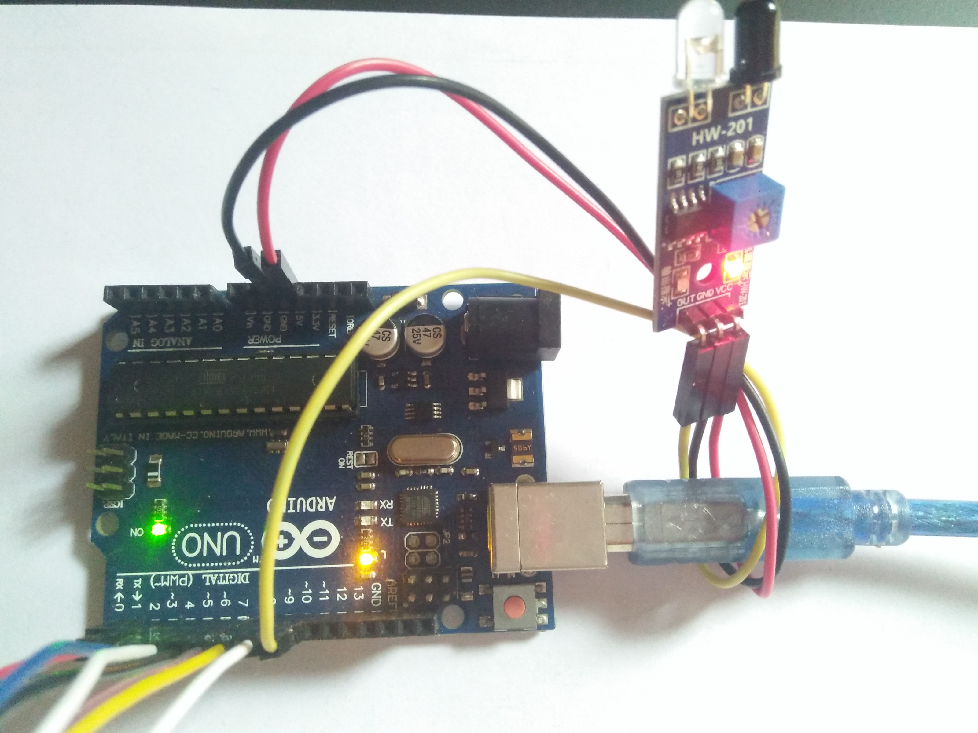
- Identification layer: The IR Proximity Sensor acts as a high-resolution spatial eye, measuring the presence of obstacles and generating a digital pulse upon detection.
- Conversion layer: The system uses high-speed digital pins to receive these binary pulses for mission-critical sensing tasks.
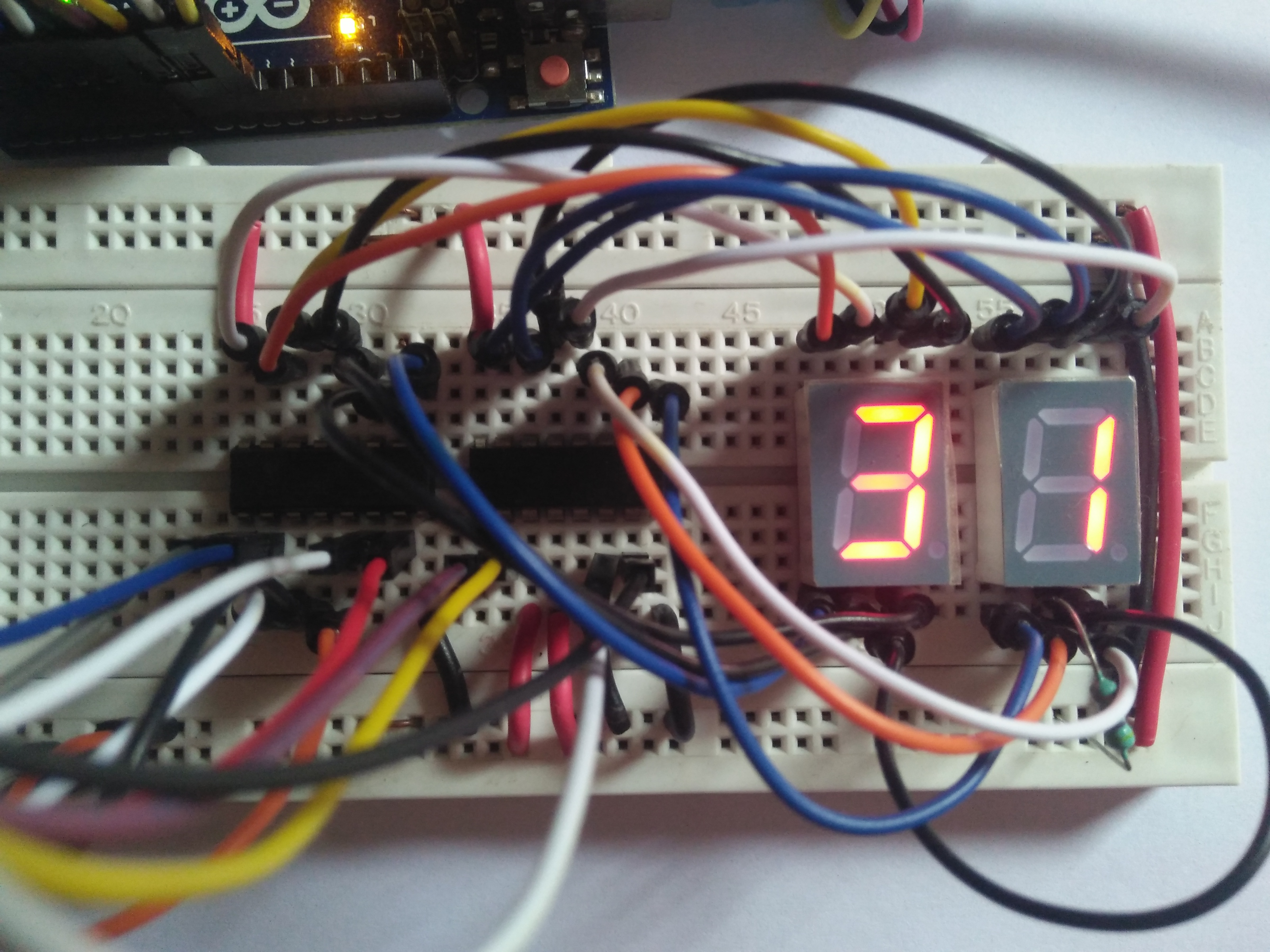
- Visualization Interface layer: Dual 7-Segment Displays provide a high-definition visual data dashboard for your count status check (e.g., 0 to 99).
- Driver Logic layer: Two CD4511 ICs provide a BCD-to-7-segment conversion, automating the status display during operation.
- Processing Logic: The Arduino code follows a "lookup-dispatch" (or counter-dispatch) strategy: it interprets the sensor pulses and matches them to BCD digital outputs to provide safe and rhythmic object counting.
- Communication Dialogue Loop: Counter bits are sent rhythmically to the Serial Monitor for real-time debugging and status monitoring.
Hardware-Automation Infrastructure
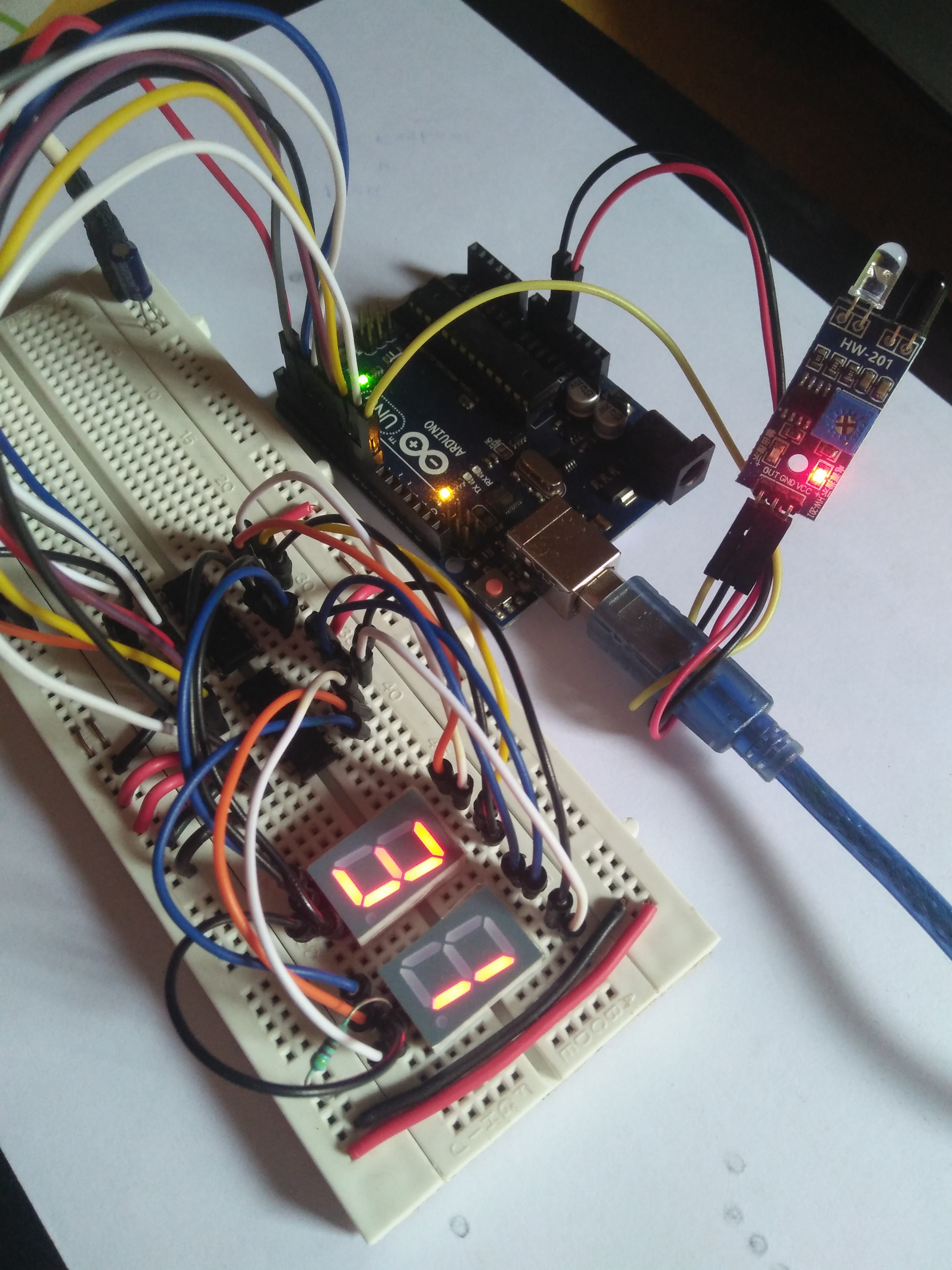
- Arduino Uno: The "brain" of the project, managing the multi-directional digital sampling and coordinating the driver ICs and sensor sync.
- IR Proximity Sensor: Providing a clear and reliable "Measuring Link" for any point on a conveyor or doorway.
- CD4511 Driver ICs: Providing a high-capacity and reliable physical interface for the first successful "Display Mission."
- 7-Segment Displays: Providing high-precision and reliable "Visual Link" for the units and tens digits.
- Breadboard: A convenient way to prototype the first automation-electronics circuit and connect all components without soldering.
- Micro-USB Cable: Used to program the Arduino and provides the primary interface for the system controller.
Counter Automation and Interaction Step-by-Step
The IR-driven counting process is designed to be very user-friendly:
- Initialize Workspace: Correctly set up your IR sensor and driver ICs inside your breadboard and connect them properly to the Arduino pins.
- Setup High-Speed Sync: In the Arduino sketch, initialize the
pinMode()pins and define the BCD digit mapping in thesetup()function. - Internal Dialogue Loop: The system constantly performs high-performance digital checks and updates the counter status in real-time based on your sensor triggers.
- Visual and Data Feedback Integration: Watch your 7-segment dashboard automatically become a rhythmic status signal, pulsing and following your location settings.
Future Expansion
- OLED Identity Dashboard Integration: Add a small OLED display on the side to show "Batch Total" or "Battery (%)".
- Multi-sensor Climate Sync Synchronization: Connect a specialized "Bluetooth Module" to perform higher-precision "Cloud-Logging" wirelessly.
- Cloud Interface Registration Support Synchronization: Add a specialized web-dashboard on a smartphone over WiFi/BT to precisely track and log the total counting history.
- Advanced Velocity Profile Customization Support: Add specialized "Deep Learning (vCore)" to the code to allow triggers to be changed automatically based on user-defined patterns!
Object Counter with IR Sync is a perfect project for any science enthusiast looking for a more interactive and engaging automation tool!
[!IMPORTANT] The IR Sensor requires an accurate ambient light calibration; always ensure you have an appropriate Resistor Matching for each segment of the LED display!