Oplà Alarm clock
#cloudgames2022
This project turns your Arduino Oplà IoT kit into a clock. Through the Arduino cloud, you can enable/disable the alarm and choose the wake-up time.
Modern Smart Display Integration
The Oplà Alarm Clock utilizes the high-resolution Arduino Oplà IoT Kit to create an internet-synchronized, feature-rich bedside companion.
- NTP Time Synchronization: Instead of a drift-prone hardware crystal, the Oplà connects to Network Time Protocol (NTP) servers via WiFi. This ensures the clock is always accurate within milliseconds and adjusts for Daylight Savings automatically.
- Capacitive Touch UI: Navigates alarms and settings through the Oplà's circular capacitive touch sensors. These triggers are mapped in software to change the RGB ring colors and display the alarm status on the sharp 1.3" OLED screen.
Customization
- Weather API Integration: Upon waking up, the clock can display current weather data fetched from an API, providing a seamless "Smart Bedside" experience without needing a smartphone.
Cloud configuration
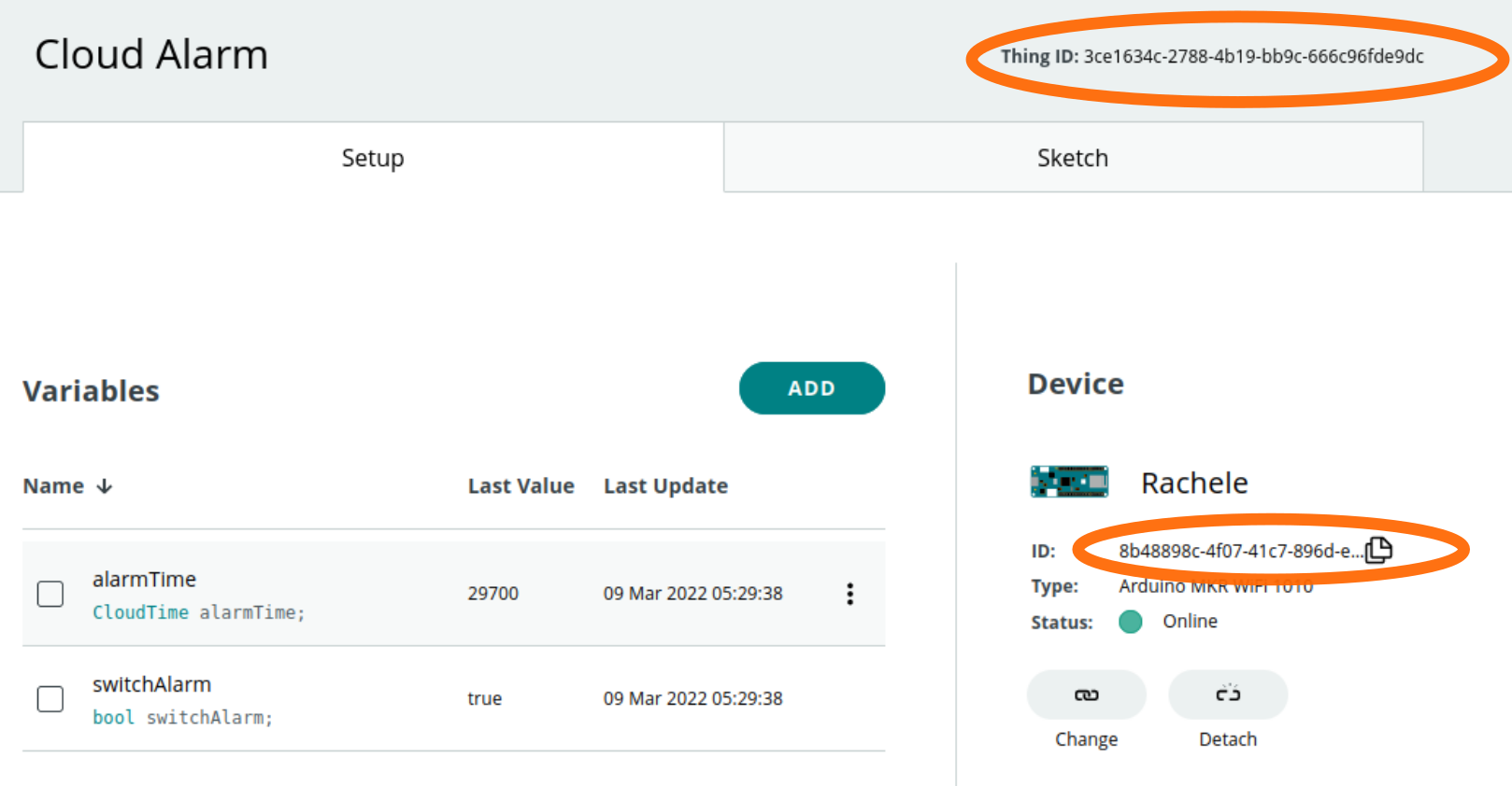
The project makes use of the Arduino Cloud to set the alarm. As a first step you have to create a new "Thing" and add two variables to it:
- alarmTime a CloudTime object. It represents the time when the alarm will fire. CloudTime is a way to track time as a running total of seconds. This count starts at midnight.
- switchAlarm a bool variable. True if the alarm is set false if not.
Below you can see an image of how your "Thing" should look like. Before going on, be sure to have a device attached to it.
Create the dashboard
Once the "Thing" is set up you can build the Dashboard. This is how it should look like:
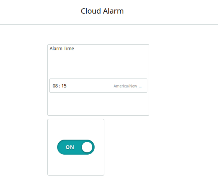
The two components need to be linked to the variables that you have just created in the "create Thing" panel.
Install the external libraries
Before compiling the code be sure to install the following libraries and their dependencies in the Arduino IDE:
- Arduino_MKRIoTCarrier
- RTCZero
Configure the secrets
Open the arduino_secrets.h file and fill the fields:
- SECRET_SSID
- SECRET_PASS
with your WI-FI credentials.
You also need to link your board to the Arduino Cloud, complete the following fields:
- THING_ID
- BOARD_ID
with the tokens "Thing ID" and "Device ID" available on the "Thing" page.
Compile the Sketch
Your environment is ready, connect the Oplà to your computer and upload the code.
Software explanation
The code makes use of the internal Real-Time Clock (RTC) to keep accurate tracking of the time. The correct time is retrieved from a Network Time Protocol (NTP) server after the WI-FI connection is established. Once the time is set there is no need to be connected anymore WI-FI. The Software keeps on checking that the time is still accurate over time, querying the NTP server at regular intervals.
The Arduino Cloud provides the interface to Disable/Enable the alarm and to change the alarm time.
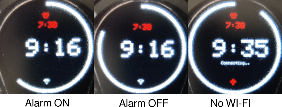
In the picture below you can see the different board statuses: alarm ON/OFF and WI-FI ON/OFF. The red time is the alarm time set from the Arduino Cloud.
The program makes use of time interrupts to fire the alarm at the exact time, this functionality is provided directly from the internal RTC:
void setAlarm() {
 rtclock.disableAlarm();
 rtclock.detachInterrupt();
 if (switchAlarm) {
   uint alarm_time_second = alarmTime;
   uint raw_minutes = alarm_time_second / 60;
   uint8_t clock_hour = raw_minutes / 60 - GMT;
   uint8_t clock_minute = raw_minutes % 60;
   if (clock_hour >= 24) {
     clock_hour -= 24;
   } else if (clock_hour < 0) {
     clock_hour += 24;
   }
   rtclock.setAlarmTime(clock_hour, clock_minute, 0);
   rtclock.enableAlarm(rtclock.MATCH_HHMMSS);
   rtclock.attachInterrupt(alarmMatch);
   Serial.println("Alarm set");
   return;
 }
 Serial.println("Alarm UNset");
}
The function setAlarm is executed every time the alarm change. The first two calls to the internal RTC:
rtclock.disableAlarm();
rtclock.detachInterrupt();
remove any interrupt attached if any.
Then, if the alarm is enabled:
rtclock.setAlarmTime(clock_hour, clock_minute, 0);
rtclock.enableAlarm(rtclock.MATCH_HHMMSS);
rtclock.attachInterrupt(alarmMatch);
The interrupt is set to be triggered when the time match hours, minutes and seconds. In this way, it will be repeated every day.
The alarm sound is made using the buzzer included in the Oplà carrier board (yes there is a buzzer!!). Here's how to play it:
 if (play_alarm) {
   if ((current_millis - prev_sound > 1000)) {
     prev_sound = current_millis;
     tone(carrier.Buzzer.getPin(), 500, 500);// async
   }
 }
The buzzer will stop playing when a button from of the Oplà carrier is pressed:
 carrier.Buttons.update();
 if (carrier.Buttons.onTouchUp(TOUCH0) or
     carrier.Buttons.onTouchUp(TOUCH1) or
     carrier.Buttons.onTouchUp(TOUCH2) or
     carrier.Buttons.onTouchUp(TOUCH3) or
     carrier.Buttons.onTouchUp(TOUCH4)
    ) {
   Serial.println("Touched Down a button");
   play_alarm = false;
 }
Finally, the Oplà screen is updated by a dedicated object responsible to print the time and move the seconds' bar. There is no need to enter in the detail of this component, the most important thing to mention is that it is updated in the main loop every second:
if ((current_millis - date_previous_millis) >= date_interval) {
   date_previous_millis = current_millis;
   screen.render();
}
Set your timezone
The internal RTC time is synced to the Greenwich Mean Time (GMT) you might need to correct it to match your location. To do that, you can change the timezone in the main file opla_alarm.ino like:
const int GMT = +1;
Special Thanks
This project was made to participate in the Arduino Cloud Challenge 2022. Thanks to Arduino for allowing me to participate!
Contribution
You can find this sketch and other related ones on github.