WHO AM I? WHY I DID IT?
I'm a mechanical engineer and I developed this project for my degree thesis. Naturally, creating an Orifice Plate from zero is not so easy, because you need to study Technical Physics (in detail Fluid dynamics). But, don't worry, I'll try to explain you how it works and how you can compute the mass flow within a pipe.
All the information are provided by UNI ISO 5167 2003 1 - 2.
I hope this project could help some Engineer or Science lovers. For any questions, don't hesitate to contact me!
WHAT DO YOU NEED TO KNOW?
Physics, Fluid dynamics (Reynold's number, Bernoulli equation), Numerical Analysis.
WHAT DO YOU NEED?
- An Orifice Plate (there are different types of it, the model "D and D/2 tappings" is the easiest to build, so I recommend it to you, but if you want to learn more about the other prototypes, check the UNI ISO 5167-1-2 2003)
- Arduino UNO
- MPX 5050dp
- thermocouple MAX 6675
HOW DOES IT WORK?
An orifice plate is a device which allows the user to calculate the axial velocity (and so the mass flow) of a fluid, within a pipe. For example, it is used in power stations, labs or airplanes (Pitot Tubes)!
In this case, I've built the model: "D and D/2 tappings".
One of the most important physics law involved in this process is the "Bernoulli's law".
I'll try to explain how you can adopt it in this particular case:
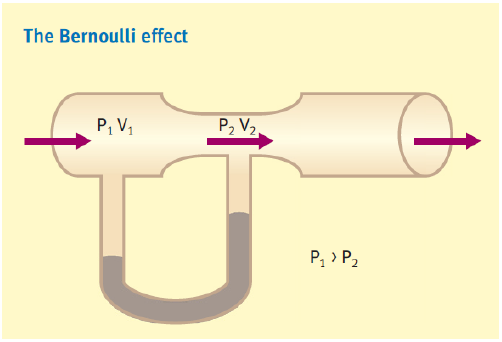
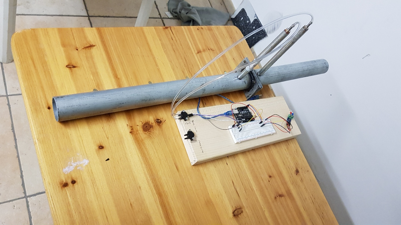
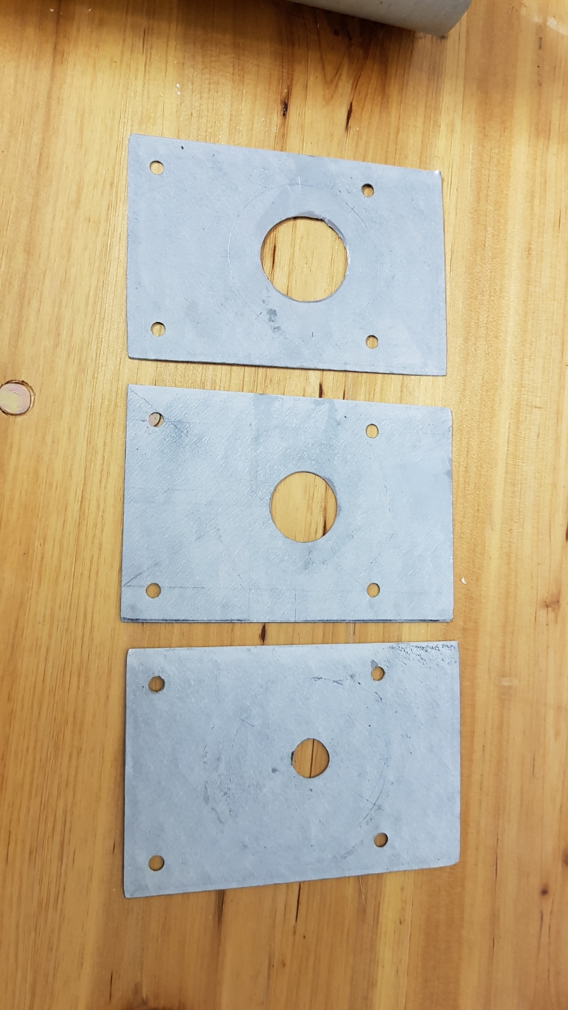
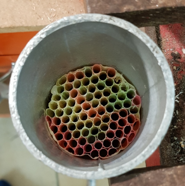
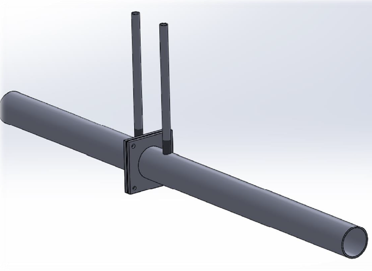
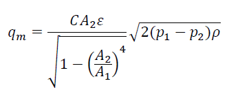
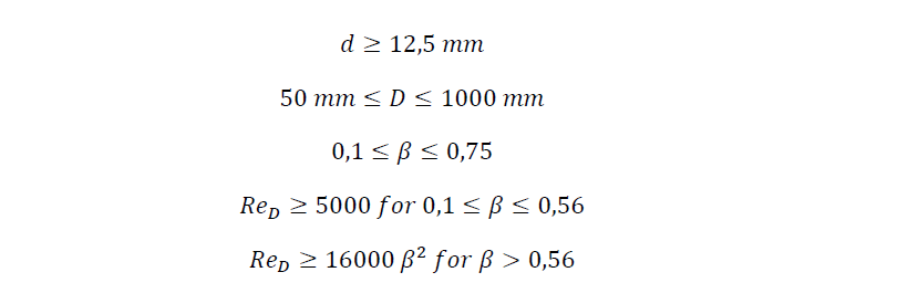
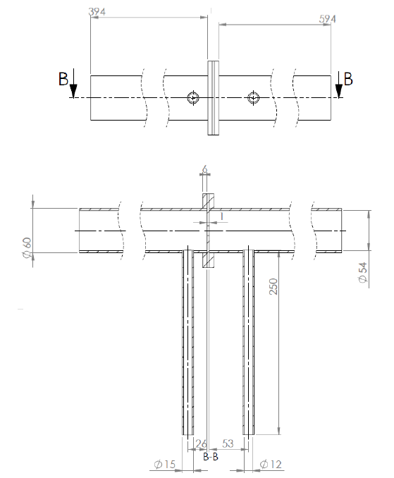
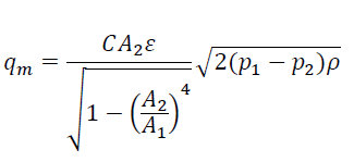
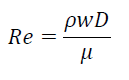
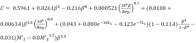
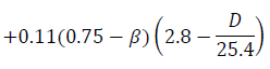
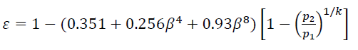
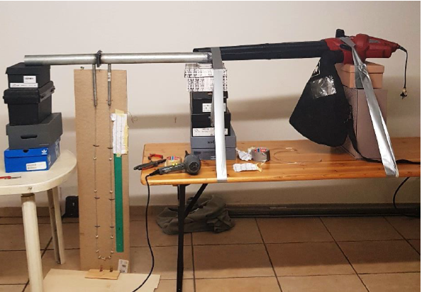
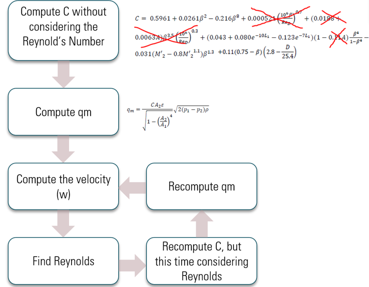
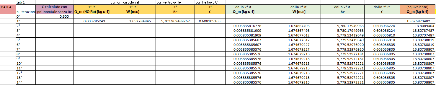
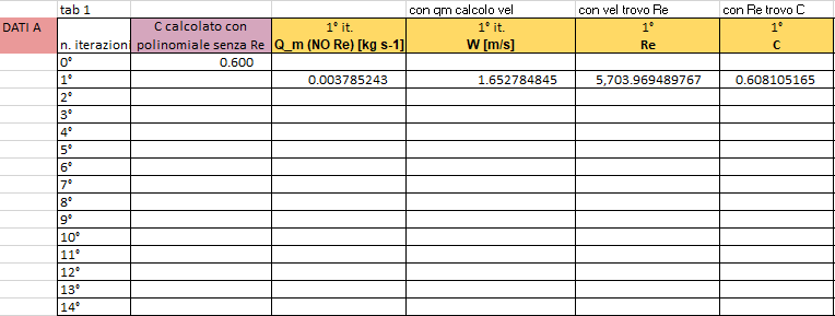
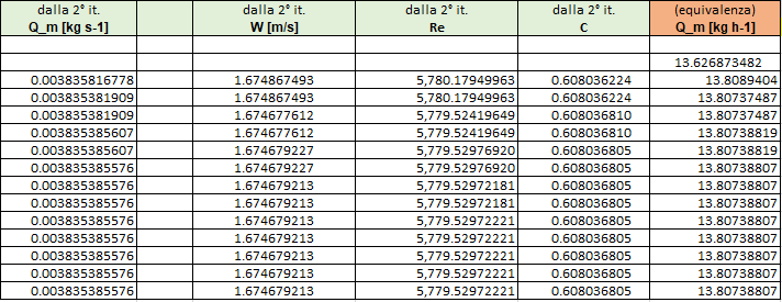
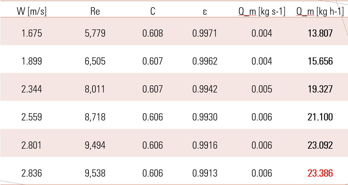
In an horizontal pipe, we can identify two sides ( in this picture it is identified by 1 and 2). When the pipe section decreases, the axial velocity increases from the section 1 to 2 (so v1 Shown below, the equation: from this we can obtain this formula: where: The Pressure drop and density will be found with Arduino, C and qm with numerical analysis and 𝜀 with its formula. From my thesis ( Ref. UNI ISO 5167 2003) : I chose the following dimension. For the orifice, I took in consideration three different diameters:12.93 mm, 24 mm, 31 mm. qm [kg/s] = w (axial velocity) [m/s]= qm/A1 ReD [adim] = where 𝜇 is dynamic viscosity C [adim] = (Where: L1~1, L'2~0.47, M'2 = 2*L'2/(1-𝛽), A = (19000*𝛽/ReD)^0.8) and if D<71.12 mm 𝜀 [adim] = where k is the coefficient of adiabatic expansion. Unfortunately, cause to Covid-19, I could not enjoy the laboratories of UniMore, so I used a fan to create the flow. Before taking the measurement, I built a "U pressure gauge", to calibrate the pressure sensor. At the end, for different fan's velocity, I've detected different pression drops and I've made a numerical analysis for each one. The calculation was carried out with excel. I took in consideratiom different pression values and then I made the numerical analysis for each value. Repeat the last four steps as long as the values converge within a specific tolerance. ex. P1-P2= 1000 Pa, d=12.93 mm. (from left to right). d=12.93 mm d=24 mm d=31 mm If you want to know how to compute the error, I can advice you to read UNI ISO 5167-1 2003. This is the formula: I'll show you my values of uncertainties. d=12.93 mm where "ro" is the density. This project uses an Arduino to measure the flow rate of liquids or gases through a pipe using the principle of differential pressure. Here there are some images of the project caught from my thesis : "Progettazione e realizzazione di un misuratore di portata massica su piattaforma hardware open source". THANKSTO MY UNIVERSITY, PROFESSORS AND ASSISTENTS.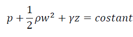
CONSTRUCTION REQUIREMENT (D&D/2 tappings)
ALL THE MOST IMPORTANT FORMULAS USED
HOW DO YOU GET THE MEASUREMENT?
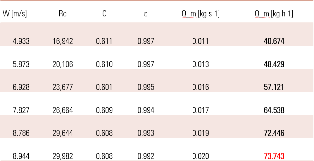
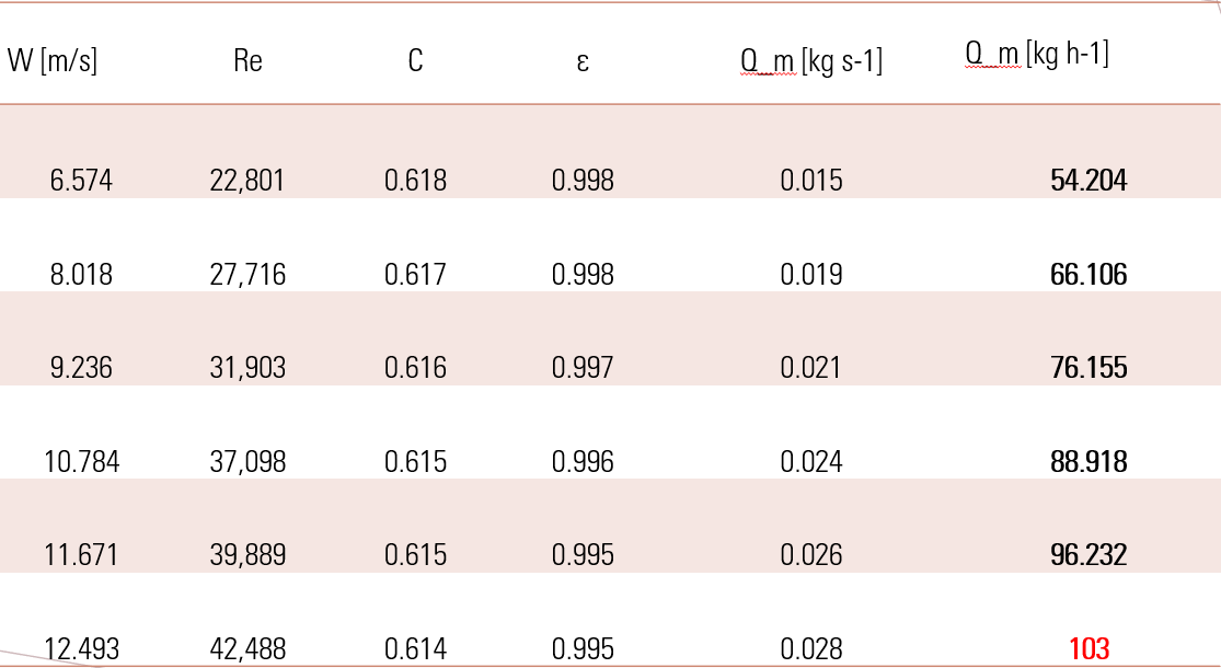
NUMERICAL ANALYSIS
MY RESULTS
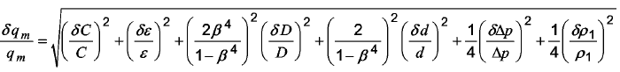
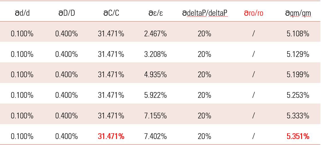
UNCERTAINTIES OF THE MEASUREMENT OF THE FLOW RATE
EXPANDED TECHNICAL DETAILS
Industrial Fluid Measurement
High-Speed Sampling
MY EXPERIENCE