Project Overview
"Otto-Link" is a comprehensive study in Bipedal Gait Forensics and Infrared Telemetry Diagnostics. Based on the open-source Otto DIY architecture, this project elevates the platform by implementing a customized dual-microcontroller command structure. By decoupling the kinetic input (joystick) from the bipedal executor (the robot), Otto-Link simulates a professional-grade wireless control interface. The project explores the complex synchronization required to transform simple rotational servo movement into stable, iterative walking patterns.
Introduction
In this report we will explain the operation of a bipedal robot driven by microcontrollers and controlled by a remote, able to walk and turn around.
Goal
The machines and projects must include the following features: • use an Arduino microcontroller board (UNO, Leonardo, 101); • request at least the use of an input sensor; • generate at least one output interfacing with the real world, which can be visual (LED, screens) or physical (moving motors); • use at least one device not explained in class, it can be a sensor or a motor and its pilot card.
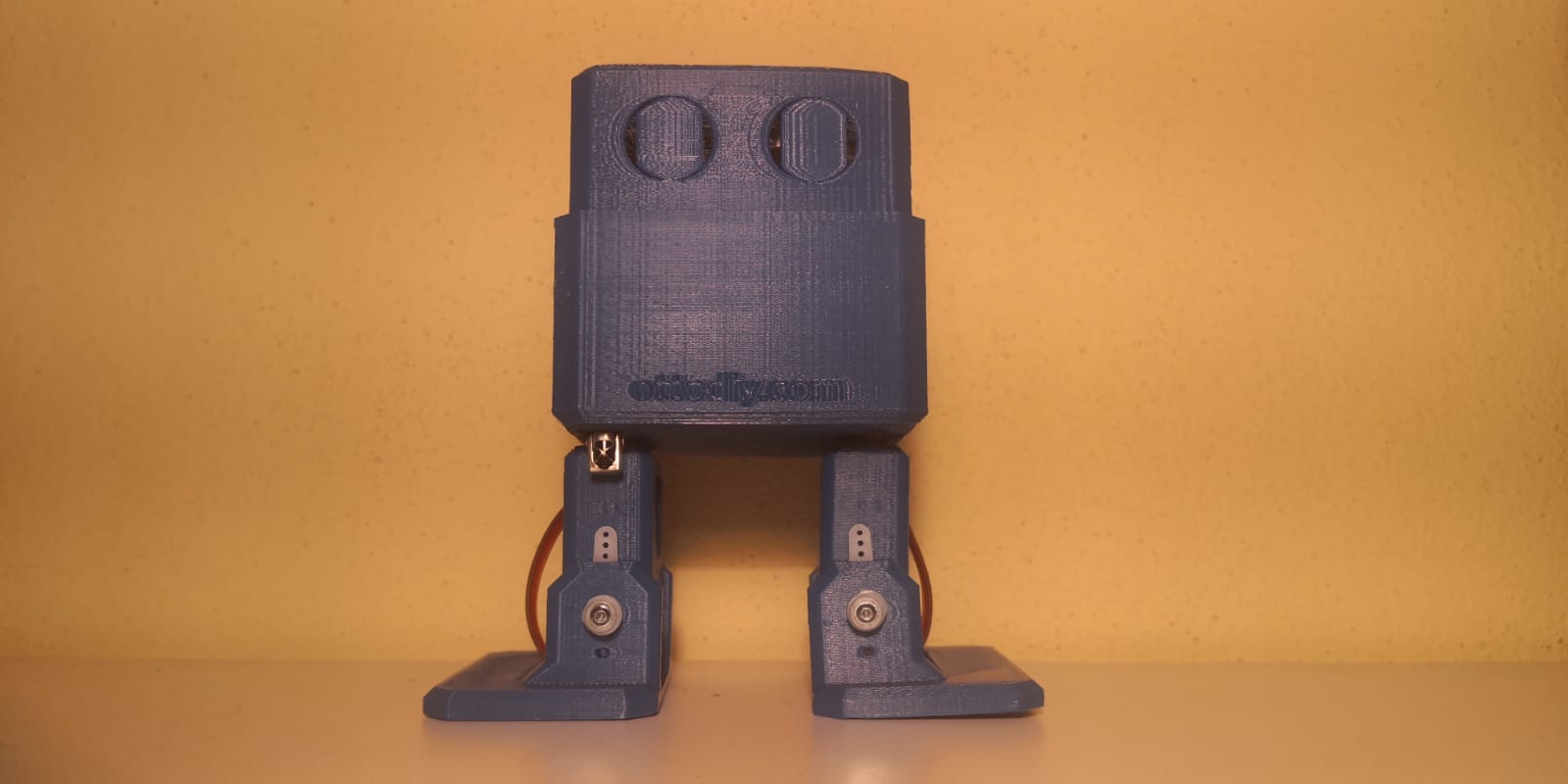
The project we decided to build is a toy bipedal robot (taking the "Otto DIY" open source project as an example) able to walk and turn around using an Arduino board which is controlled by IR signals sent by another Arduino board (which will work as a remote control).
Used Material
The components necessary for the realization of the project are the following ones:
- 2x Microcontroller (Arduino UNO, Elegoo Nano);
- 4x Micro servo SG90;
- IR LED;
- IR receiver VS1838B;
- joystick module;
- 100Ω resistance;
- Arduino nano expansion board;
- Jumper cables;
- PLA pieces (obtained by 3D printing).
The printed pieces’ 3D drawing files were downloaded from the website “Thingiverse”, as “Otto DIY” is an open source project. The servos and the IR receiver don’t require any resistance as it’s integrated in the components. To make the robot’s wirings easier we mounted the Elegoo Nano on an expansion board.
Technical Deep-Dive & Functioning
To make the bipedal robot we used 2 microcontrollers. The first one is an Elegoo Nano board connected to the joystick module and to the IR LED to assume the function of a remote control: it calculates the position of the joystick to understand where the robot has to go (so, which code has to be sent). The second microcontroller is the “mind” of the robot: it controls the movements of the 4 servos based on the infrared signals received by the sensor.
- Mechatronic Bipedal Kinematics:
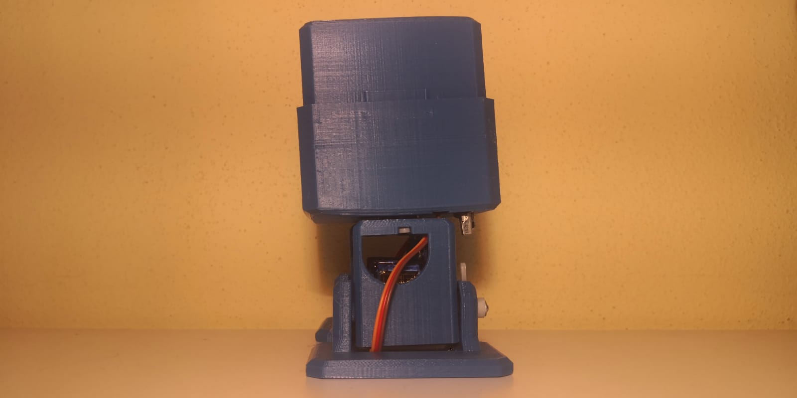
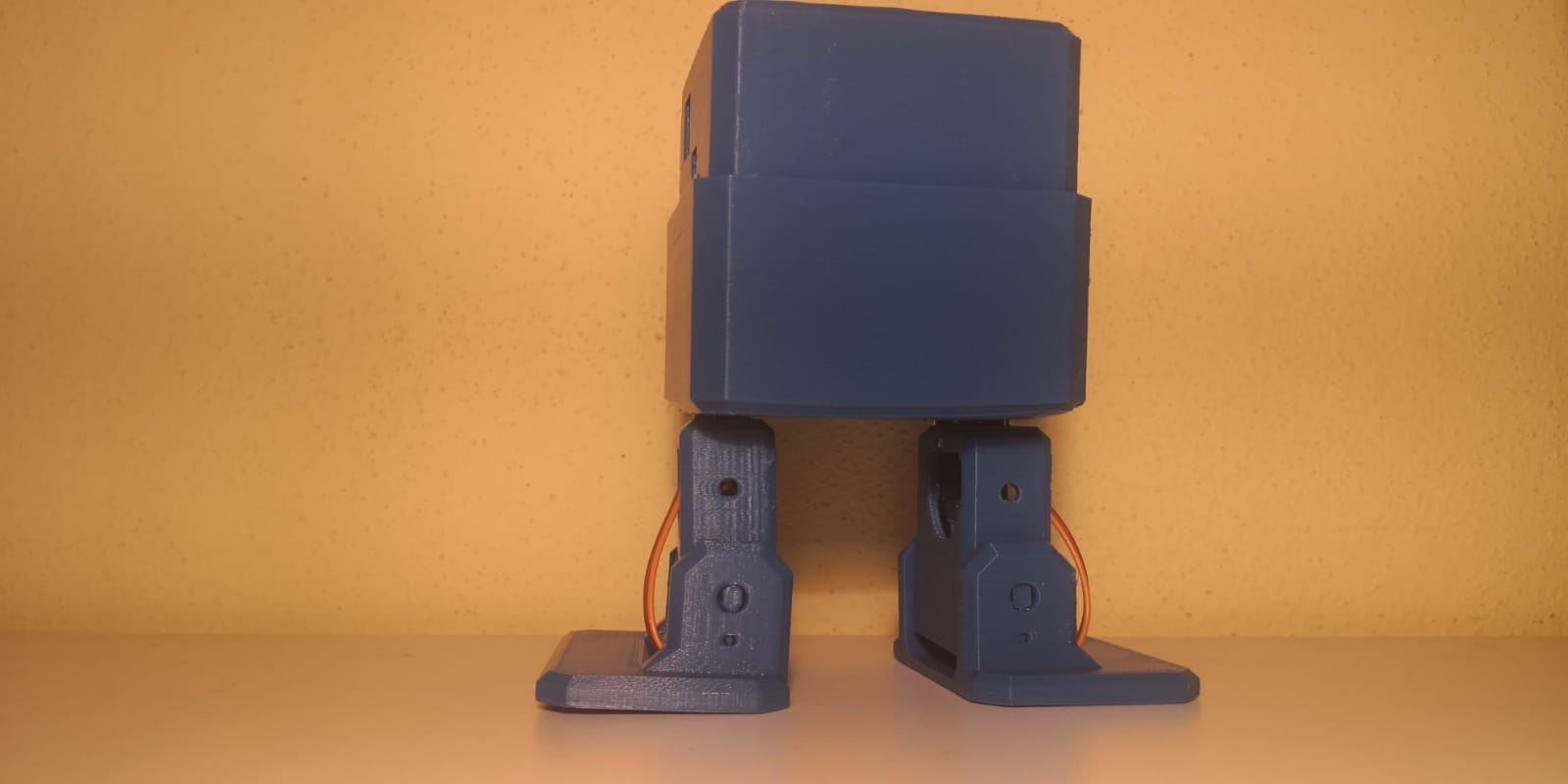
- Gait-Cycle Forensics: The robot utilizes four SG90 micro-servos to achieve locomotion. Two servos manage the "Hips" (lateral displacement), and two manage the "Ankles" (tilt and balance). The movement harmonics require precise phase-shifting: a "Step" is executed by tilting the center of gravity (CoG) onto one foot while the opposite hip rotates forward.
- Iterative Balance Diagnostics: Stability is maintained through a series of pre-programmed "Balance Curves." The firmware calculates the required servo angles $(q_1, q_2, q_3, q_4)$ to ensure the robot's vertical axis remains within the footprint of the supporting leg, preventing kinetic collapse during transit.
- IR-Protocol command Forensics:
- NEC Protocol Handshaking: The remote control (Arduino Uno) encodes joystick vectors into digital IR frames. These pulses are transmitted via a 38kHz carrier wave. The forensics involves the VS1838B receiver node decoding these pulse-width modulated (PWM) optical bursts back into hexadecimal command-codes (e.g.,
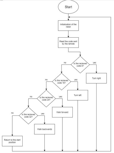
0xFF30CFfor "Forward"). - Signal Integrity Harmonics: To prevent data corruption from ambient IR interference, the system employs a validation logic. The robot will only execute a gait transition if the received code matches a pre-defined bit-mask, ensuring deterministic response to the user's manual inputs.
- NEC Protocol Handshaking: The remote control (Arduino Uno) encodes joystick vectors into digital IR frames. These pulses are transmitted via a 38kHz carrier wave. The forensics involves the VS1838B receiver node decoding these pulse-width modulated (PWM) optical bursts back into hexadecimal command-codes (e.g.,
Engineering & Implementation
- Dual-Node Orchestration:
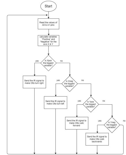
- The Emitter Node: An Arduino Uno monitors the joystick's potentiometric voltage. These analog values are quantized into directional sectors, which trigger the IR transmission loop.
- The Executor Node: An Arduino Nano (mounted on an expansion board for low-impedance signal routing) serves as the "Mind." It manages the high-power servo bus, utilizing an interrupts-driven routine to sample the IR receiver while maintaining the smooth PWM pulses required for jitter-free gait execution.
- Structural Forensics:
- PLA Load-Bearing Diagnostics: The 3D-printed chassis provides the structural rigidity necessary for bipedal stability. Field tests indicate that the servo mounting tolerances must be within 0.1mm to avoid misalignment in the walking axis, which would otherwise induce a systemic drift.
The operation of both devices are described in the following flowcharts.
Conclusion
To complete this project we had to deal with many problems and to learn how to solve them (for example, the Elegoo nano board didn’t have integrated connectors so, to make it work properly, we had to solder all the pins). Other than that, we learned also how to work with components and technologies never studied before which was the main goal of the exercise.
Otto-Link demonstrates the successful integration of Optical Telemetry and Kinematic Control. By mastering IR-Protocol Forensics and Mechatronic Gait Harmonics, momograma has created a resilient, interactive bipedal platform that proves the versatility of the Otto open-source ecosystem in advanced educational and engineering contexts.
Kinetic Balance: Mastering bipedal kinematics through infrared forensics.