We all love playing games. To control games we need controllers, usually that is our keyboard + mouse combination, on phone it's gyroscope and also some buttons. I saw some people make gaming steering wheel but one main problem is those are attached to something, which means they are not portable.
My idea was to design a single controller for racing games that will give the steering wheel vibe and will also come with all the buttons I need. But it has to be movable, so that I can take it anywhere and play on the go. As it is homemade, I can always customize it, reprogram it to configure for any games. See the video for demonstration and build tutorial -
Let's make it guys!
Parts We Need
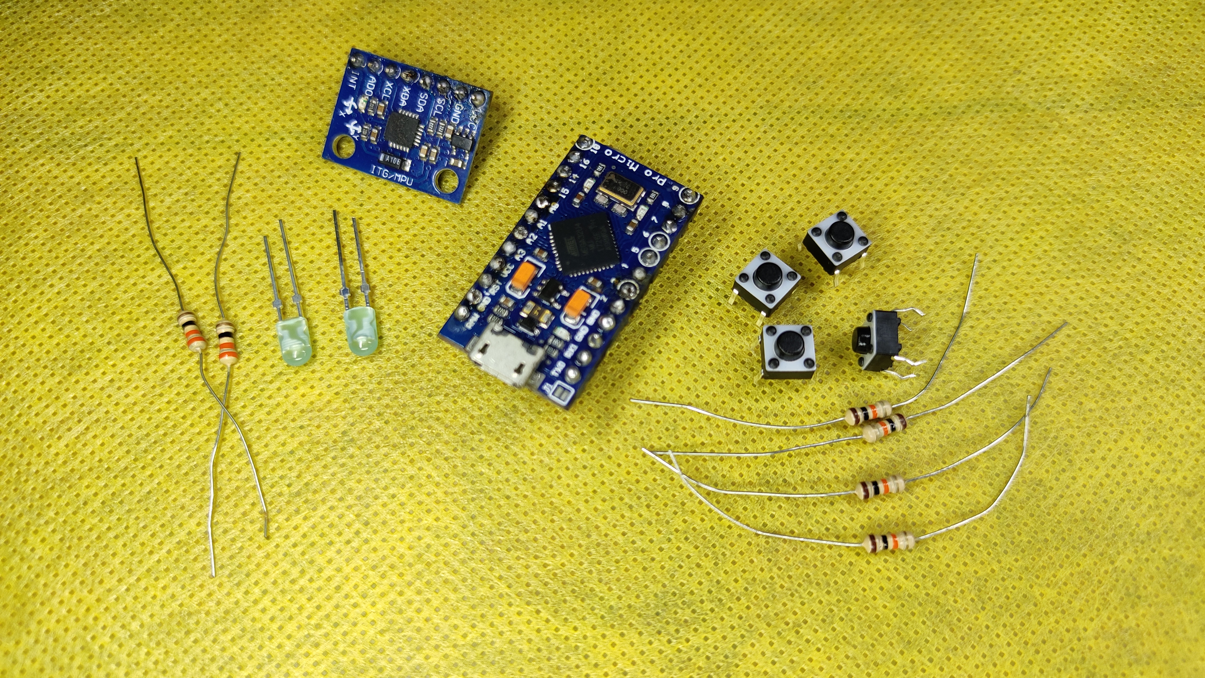
The components are minimal, you can find them at nearest hobby store at a very cheap price
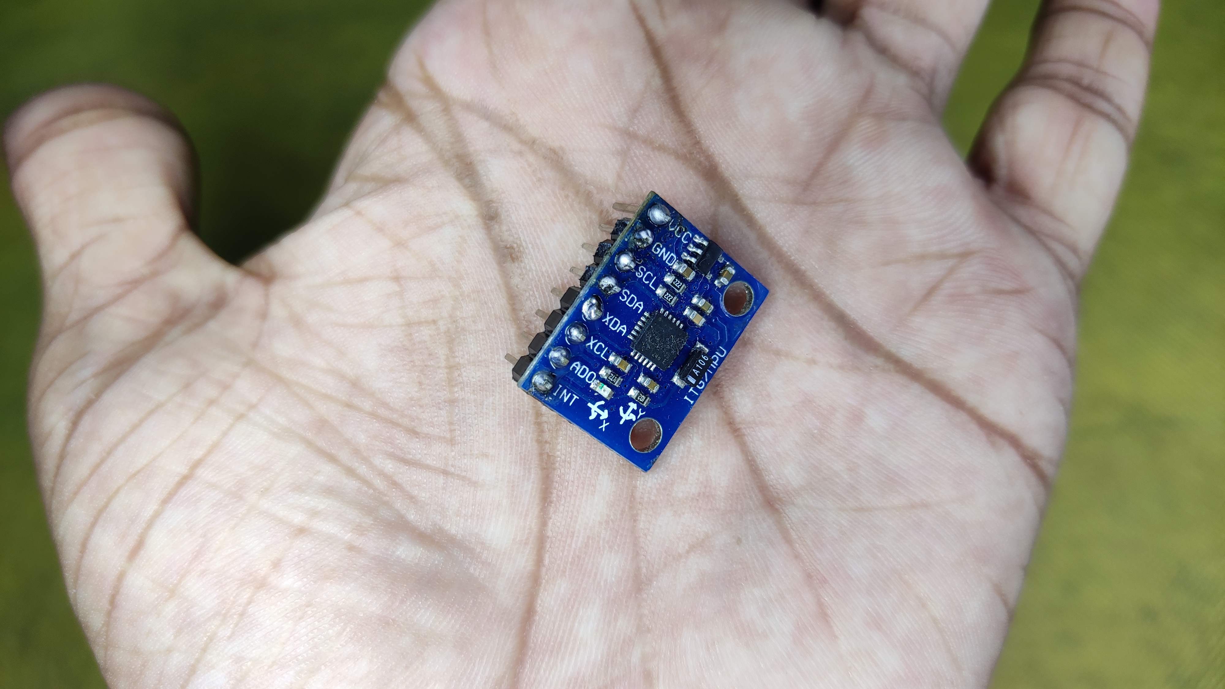
- IMU 6050 - 1x
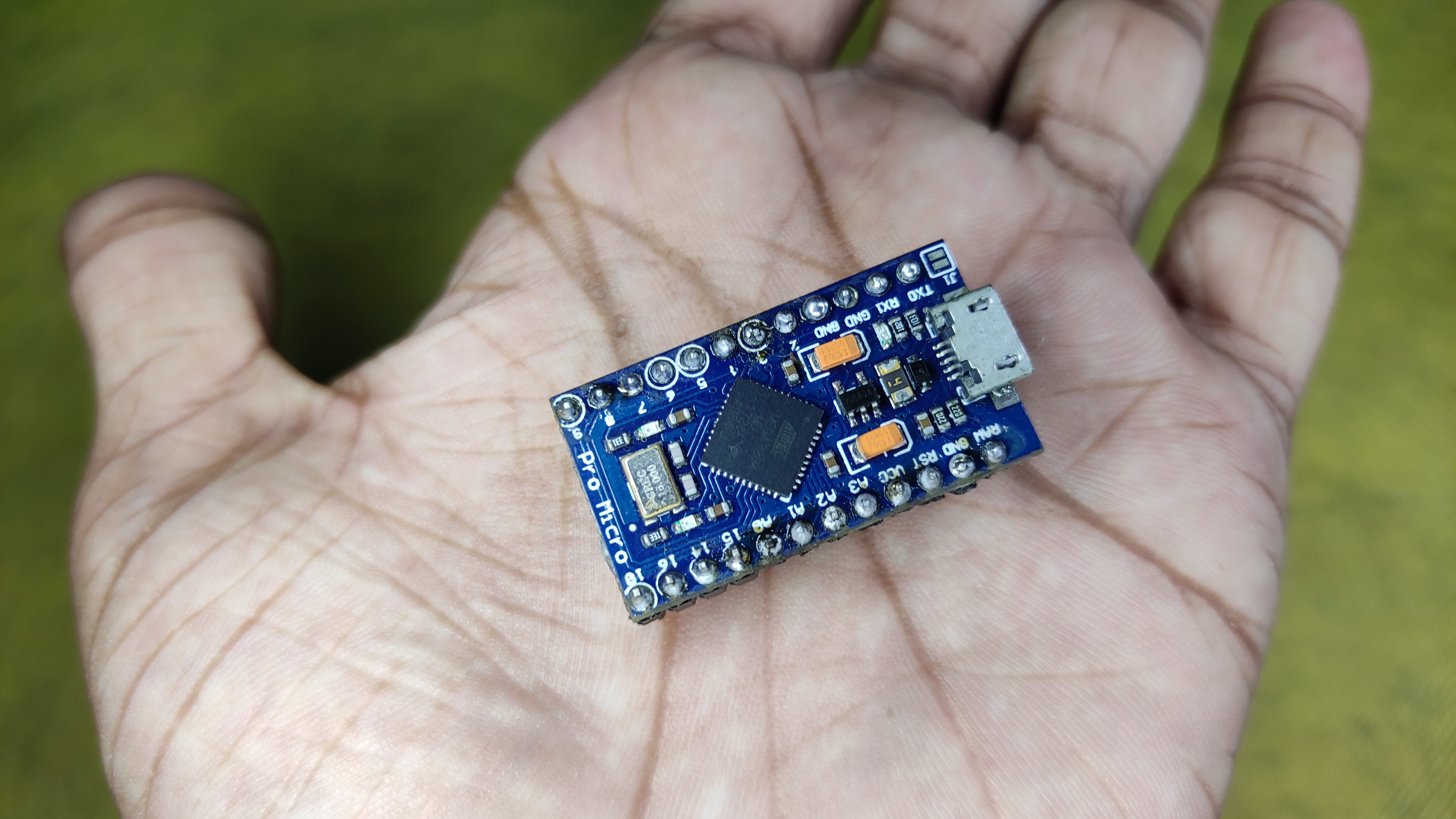
- Arduino Pro Micro - 1x
- Small LED - 2x
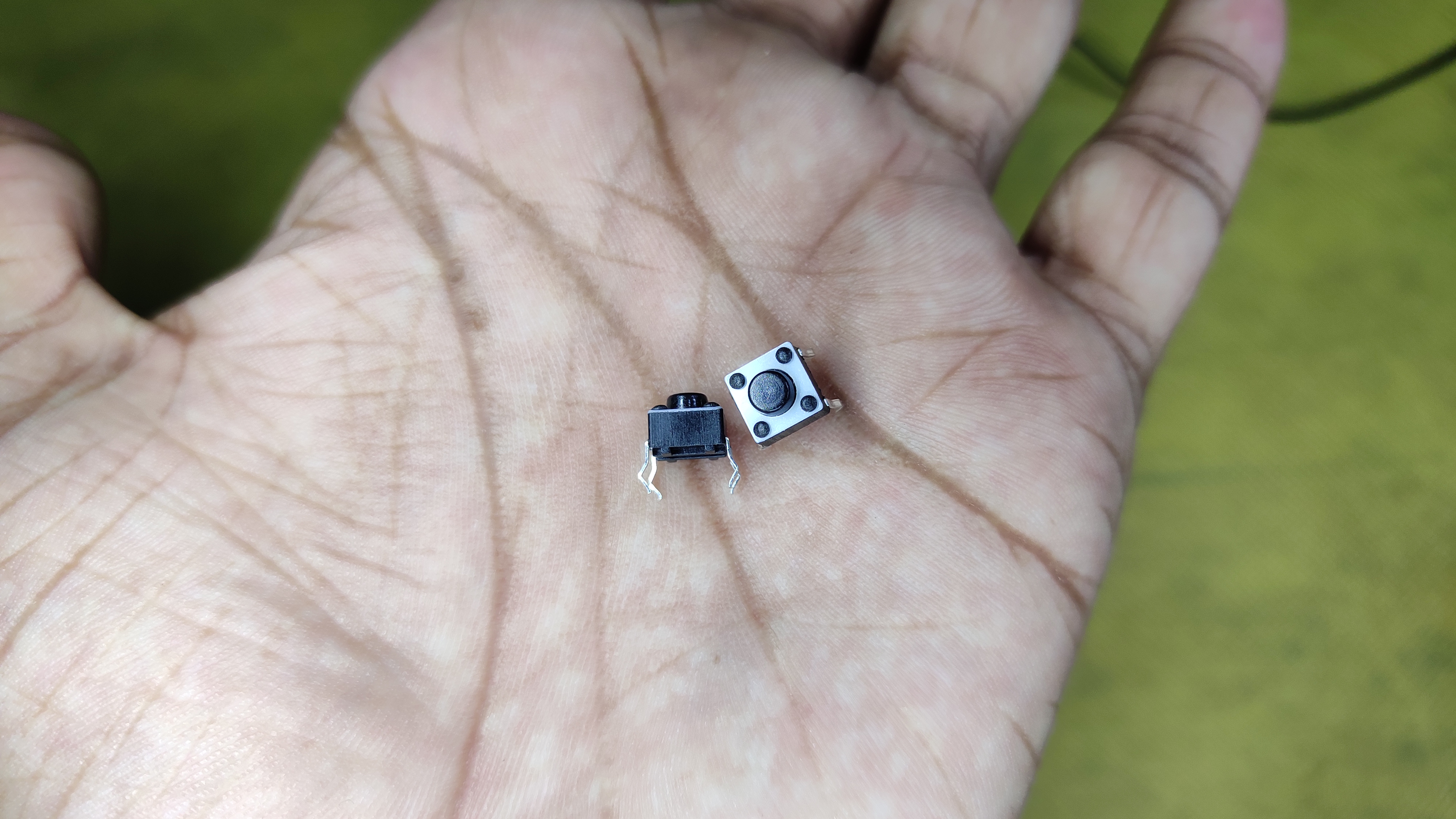
- Mini Push Button - 4x
- 10k Resistor - 4x (For buttons)
- 330r Resistor - 2x (For led's)
Those are the primary components, for soldering things in place you may need (optional):
- Female Header
- Male Header
- Soldering Wire
And one micro USB cable to connect the board to pc an upload program, and for later purpose too.
How Will It Work?
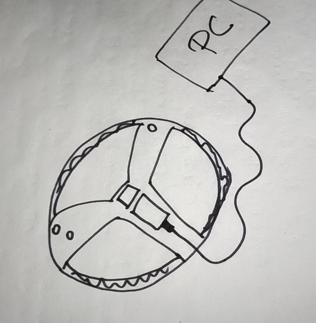
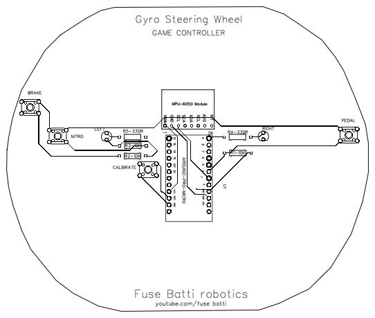
Although that looks like a baby's drawing, that's actually my design! Look doesn't matter as long as it is functional, right? Jokes apart, lets get and idea on how the whole system will work.
The controller will will work like our pc's keyboard and mouse, pressing forward, left right etc. I used Arduino pro micro for that. To get the steer wheel vibe without connecting to any potentiometer I used IMU6050 (Inertia Measurement Unit) to measure Y axis data, that will point out the tilting. And some buttons for pedal, brake, nitro etc.
I targeted Beach Buggy game's pc's version, it's light weight and runs on simple pc's too. To customize the controller with the game what is does is -
- Auto accelerator is on,
- For left right tilt presses - left_arrow, right_arrow
- For power/boost presses - 'z'
- For Character Power presses - 'A'
The whole system is going to be powered from a USB cable that plugs into arduino and goes to all other components. This makes the design more reliable and super cool.
Circuit Diagram
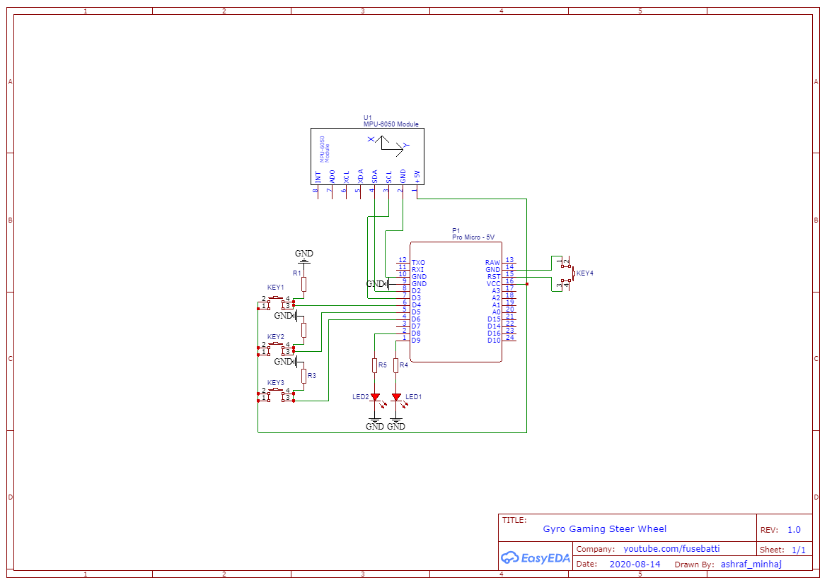
The circuit diagram is simple and easy. I used EasyEDA online editor. One advantage of this system is I don't need to install anything on my pc, thus it doesn't put that much pressure on pc.
The IMU talks to Arduino using I2c protocol and that's basically it.
Drag and drop things from left menu, find the components in the library section. If you use any components make sure it has prints (white masking image will be shown) otherwise it will be a disaster. Connect everything in place and double check. Those are tips for you guys, I already have made the design, you can see that (Image).
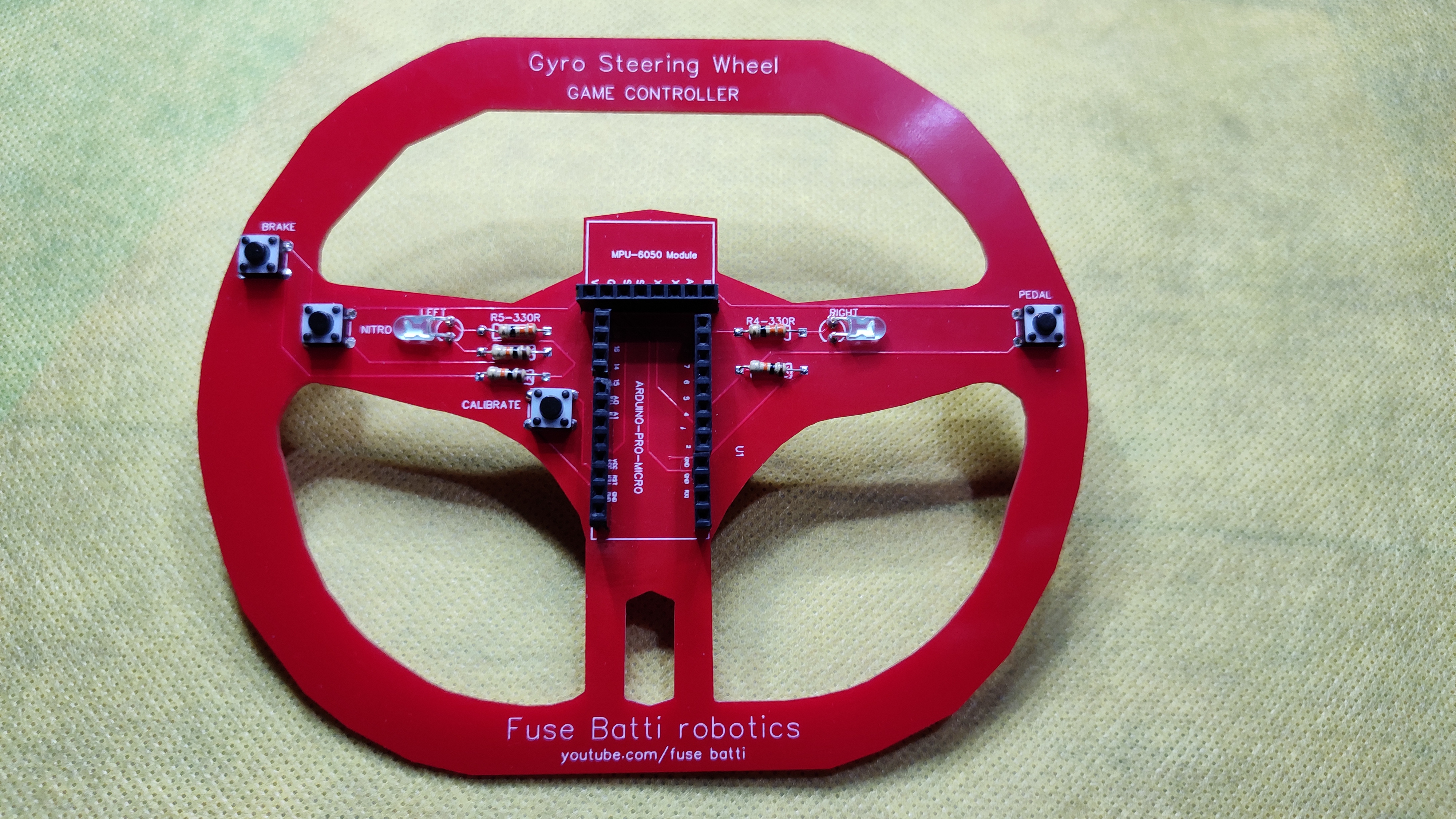
Design and Make PCB
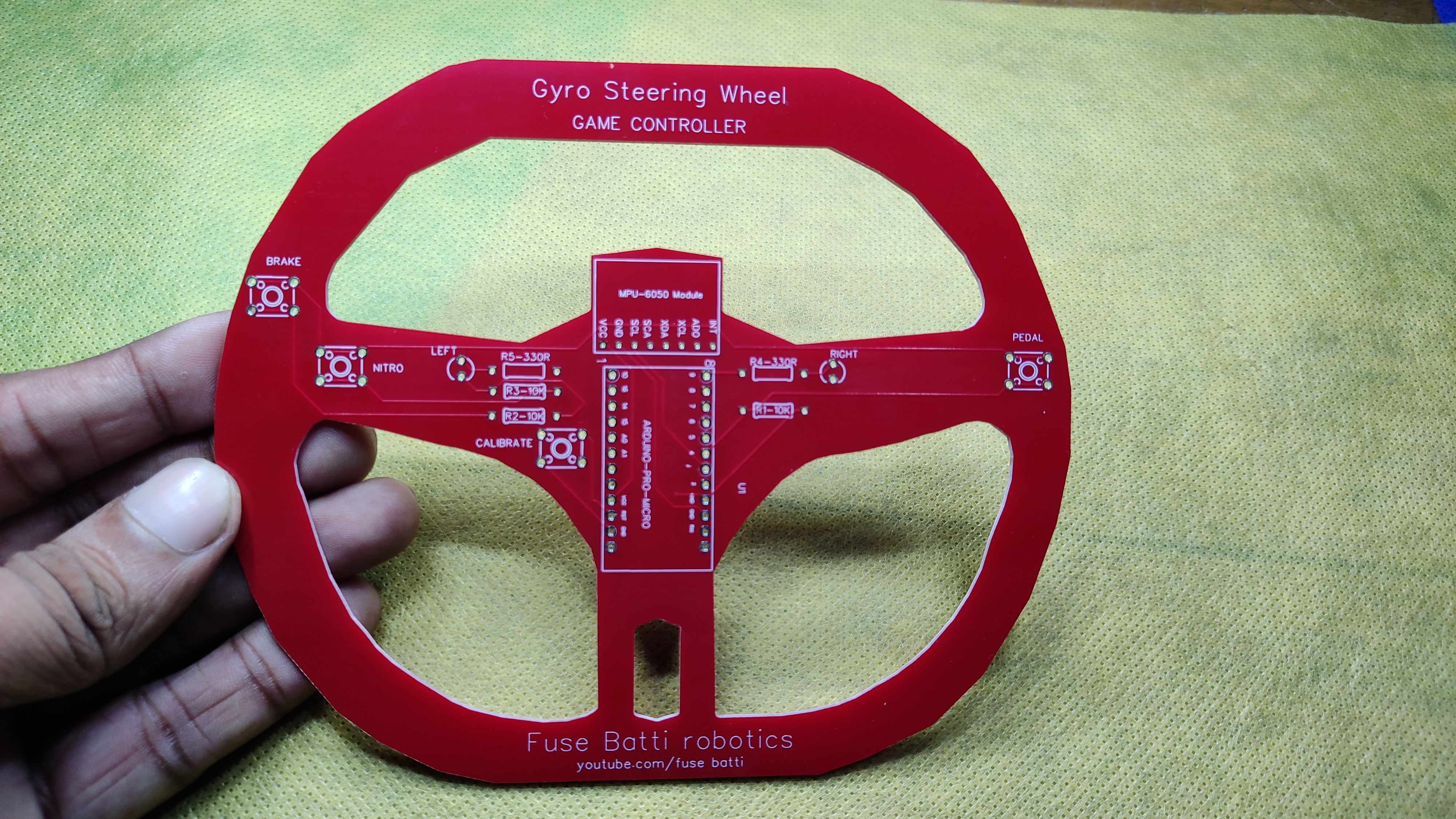
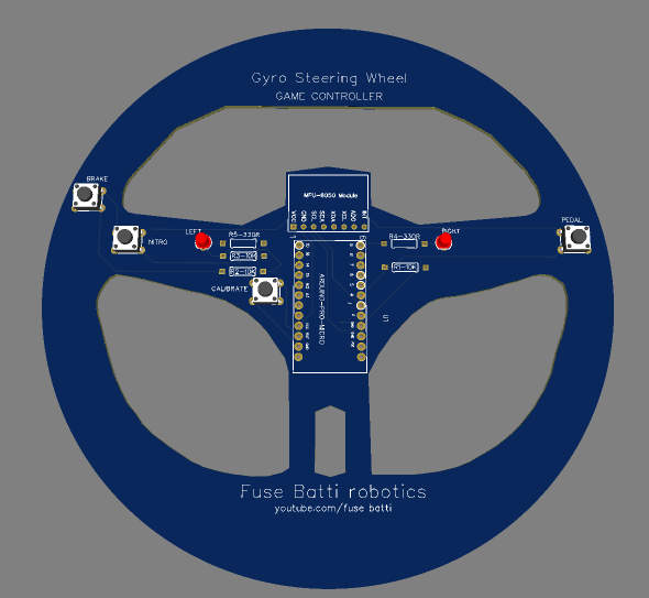

PCB making is super easy, when it comes to custom shape - in my case I wanted it to look like a steering wheel - it becomes tricky. I used the wheel on the 2nd image (without background) as a reference and drew all the lines by hand. Man, this takes everything out of you. I used easyEDA here too.
Okay once done I removed the image and made everything as PCB border. That gave me the shape. Then I placed things in place and made the PCB.
One thing to remember, only one 5v source powers the whole system. So current could be an issue here. That's why I used track width = 0.300 mm. It can pass 1A current easily. After I was satisfied, I exported the pcb gerber file to my pc.
For printing the PCB I used PCBWay service. From there I could print 10 two-layer PCB by only 5$! Which is very very cheap. I used pcb-instant-quote which is a smart system to do everything automatically. I uploaded the gerber file and the system detected layer information, masks everything instantly.
It took 3 days to reach the pcb's from China to Bangladesh of which I had no idea, that's insanely faster than I could imagine. The pcb's look great. All the traces, the masking looks great. I can't believe how they can deliver such quality product in this price range. The finish looks wowsome. The shiny glassy look takes the pcb to another level. I designed them but you know what? The pcb's are inspected by PCBWay's engineering team to deliver me a better product. I am amazed at their service.
PCBWay also sponsors student projects, if you think you have a great idea and need help you can contact them.
Enough talking, now let's solder things.
Get the pcb from here.
Solder Things in Place
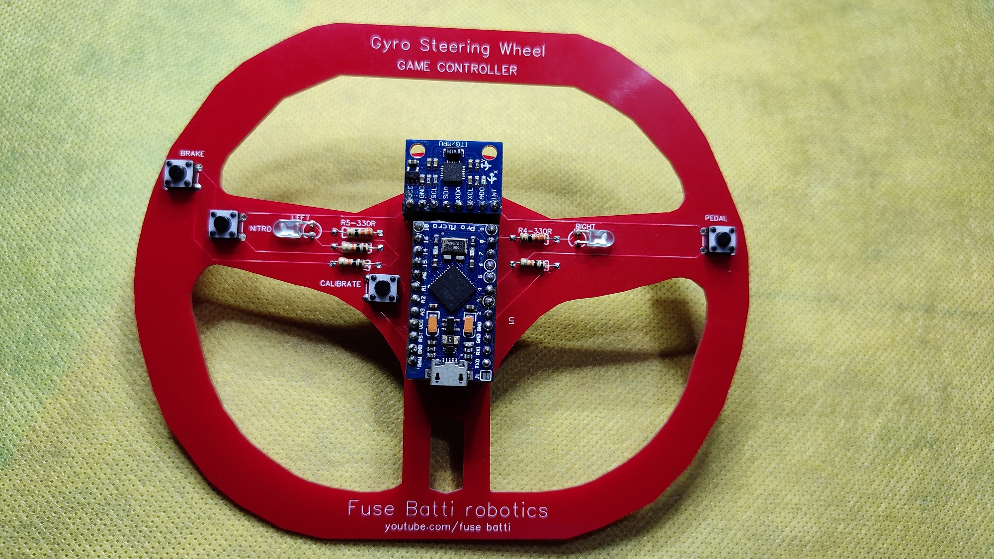
This is a straight forward process, put things in place and solder. Please be careful, do not inhale the fume that comes from the soldering iron. I used optional components (female headers) as I like my devices as - PLUG n Play. Because if one component damages I can easily replace it.
I saw PCB's bend a little after soldering (due to the massive heat of soldering iron) but this PCB stood in place. Thanks PCBWay.
Programming the Board
Now it is time to upload code. The program is written in Arduino code which is C++ (kind of yes).
You can download the full code from here or copy from below, Although I prefer to download from github as code doesn't break that way.
At first I imported keyboard library, then defined button and led pins. In the setup section I set things up, this section runs only once. Inside the loop (which runs till the eternity) I check for button press, if pedal button is pressed then it it checks for IMU (Y position) - tilt- movement and presses left right accordingly. If the brake button is pressed it presses 'down arrow' button, if nitro - 'z', if nitro is pressed twice 'A'. The two led's indicate left right movement so that while looking at the screen you can have a sense of left-right trigger.
As I have used arduino, I can anytime customize it according to my need, for any games.
Technical Implementation Details
The project is a rigorous implementation of Inertial HMI Orchestration and Human Interface Device (HID) Diagnostics. It bridges the gap between traditional stationary steering wheels and portable gaming peripherals by utilizing a 6-axis IMU to translate physical rotation into digital keystroke harmonics.
6-Axis IMU & Orientation Harmonics: The system utilizes the MPU-6050's 3-axis accelerometer to identify the gravitational vector relative to the steering wheel's home-axis. It polls the ACCEL_YOUT registers at high frequency to detect lateral tilt. A THRESHOLD filter (±4000 raw units) is applied to distinguish between intentional steering maneuvers and parasitic vibrational noise, ensuring a stable "Neutral" state. Data ingestion is managed via the I2C protocol, involving direct register manipulation of the power-management (0x6B) and accelerometer-data (0x3B-0x40) blocks to ensure temporal consistency and minimize input-lag.
USB-HID Stack & Logic Diagnostics: Utilizing the ATmega32U4's native USB-HID capabilities and the Keyboard.h library, the Arduino translates physical events into virtual keystrokes for a driverless, low-latency experience. Tactile switch-presses are mapped to 'z' (Nitro) and 'A' (Ability) triggers, while the IMU data drives the KEY_LEFT_ARROW and KEY_RIGHT_ARROW commands. The four pushbutton nodes are configured with 10kΩ pull-down resistors to ensure clean logic-state transitions, with diagnostics focusing on the Nitro button's dual-action for differentiating between secondary ability triggers and primary boost states.
Custom PCB Geometry & Signal-Integrity: The PCB features a custom border that replicates a Formula-1 style steering yoke. Trace-routing maintains a 0.3mm track width for the 5V power-rail to ensure that transient vibrations or LED-switching do not induce voltage-droop on the logic core. Dual LEDs provide real-time visual feedback of the steering-vector, synchronized with the active Keyboard.press command.
Calibration & Neutral-Point Forensics: The implementation features a startup indicator_blink() sequence. During this phase, the system effectively "zeroes" the diagnostic frame, inviting the user to hold the wheel in its neutral orientation.
/*** PCB Steer Gaming Wheel ***
 *
 *  Author: Ashraf Minhaj
 *  Mail: ashraf_minhaj@yahoo.com
 *
 *  Licence: Copyright (C) Ashraf Minhaj
 *  GNU General Public License v3.0
 */
#include
#include
// Threshold value for steering
int THRESHOLD = 4000;
// Controller buttons
int brake = 5;
int nitro = 6;
int pedal = 4;
// Indicator LEDs
int left_led = 8;
int right_led = 9;
int x;
int y;
int z;
const int MPU_addr=0x68;  // I2C address of the MPU-6050
void indicator_blink()
{
  // blinks the leds - 5 times
  int i = 0;

  for(i=0; i<5; i++){
    digitalWrite(left_led, HIGH);
    digitalWrite(right_led, HIGH);
    delay(100);
    digitalWrite(left_led, LOW);
    digitalWrite(right_led, LOW);
    delay(100);
  }
}
void setup(){
  // set pin mode and initialize things
  pinMode(brake, INPUT);
  pinMode(nitro, INPUT);
  pinMode(pedal, INPUT);
  pinMode(left_led, OUTPUT);
  pinMode(right_led, OUTPUT);
  Serial.begin(9600);
  Wire.begin();
  Wire.beginTransmission(MPU_addr);
  Wire.write(0x6B);  // PWR_MGMT_1 register
  Wire.write(0);     // set to zero (wakes up the MPU-6050)
  Wire.endTransmission(true);
  indicator_blink();
}
void loop()
{ // Main loop that runs forever
  Wire.beginTransmission(MPU_addr);
  Wire.write(0x3B);  // starting with register 0x3B (ACCEL_XOUT_H)
  Wire.endTransmission(false);
  Wire.requestFrom(MPU_addr, 14, true);  // request a total of 14 registers
  x = Wire.read()<<8|Wire.read();  // 0x3B (ACCEL_XOUT_H) & 0x3C (ACCEL_XOUT_L)
  y = Wire.read()<<8|Wire.read();  // 0x3D (ACCEL_YOUT_H) & 0x3E (ACCEL_YOUT_L)
  z = Wire.read()<<8|Wire.read();  // 0x3F (ACCEL_ZOUT_H) & 0x40 (ACCEL_ZOUT_L)
  if (digitalRead(brake)){
    Keyboard.release(KEY_UP_ARROW);
    Keyboard.press(KEY_DOWN_ARROW);
    //Keyboard.press(217);
  }
  if (digitalRead(nitro)){
    delay(10);
    Keyboard.press('z');
    if (digitalRead(nitro)){
      Keyboard.press('A');
    }
  }
  else if (digitalRead(pedal)){
    Keyboard.release(KEY_DOWN_ARROW);
    Keyboard.press(KEY_UP_ARROW);
    //Keyboard.press(218);
if(y < -THRESHOLD){
      Serial.print("    Left    ");
      Keyboard.release(KEY_RIGHT_ARROW);
      Keyboard.press(KEY_LEFT_ARROW);
      digitalWrite(left_led, HIGH);
  }

else if(y > THRESHOLD){
      Serial.print("    Right    ");
      Keyboard.release(KEY_LEFT_ARROW);
      Keyboard.press(KEY_RIGHT_ARROW);
      digitalWrite(right_led, HIGH);
  //Keyboard.press(37);
  }
 else{
      Keyboard.releaseAll();
 }

   }
  //Serial.println(y);
  delay(10);
    digitalWrite(left_led, LOW);
    digitalWrite(right_led, LOW);
}
Upload the code from Arduino.ide and two led's that indicate left right tilt will blink five times. Which means the board is ready to go.
Done- Connect and Play
And done! Connect the wheel to pc using a USB cable and play. Customize it according to your