This is an excerpt from a larger project, but the code was fully functional in the original.
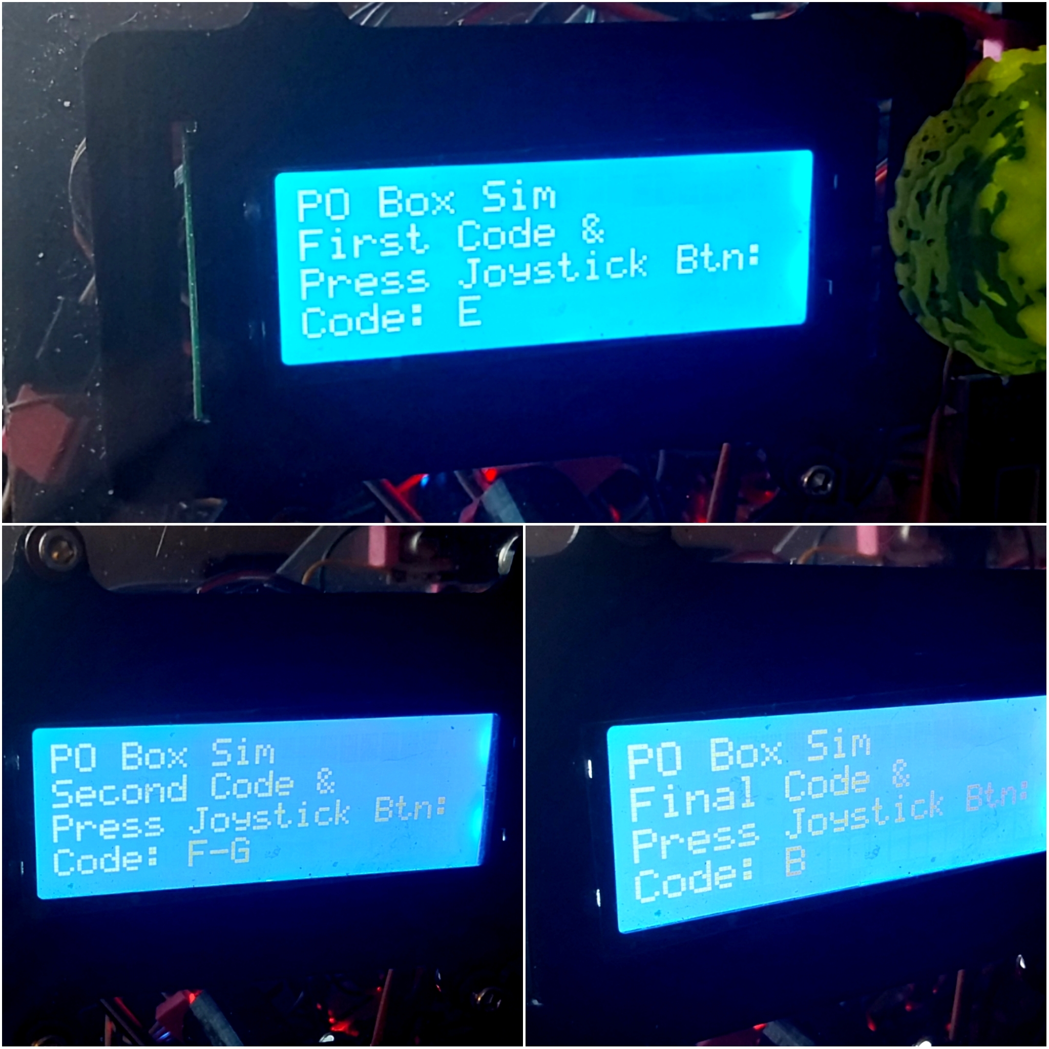
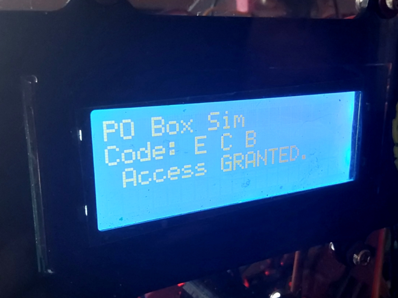
Most entry locks use a keypad for code entry. But if you've ever been to an old post office the Government uses an essentially unpickable lock for the mail. Each has 10 letters, A-J and in-between locations are valid, D-E, J-A, etc. for a total of 20 codes times three steps for 20x20x20 or 8000 permutations.
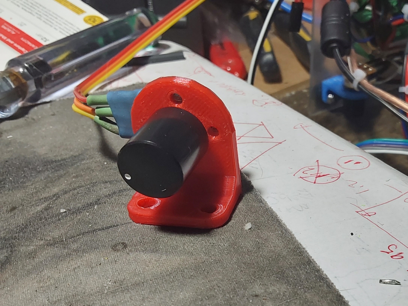
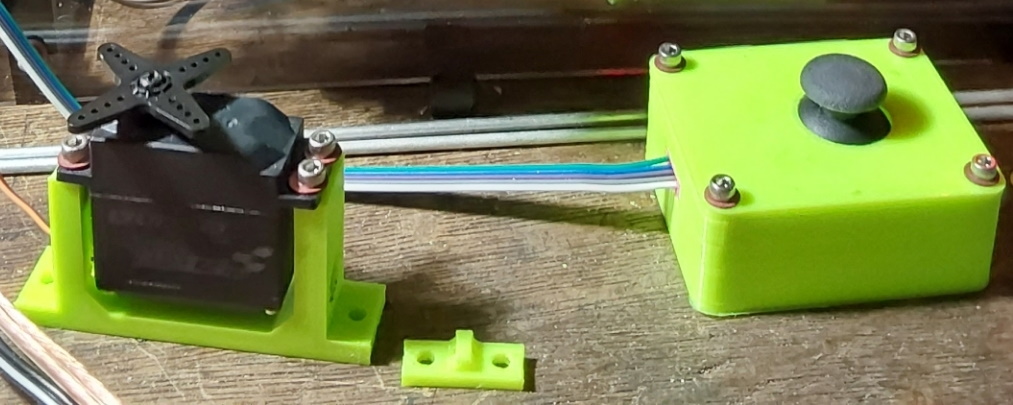
Dialing a combination lock is simulated by using a potentiometer (pot) to enter the key code. The analog input for the pot is read and the 0-1023 input range is mapped to any one of 20 key codes. The Z-axis input from the Joystick (the push button) is used to signal data entry.
The code has three essentially the same code blocks, one for each "digit". These could easily be combined into a series of subs, but that is left as an exercise for the reader.
Once the three key codes have been entered, the entered code is compared to the correct code, and if correct, the servo is rotated thru a specified angle. The angle in this example was determined by direct measurement of the CAD depicting the locking mechanism.
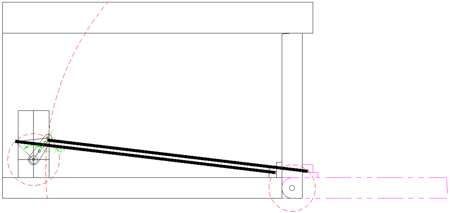
This lock is designed to open a flip up wooden door in a box large enough to hold whatever.
In this example, the servo relocks automatically after a specified period of time.
The system that this was developed on is based on a fully loaded Mega 2560 with multiple 20 x 4 LCD's and almost all D's used - hence the big # on the Z-axis D.
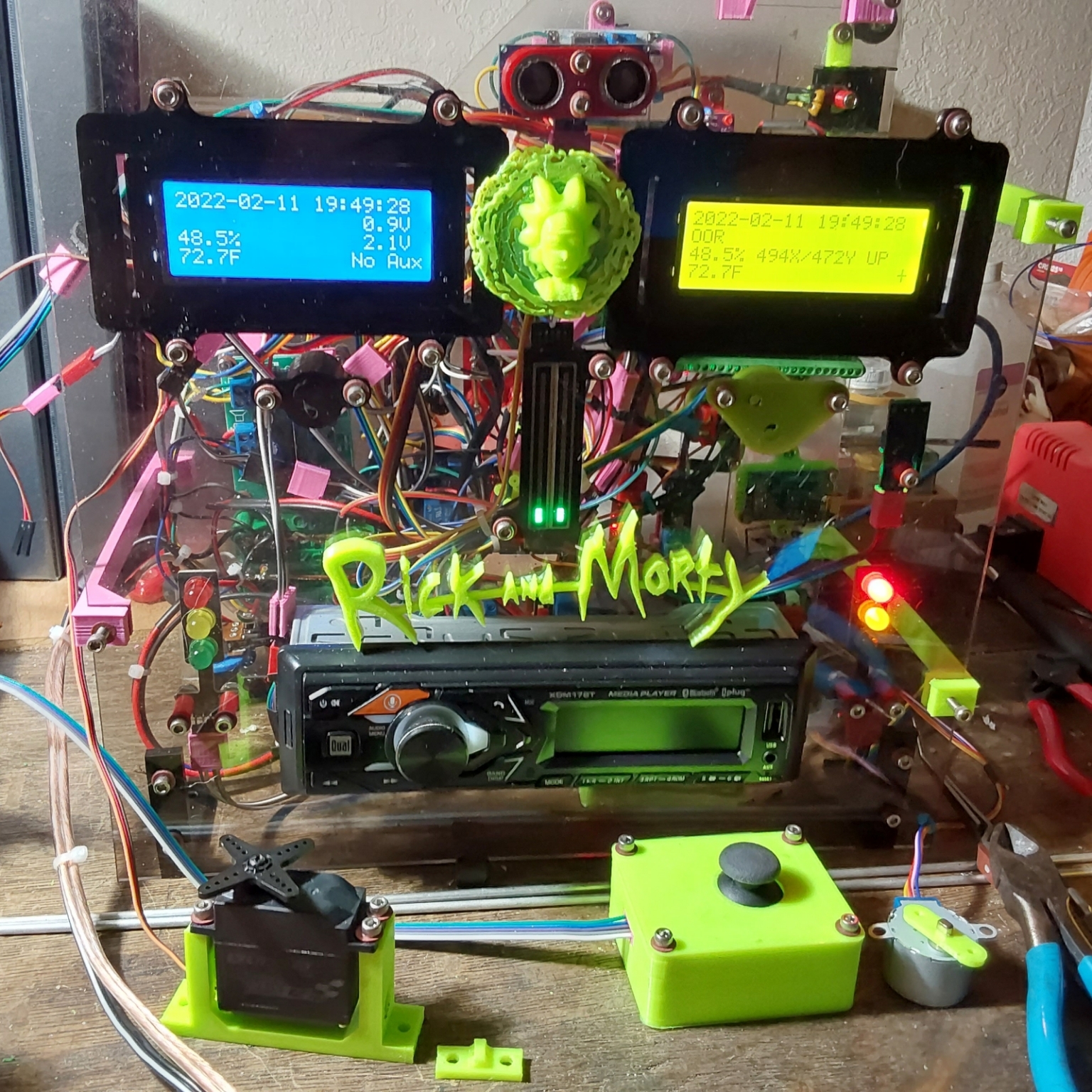
The code is triggered by a push button on the IR remote and there is a LOT of extraneous code for unrelated functions. I have stripped the code down to just the essentials, so the normal SETUP() and LOOP() constructs are omitted, but I hope everything is simple enough to understand.
The servo used is a $20 metal servo instead of the little plastic one that comes with most Arduino starter kits. A bracket for the servo and a mount for the door are 3D printed and the.STL files are included in this project.
EXPANDED TECHNICAL DETAILS
Digital Security for Physical Storage
This project modernizes a vintage PO Box or mini-safe with a secure, digital combination lock mechanism.
- Incremental Entry Logic: The Arduino monitors a Potentiometer or Rotary Encoder. The user "Dials" the numbers to match a preset code (e.g., 10-25-05). The firmware tracks the rotational direction and stopping point to verify the combination.
- Servo Actuation Hub: Upon successful entry, the Arduino rotates a high-torque SG90 or MG995 servo to physically rotate the lock's cam, allowing the door to open.
Security Features
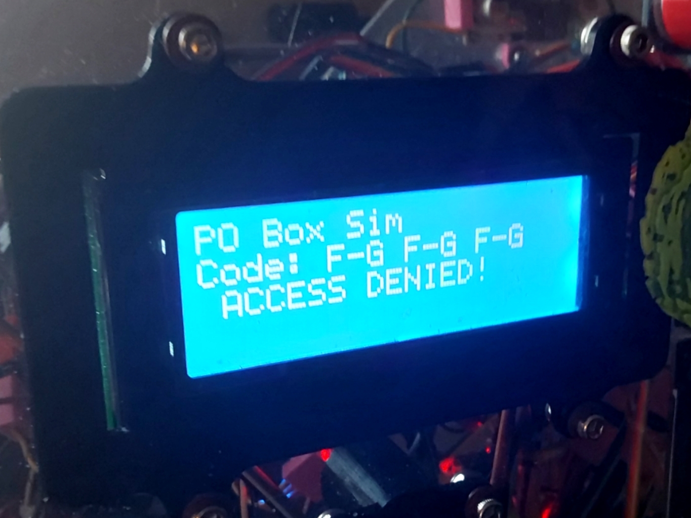
- Tamper Alert: Features an "Anti-Brute Force" delay. If an incorrect combination is entered three times, the Arduino disables the input for 5 minutes and flashes a red "Warning" LED.