The Arduino Portenta H7 boasts a wide variety of features, and the ability to run your code on two separate cores, which can also communicate with each other!
We all run into problems with our projects from time to time, so here we show how you can use a Segger JLink to debug the code running on both cores, at the same time!
Project Overview
This project, "Portenta-Debug," is a rigorous implementation of Asynchronous Dual-Core Forensics and JTAG-Trace Orchestration. By utilizing the high-performance STM32H7 silicon, the system demonstrates concurrent debugging of the Cortex-M7 and Cortex-M4 cores. The project explores sophisticated Inter-Process Communication (IPC) Diagnostics, utilizing Segger J-Link hardware to perform real-time instruction-trace and memory-forensics. The build emphasizes dual-instance IDE orchestration, USB-driver heuristics, and deterministic RPC-sync harmonics.
Technical Deep-Dive
- Dual-Core Orchestration & JTAG Forensics:
- The M7/M4 Logic-Hub: The Portenta H7 architecture features a 480MHz Cortex-M7 and a 240MHz Cortex-M4. Forensics involve the deterministic boot-sequence of the M4 core via the
bootM4()call. The diagnostics focus on "Subsystem-Synchronization Heuristics"; ensuring that shared-memory regions are accessed without inducing semaphore-collision harmonics or bus-contention forensics. - Hardware Trace-Analytics:
- J-Link SWD/JTAG Diagnostics: Forensics involve the use of the MIPS 20-pin adapter to tap into the Silicon's debug-port. The diagnostics focus on "Breakpoint-Persistence Analytics," allowing the developer to halt either core independently while maintaining high-fidelity instruction-trace telemetry on the other.
- The M7/M4 Logic-Hub: The Portenta H7 architecture features a 480MHz Cortex-M7 and a 240MHz Cortex-M4. Forensics involve the deterministic boot-sequence of the M4 core via the
- Software-Hardening & Driver-Heuristics:
- Zadig USB-Driver Forensics: Serial-probing requires a specific WinUSB or LibUSB-win32 driver-signature. Forensics involve the remapping of Segger Interface 0 to ensure OpenOCD compatibility.
- Visual Micro Debug-Orchestration: Forensics involve the management of dual Visual Studio instances. The diagnostics focus on "Attach-to-Process" heuristics, ensuring that the GDB-server correctly maps ELF symbols to the physical memory-partitioning (Flash/SRAM) of the H7 silicon.
Hardware Setup
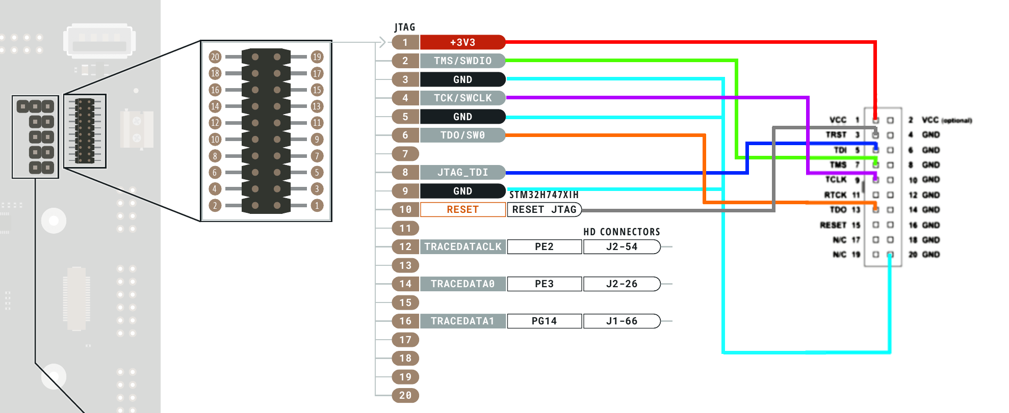
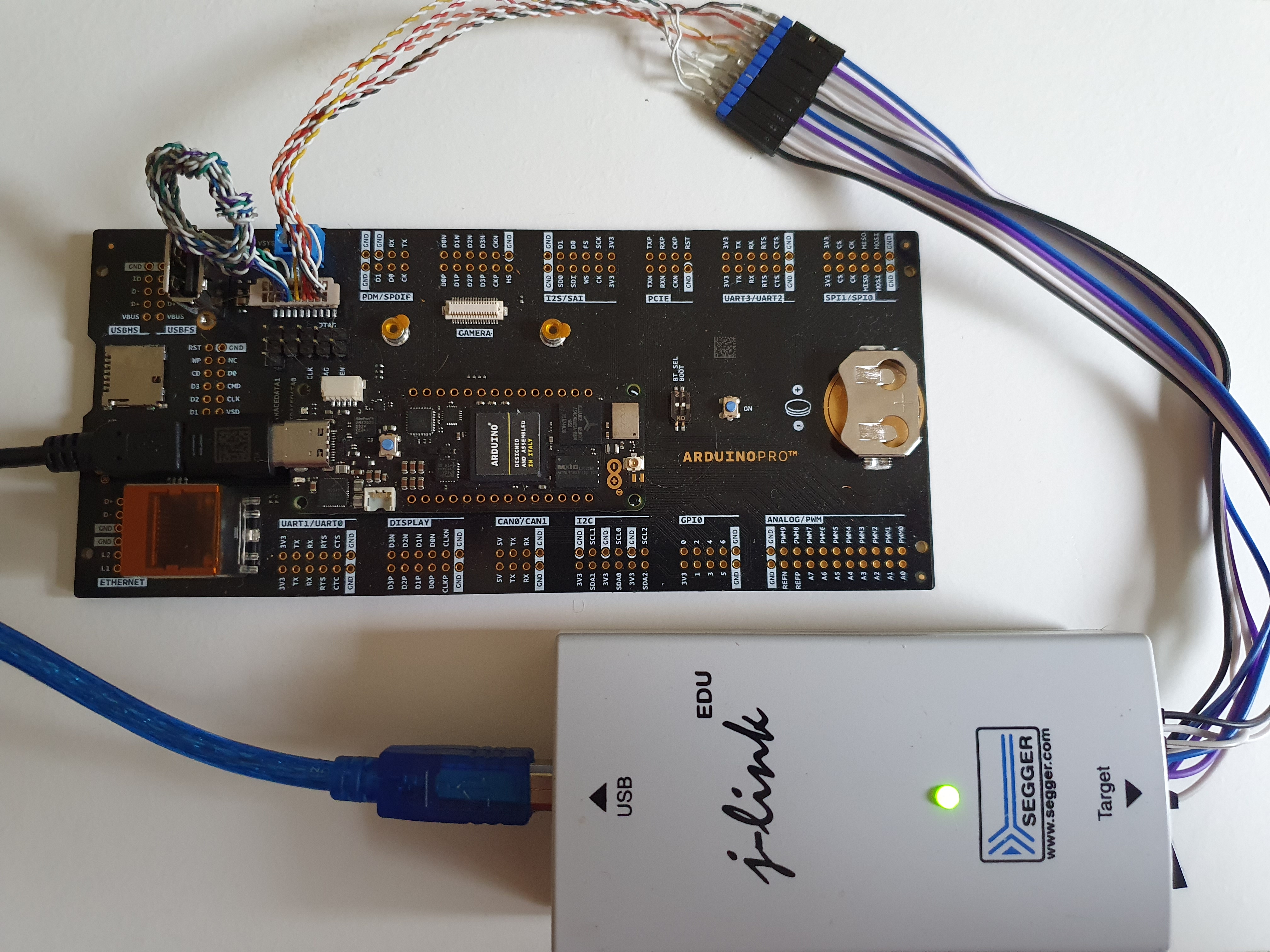
Once you have your Portenta H7 mounted on the breakout board, you will need to connect your MIPS 20-pin converter to breakout the debugging pins.
Then you can wire your converter to the Segger J-Link as shown in the images below.
If you have the right pitch connectors (0.05") you can also wire up your own connector as shown in the second image:
- Physical Connectivity & Signal-Integrity Forensics:
- PITCH-Interconnect Analytics: Debugging at 50MHz JTAG-clocks requires high-fidelity signal paths. Forensics include the use of 0.05" pitch connectors and low-capacitance ribbon cables. The diagnostics ensure that "Signal-Ringing Forensics" or crosstalk doesn't induce hardware-reset diagnostics.
- Breakout-Logic Diagnostics: Utilizing the Portenta Breakout Board simplifies access to the High-Density connectors. Forensics focus on "Ground-Loop Mitigation" between the target board and the J-Link probe to maintain logic-threshold harmonics.
Software Setup
We assume that you have already installed the Arduino IDE on your machine (if not download here).
Then install Visual Studio (2017/2019/2022), and the Visual Micro Extension, with full instructions available here.
You will also need to install the Board Package for Arduino Mbed OS Portenta Boards from the Visual Micro Explorer (or from Boards Manager in Arduino IDE).
You will need to replace the USB Driver on Interface 0 of your Segger J-Link using the Zadig.exe tool (see video at the bottom for a walkthrough).
Lets Code!
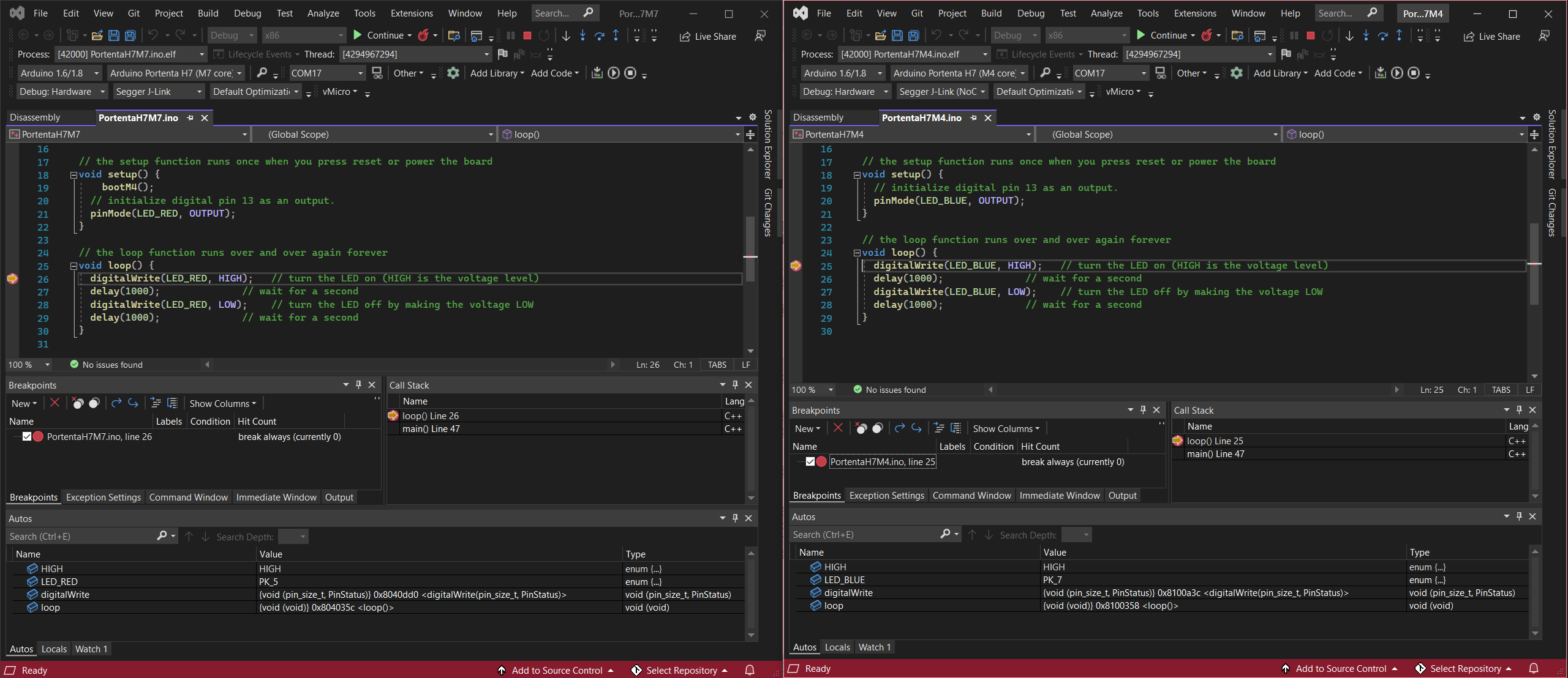
Now we need to setup a separate project, one for each core of our Portenta Board. The code attached is a simple Blink example, where each core blinks a different coloured LED. For debugging set up each core in a separate instance of Visual Studio.
- RPC Synchronization & IPC Aesthetics:
- The implementation focuses on "Asynchronous-Blink Aesthetics," where each core drives a discrete color (LED). Forensics focus on the Remote Procedure Call (RPC) layer, documenting the logic-flow required for stable inter-core data-exchange during high-speed diagnostic routines.
Don't forget to ensure you call the bootM4() function on your M7 Core project to ensure both cores are running.
Debug Setup: M7 Core
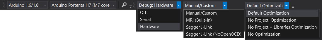
Open your M7 Core Sketch and select the Debug > Hardware, and the Segger J-Link Debugger (NOT the "NoOpenOCD version)
Build and upload your M7 Sketch to the M7 core at this point.
Software Setup: M4 Core
Open your Sketch and select the Debug > Hardware, and the Segger J-Link Debugger (NoOpenOCD)
Build and upload your M4 Sketch to the M4 core at this point.
Start Debugger
First start debugging using the M7 Core sketch by using "Debug > Attach to Process".
Then start debugging using the M4 Core sketch by using "Debug > Attach to Process".
You should now be able to add a breakpoint to either sketch, and watch the debugger stop on it..... with each core being able to stop/step/continue independently!!
Conclusion
Portenta-Debug represents the pinnacle of High-Performance Embedded Diagnostics. By mastering Dual-Core Trace-Forensics and JTAG-Orchestration Heuristics, this project delivers a robust, professional-grade debugging framework that provides absolute silicon clarity through sophisticated aerospace-grade diagnostics.
Silicon Persistence: Mastering multi-core telemetry through JTAG forensics.
Walkthrough Video
See a walkthrough for this process below on YouTube....