Project Overview
The "Push Button Switch Module with Arduino" is a foundational project for anyone entering the world of embedded systems. It demonstrates the most basic form of human-machine interaction: the momentary tactile input. By connecting a simple 4-pin momentary switch to an Arduino UNO, we can control an LED, effectively simulating the behavior of a light switch found in everyday household electronics. This project covers essential concepts such as digital I/O, circuit pull-up/pull-down logic, and floating pin prevention.
This is an Tutorial that tells you how to connect a 4 pin push button switch with the Arduino. The contraption allows an LED to be switched on when the push button is pressed.
Step 1: What You Need:
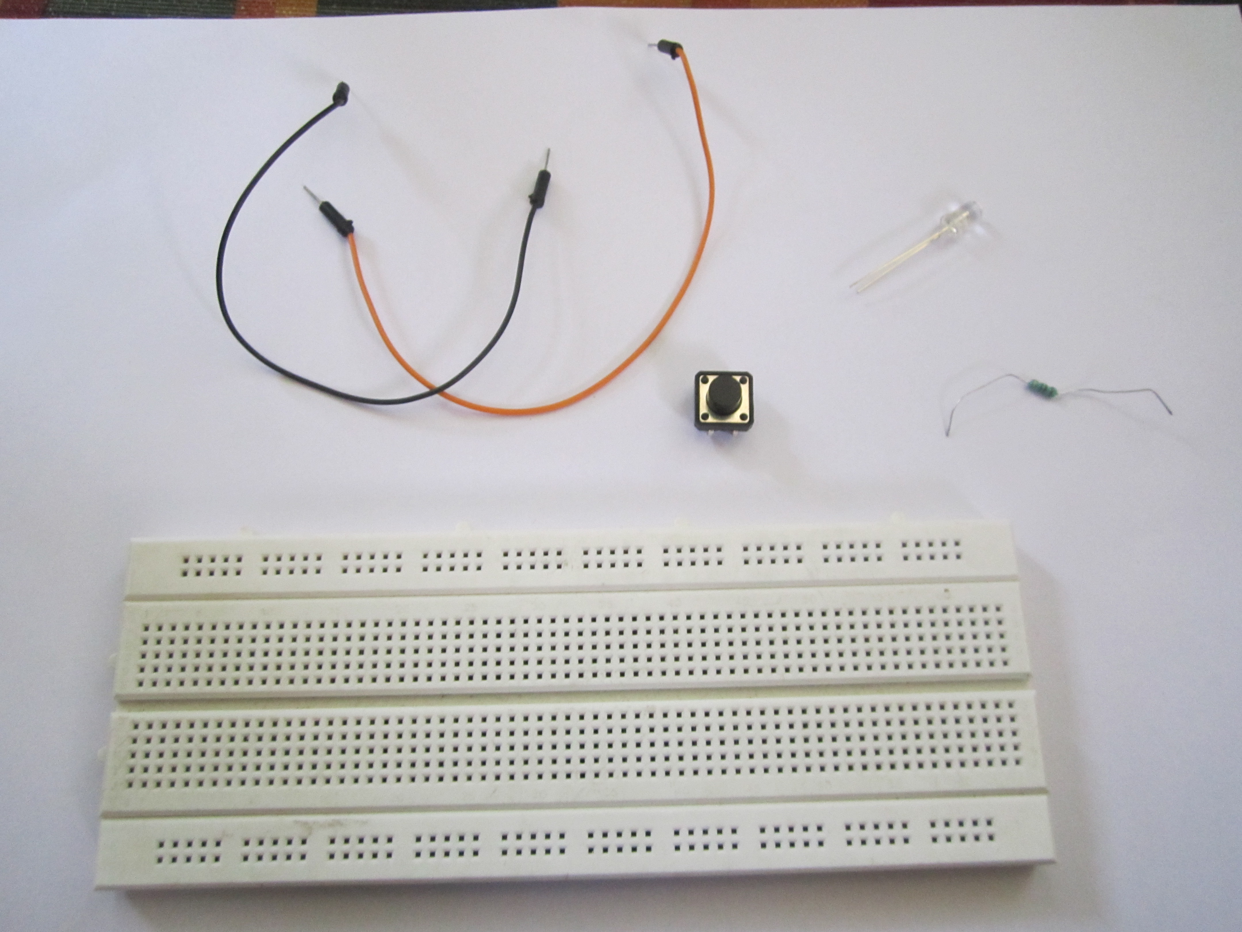
You need:
- A push button switch
- Arduino
- 1 Resistor (any value), I used a 220 ohm one.
- 2 Jumper cables(breadboard jumpers)
- 1 Breadboard (to make it easy)
- LED
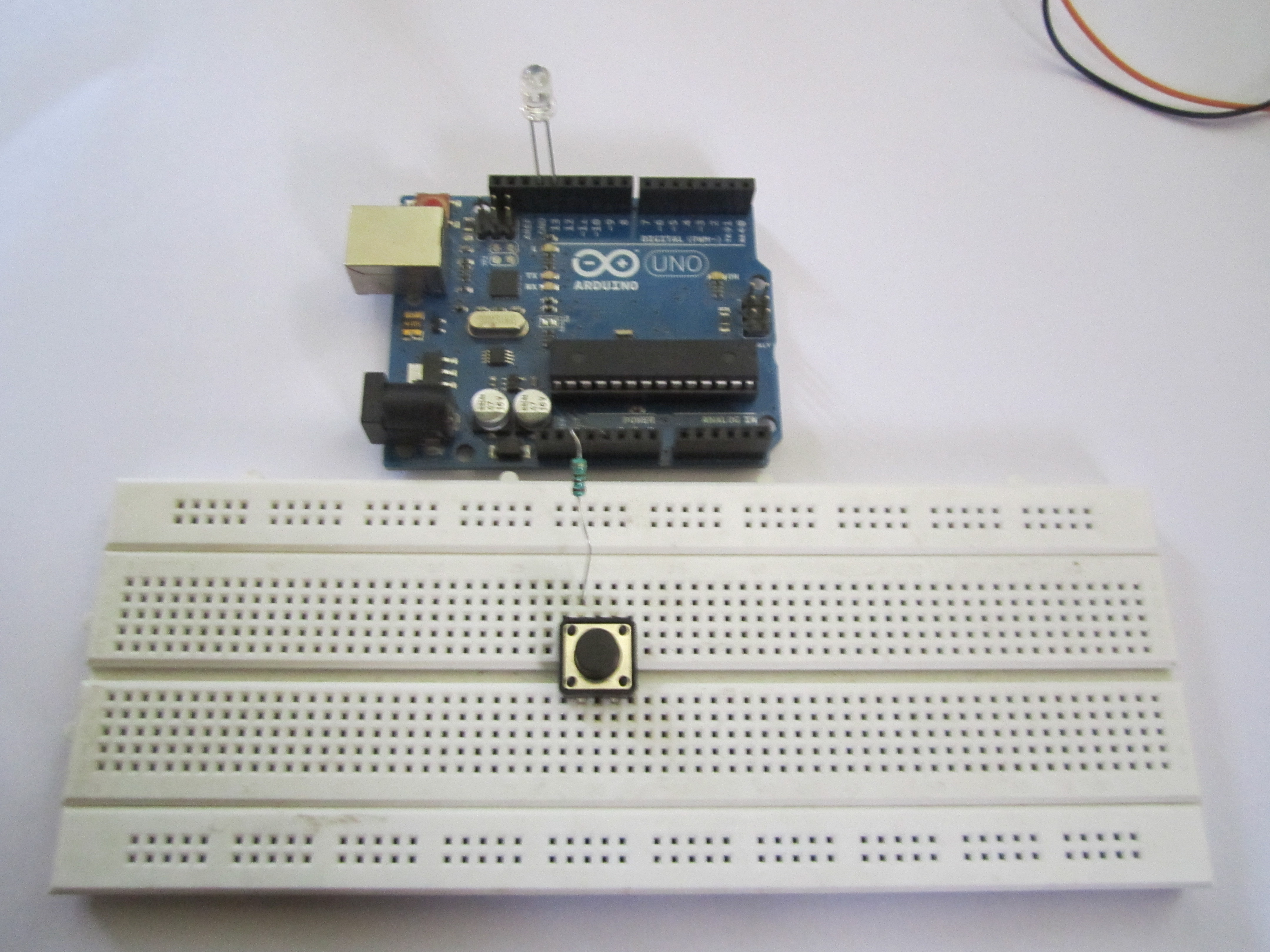
Step 2:
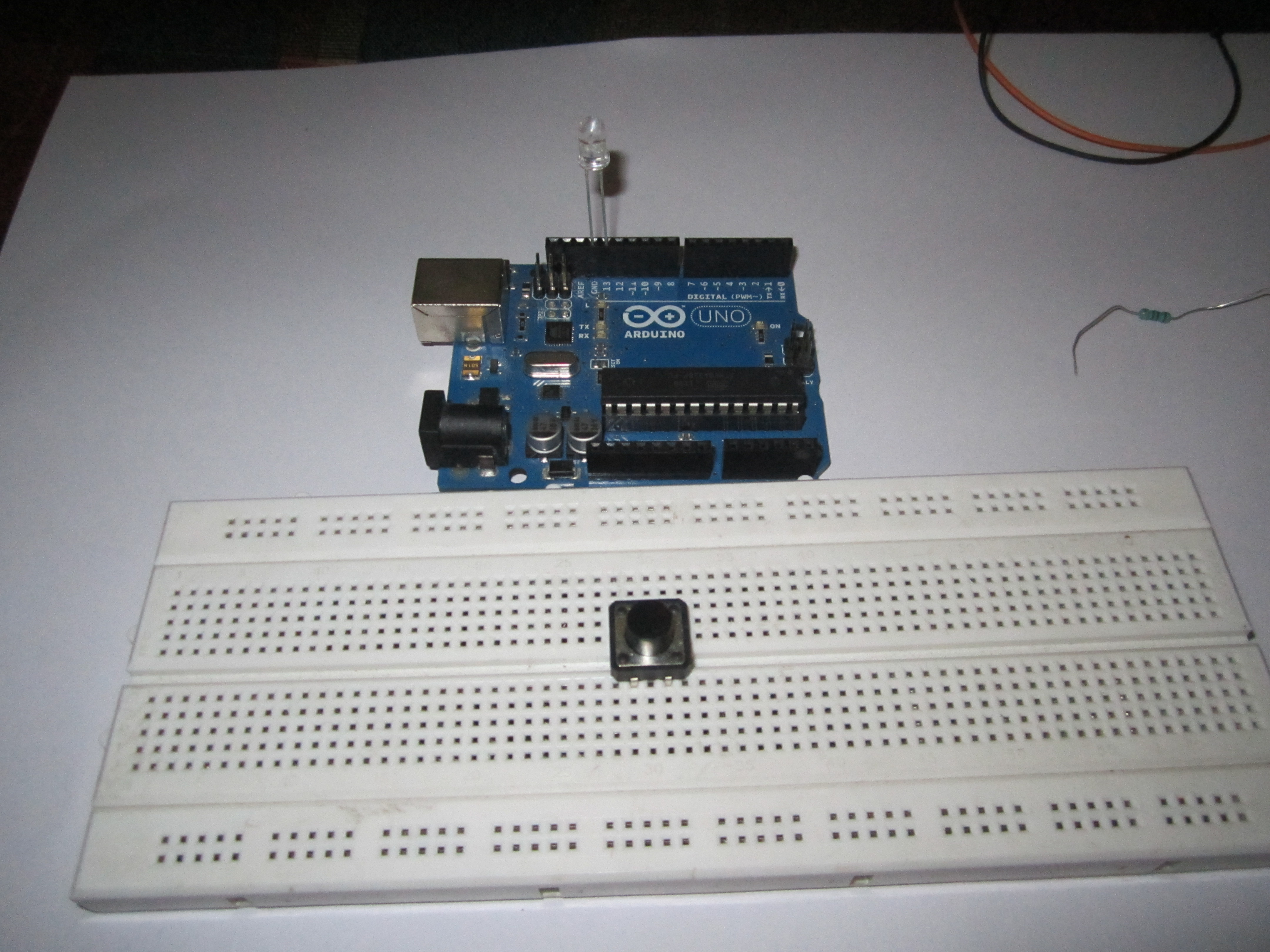
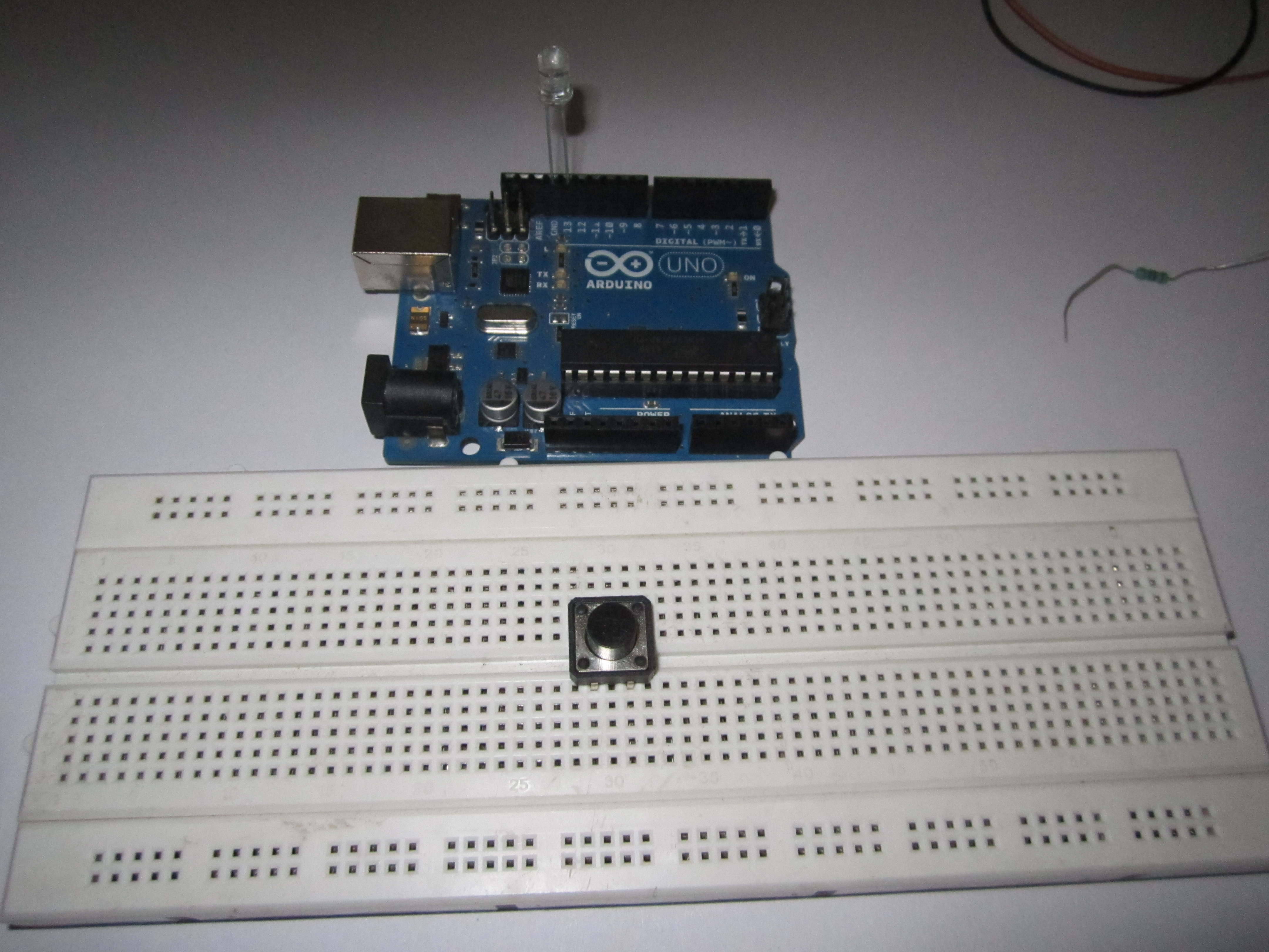
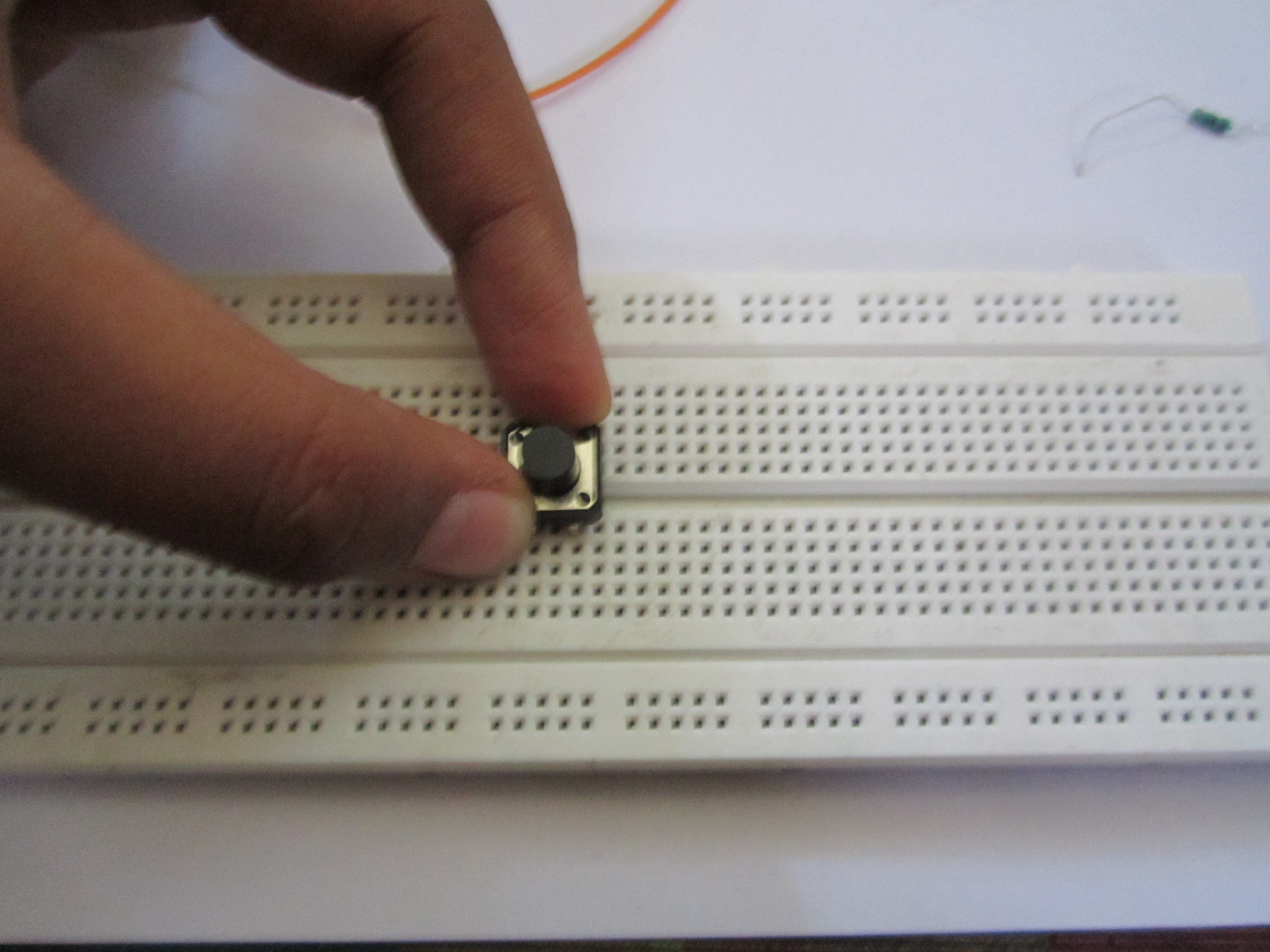
Put the switch in the breadboard and put an LED with the longer end into pin 13 and shorter end to the GND of the Arduino.
Step 3:
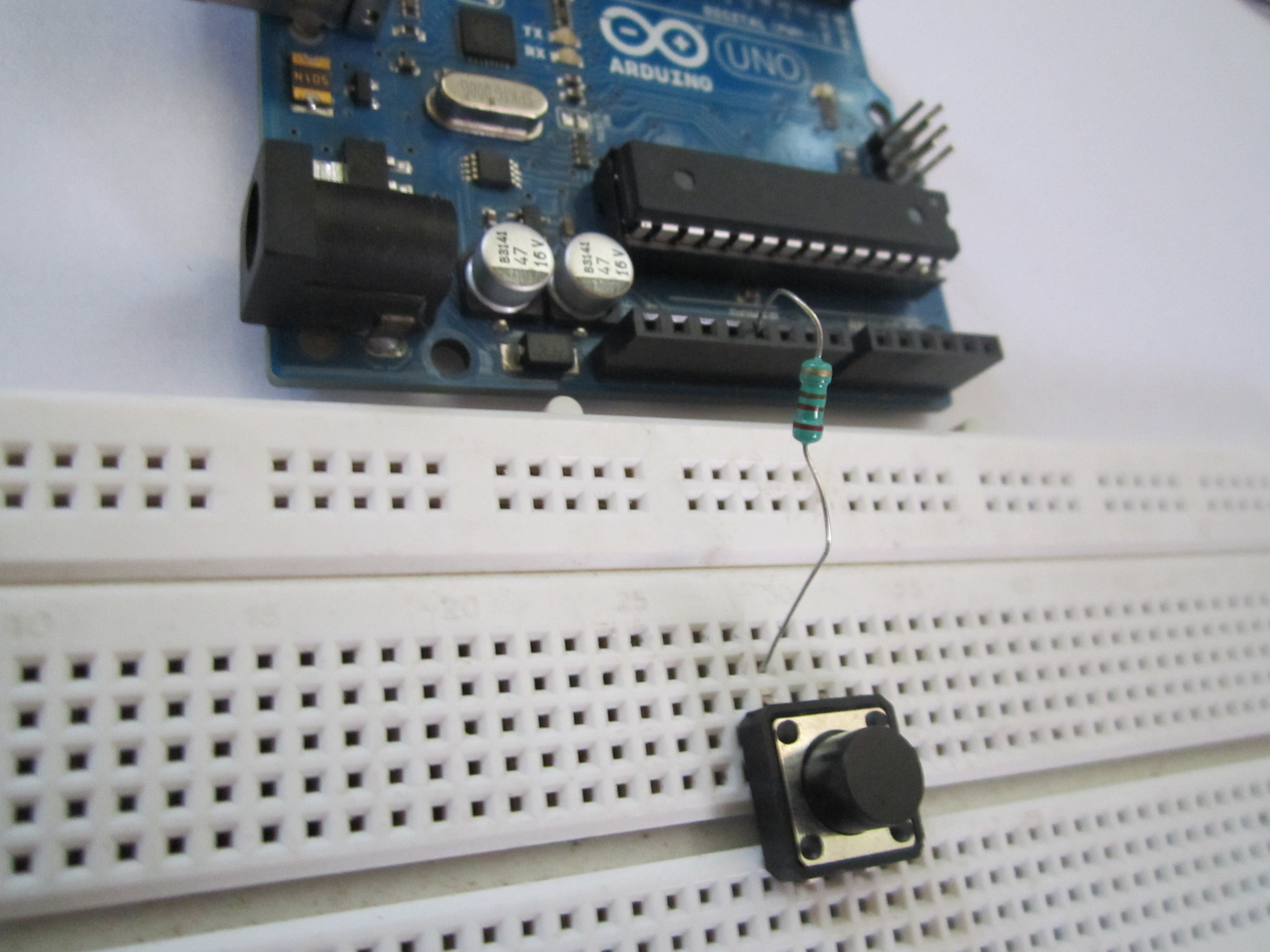
Put the resistor with one end in +5 V and the other end connected with one of the terminals of the switch. Connect the other corresponding terminal to Gnd. The corresponding terminal is usually on the same side as the first one.
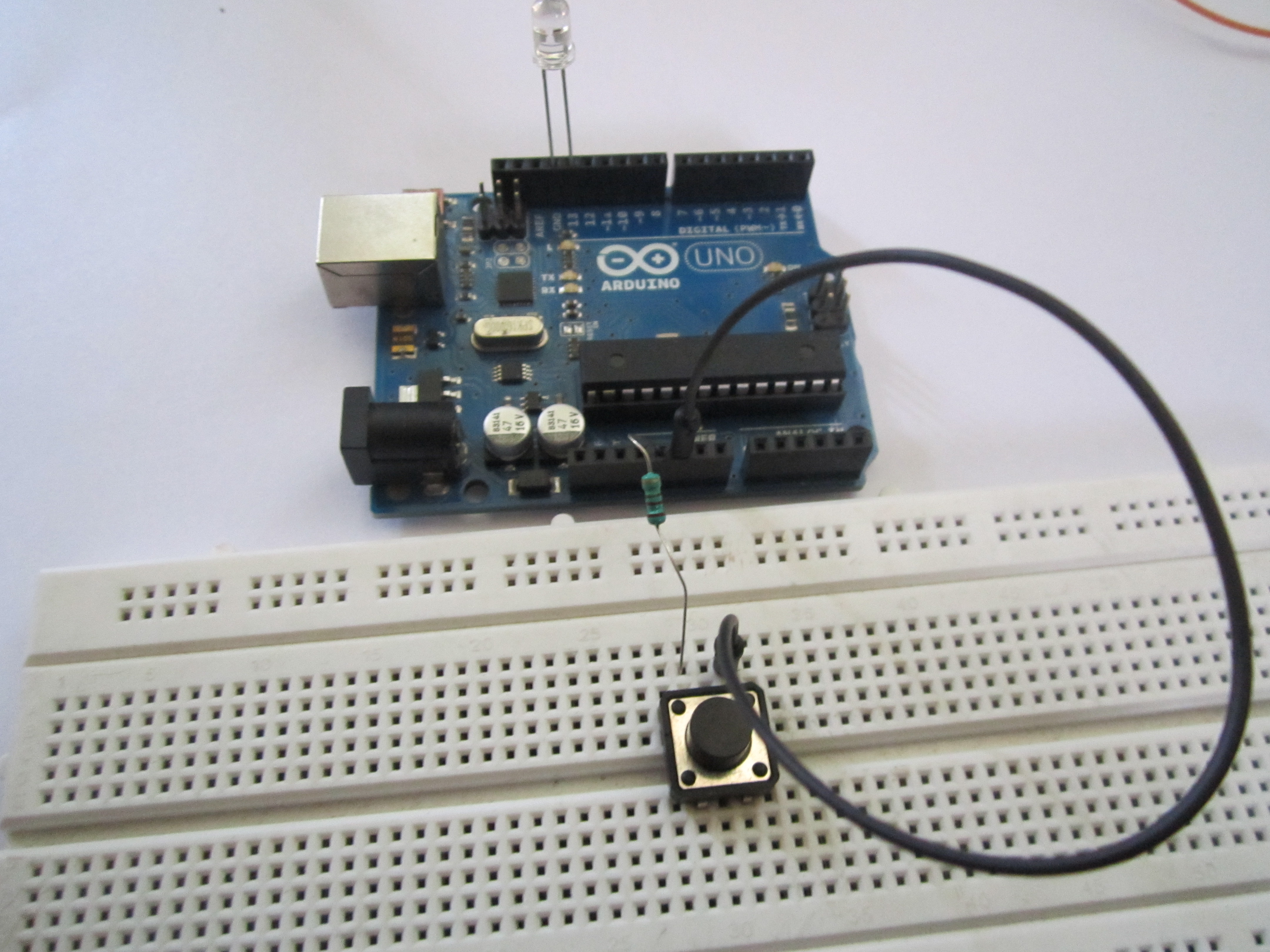
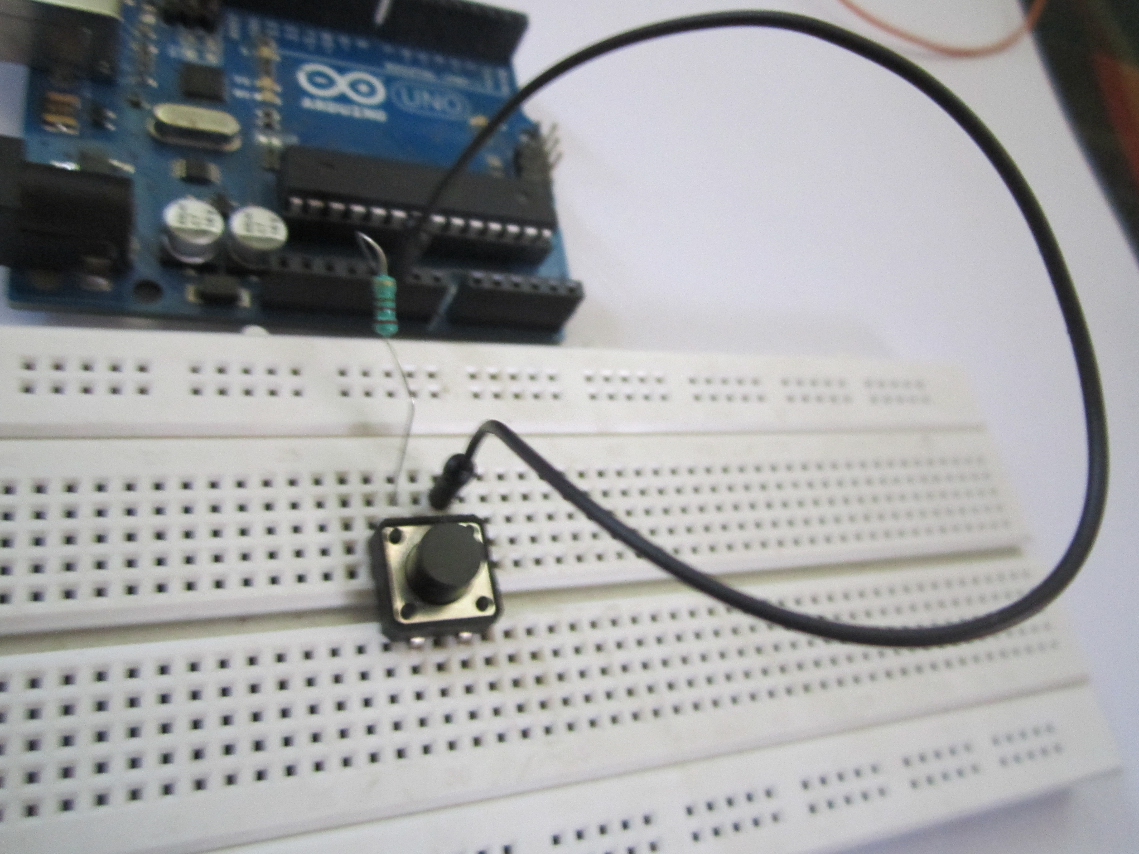
Step 4:
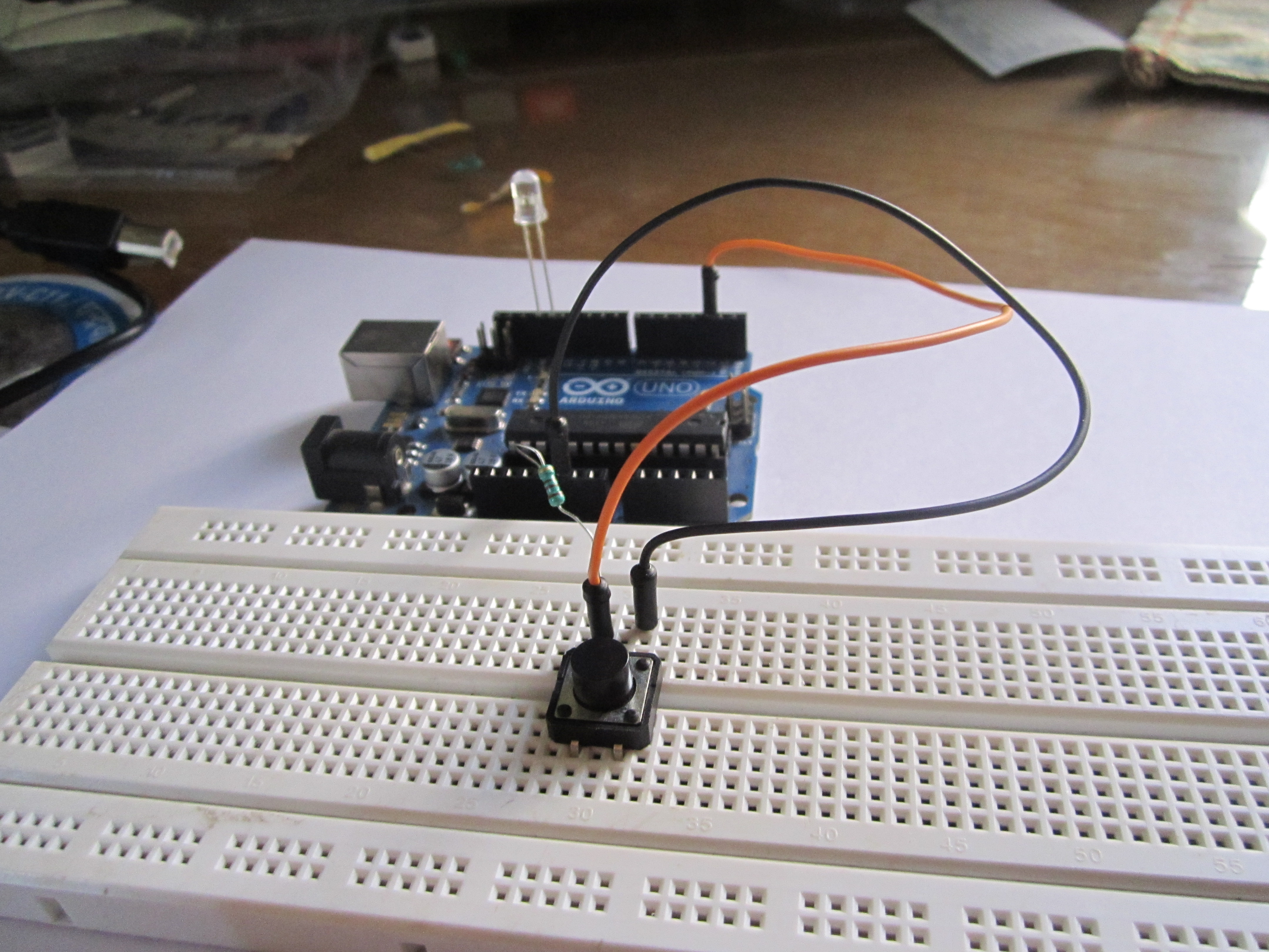
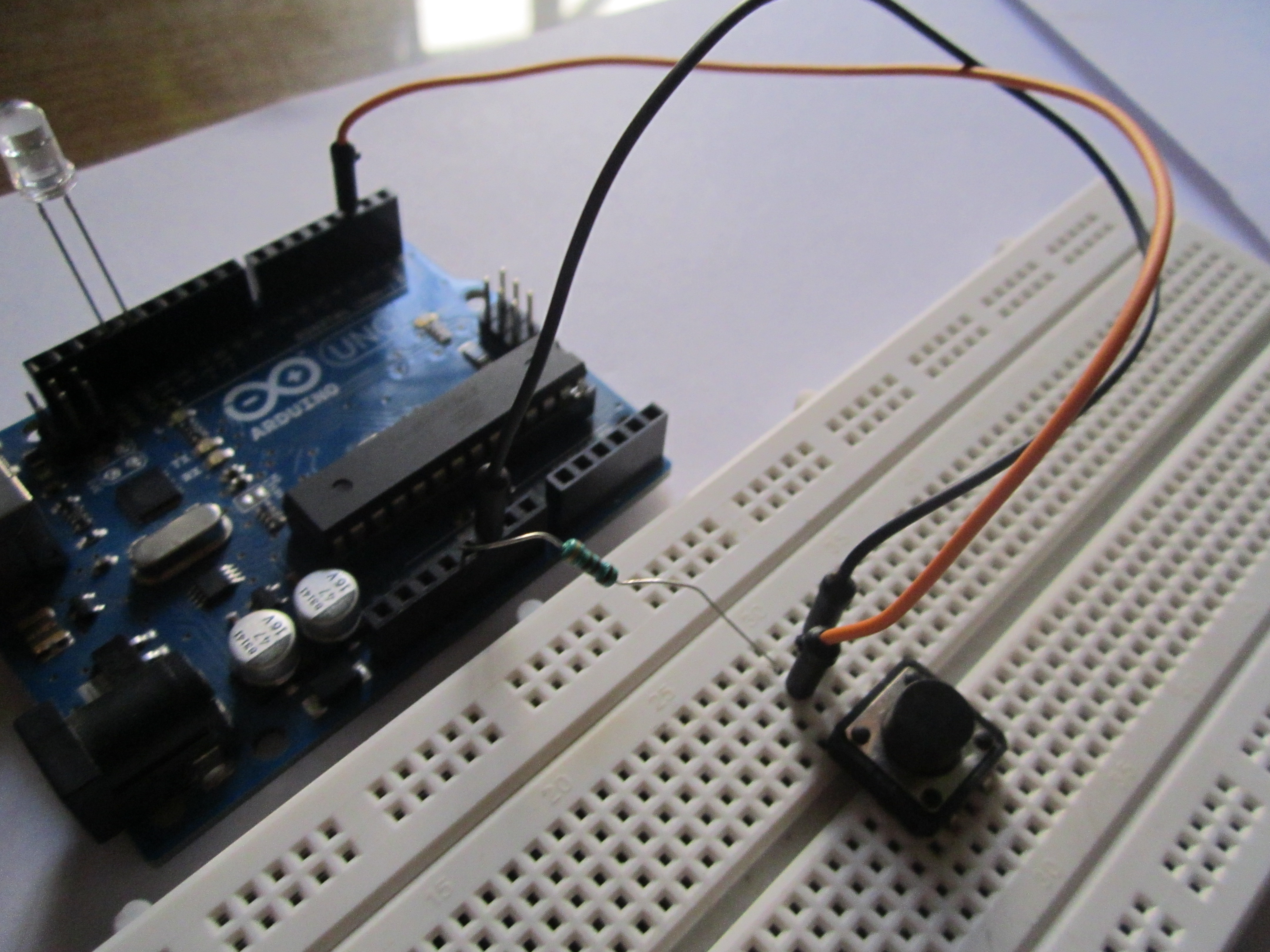
Connect the first terminal (the one with the resistor) to pin 2 on the Arduino and load the program.
Now just press the switch and the LED will light up!
Technical Deep-Dive
Mechanical buttons present two primary engineering challenges: floating states and contact bounce.
- Understanding Pull-up Logic: In this circuit, the pushbutton is connected to a Pull-up Resistor configuration. When the button is NOT pressed, the input pin on the Arduino is connected to +5V through the resistor, reading a stable logic HIGH. When the button is pressed, the pin is connected directly to Ground, reading a logic LOW. Without a resistor, the input pin would be "floating"—picking up electromagnetic noise from the environment and causing the LED to flicker randomly.
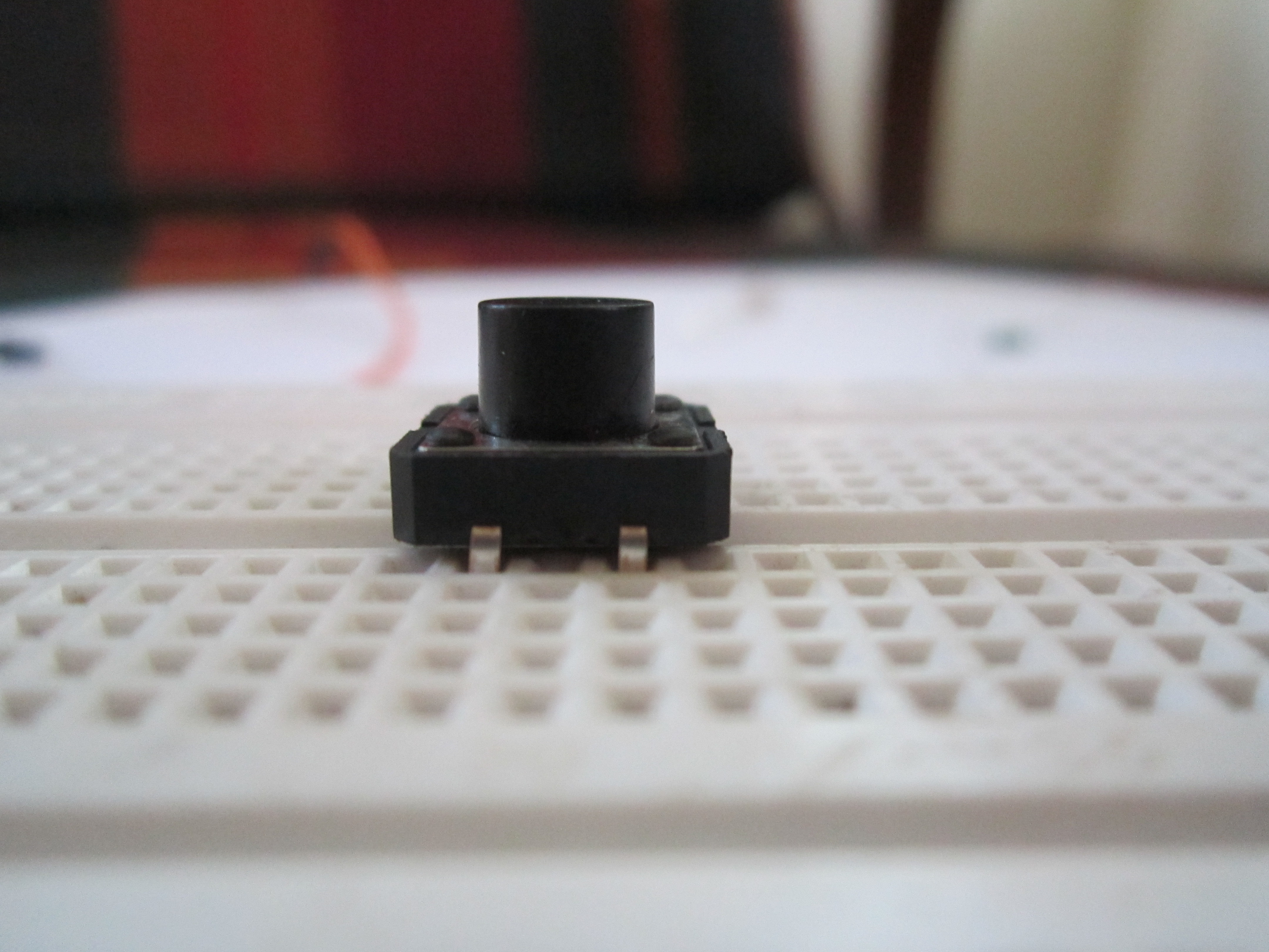
- The 4-Pin Switch: A standard tactile switch has four pins. Internally, these pins are connected in pairs. Understanding which pins are bridged and which are momentary is crucial for breadboard assembly. Using a multimeter in continuity mode is a recommended practice to verify the switch behavior before soldering.
- Digital I/O Operations:
pinMode(2, INPUT): Configures the digital pin 2 as an input. Alternatively, Arduino provides an internal 20k pull-up resistor that can be activated viaINPUT_PULLUP, which simplifies the hardware by removing the external resistor.digitalWrite(13, state): Controls the onboard LED (or an external one connected to pin 13).
- Software Debouncing: Mechanical buttons "bounce" when pressed, creating a series of rapid open/close signals as the metal contacts engage. While not critical for a simple LED project, advanced engineering requires a "debounce" algorithm (using
millis()) to ensure the microcontroller only registers a single press event.