Overview
The main objective of this project is to help people understand the concepts behind PWM. What is it and how it works.
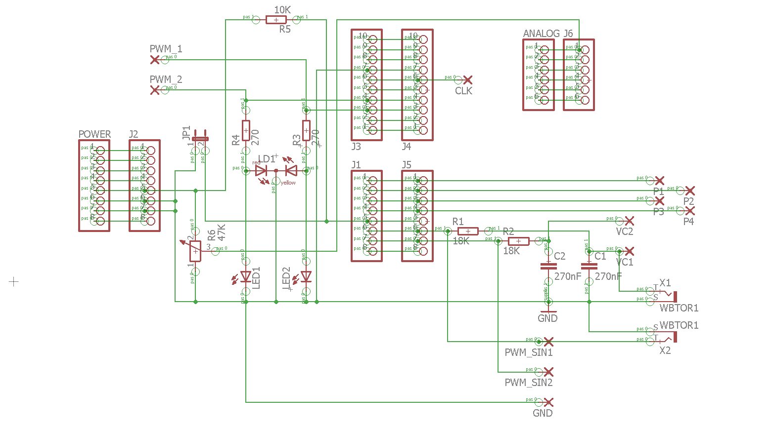
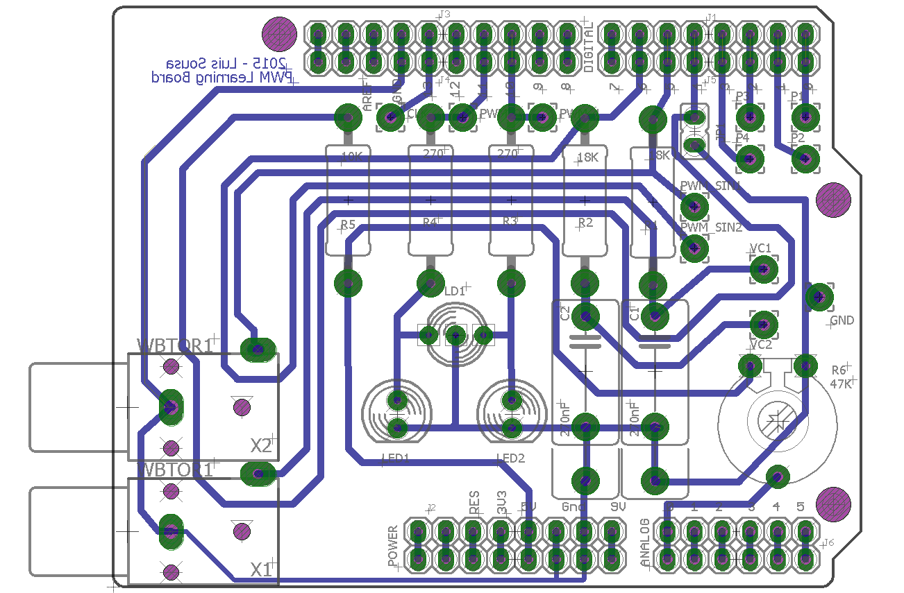
Some students have problems understanding how PWM works, so I decided to build an Arduino shield, that using the Arduino PWM outputs and some easy code, can demonstrate with the help of an osciloscope, how PWM works.
The shield is not mandatory. The circuit can be easily put together in a Breadboard. However if you want a more permanent system, I recomend building the shield.
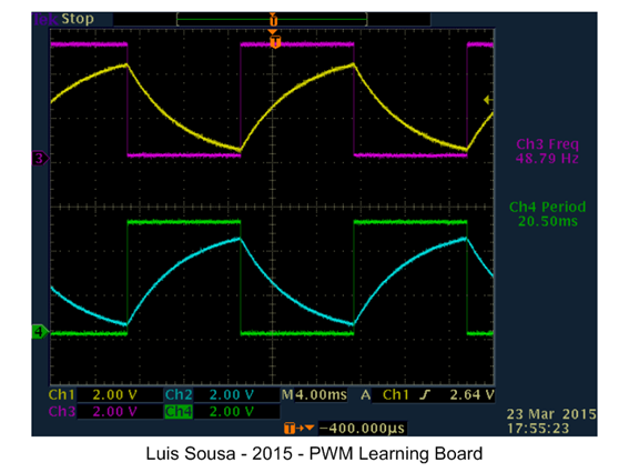
This circuit can also do other things like demonstrating the charge and discharge of a capacitor, with the help of an osciloscope.

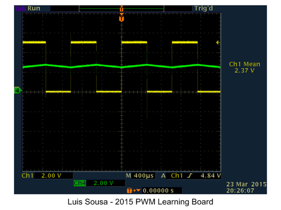
Or demonstrating how duty cycle affects the mean value:
This project also gives the oportunity to the student to familiarize with the Arduino platform capabilities. We will use Analog input, Digital outputs and PWM outputs.
Operating Instructions:
This project has 2 working modes:
- PWM mode (Selectable via Pin D4 = logic 1)
In this mode, we use pins 10 and 11 to generate two complimentary PWM signals that control 2 LEDs (red and green). The duty cycle is dependent of the analog value present at analog Input A0. This analog value is commanded via a potentiometer. Changing the duty cycle, changes the mean value and the luminosity of the LEDs. (One LED increases luminosity, the other decreases).
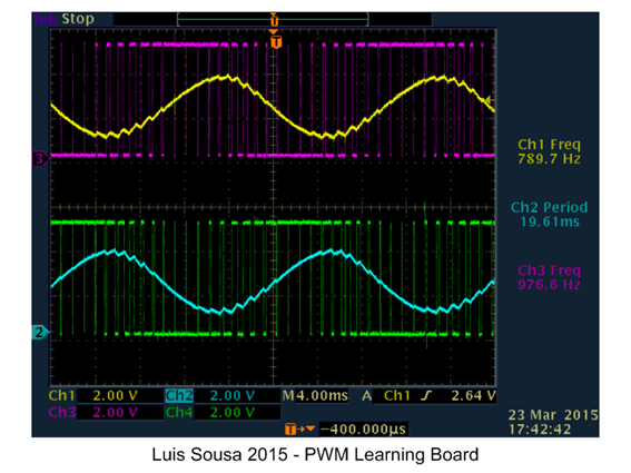
Pins 5 and 6 have a complimentary PWM signal with a duty cycle that varies continuously at a sinusoidal rhythm. Applying a RC filter we can observe a sinusoidal signal.

- Pulse generation mode (Selectable via Pin D4 = logic 0)
With this operating mode, we have on pins D0 and D1 pulses with 10% and 90% duty cycle. On pin 13 we have rectangular wave (500Hz) with a 50% duty cycle
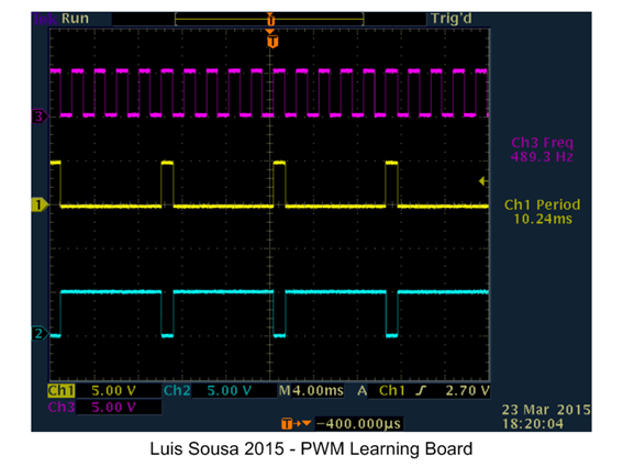
On pins 5 and 6 we have now complimentary square waves that are applied to RC network. We can see at the capacitor terminals the charge discharge curves.
EXPANDED TECHNICAL DETAILS
Educational Signal Visualization
This demonstration board provides a tactile and visual way to understand Pulse Width Modulation (PWM), the cornerstone of modern digital control.
- Hardware Duty-Cycle Mapping: Features a series of LEDs and a dedicated Analog Output (PWM) pin. By turning a physical potentiometer, pupils can see how the duty cycle (the ratio of ON time to OFF time) directly affects the apparent brightness of the LED.
- Oscilloscope Interface: Includes dedicated test-points for an oscilloscope. This allow users to see the physical square-wave changing its width in real-time, bridging the gap between abstract code and physical electricity.
Motor Control Foundation
- Simulated DC Load: (Advanced version) Includes a small DC motor; students can see how the same PWM signal controls not just light, but the rotational speed of hardware, illustrating its use in fans and robotics.