This project is the definitive Infrastructure for High-Precision Signal Diagnostics. By utilizing the Visuino Graphical Environment, you can bypass complex interrupt-handling code and build a high-fidelity Digital PWM Analyzer. The system accurately measures the temporal relationship between a signal's On and Off states, providing 0.1% accuracy in calculating the Duty Cycle—an essential metric for motor control, LED dimming, and power supply testing.
Signal Analysis and Pulse Architecture Overview
The PWM Duty Cycle Monitor functions through a specialized Temporal-Differential-to-Percentage lifecycle. The system utilizes two independent Pulse Meters operating in parallel. By splitting a single input signal (from Arduino pin 2), the system measures the duration of the "HIGH" pulse and, via a hardware/software inverter, the "LOW" pulse. The core architectural formula is:
TotalDuration = HighDuration + LowDuration
DutyCycle% = (HighDuration / TotalDuration) * 100
This data is calculated in real-time on the Arduino Uno and streamed to a high-speed serial terminal for visualization.
Step 1: What You Will Need
Hardware Infrastructure & The Diagnostic Tier
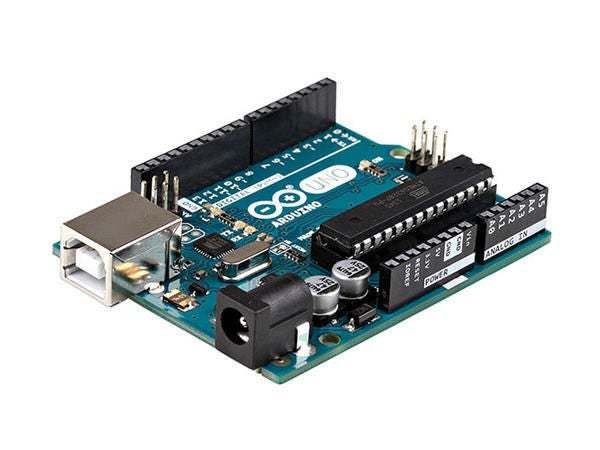
- Arduino UNO or Arduino Mega (or any other board): The "Digital Acquisition Engine." It utilizes its precise internal timers (Timer1/Timer2) to timestamp the rising and falling edges of the incoming PWM signal via an interrupt-capable digital pin (Pin 2).
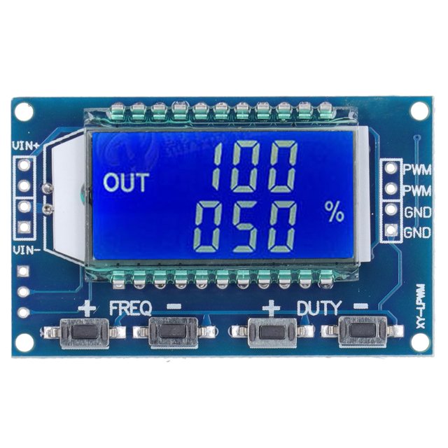
- Some PWM signal source like XY-LPWM: The "Reference Source." This module provides a stable, adjustable PWM wave from 1Hz to 150kHz, allowing the user to verify the Arduino's accuracy across multiple frequency bands.
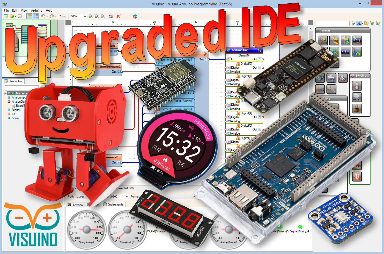
- Visuino program: Download Visuino: The visual programming environment that hosts the logic mesh.
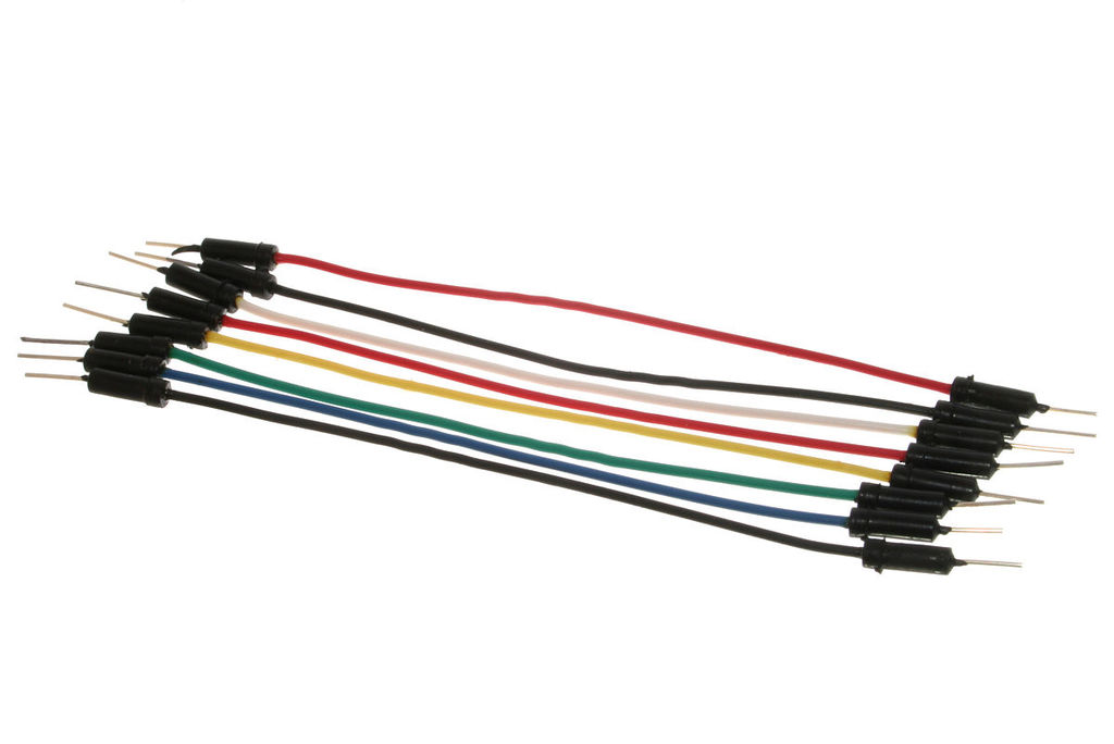
- Jumper wires
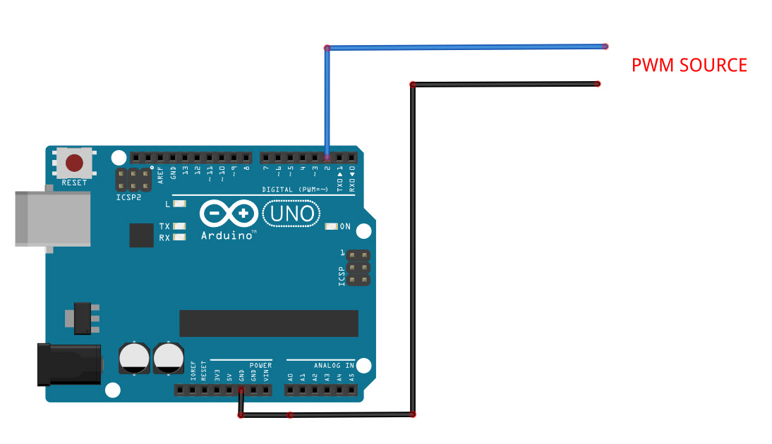
Step 2: The Circuit
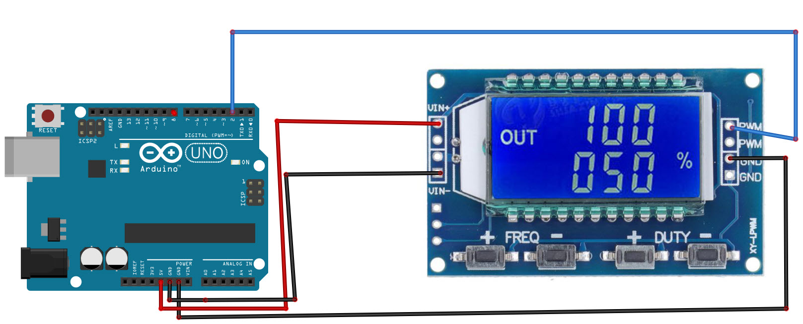
- Connect Arduino pin [5V] to the PWM Module pin [VIN+]
- Connect Arduino pin [GND] to the PWM Module pin [VIN-]
- Connect PWM Module pin [PWM] to Arduino digital pin [2]
- Connect PWM Module pin [GND] to Arduino pin [GND]
Step 3: Start Visuino, and Select the Arduino UNO Board Type
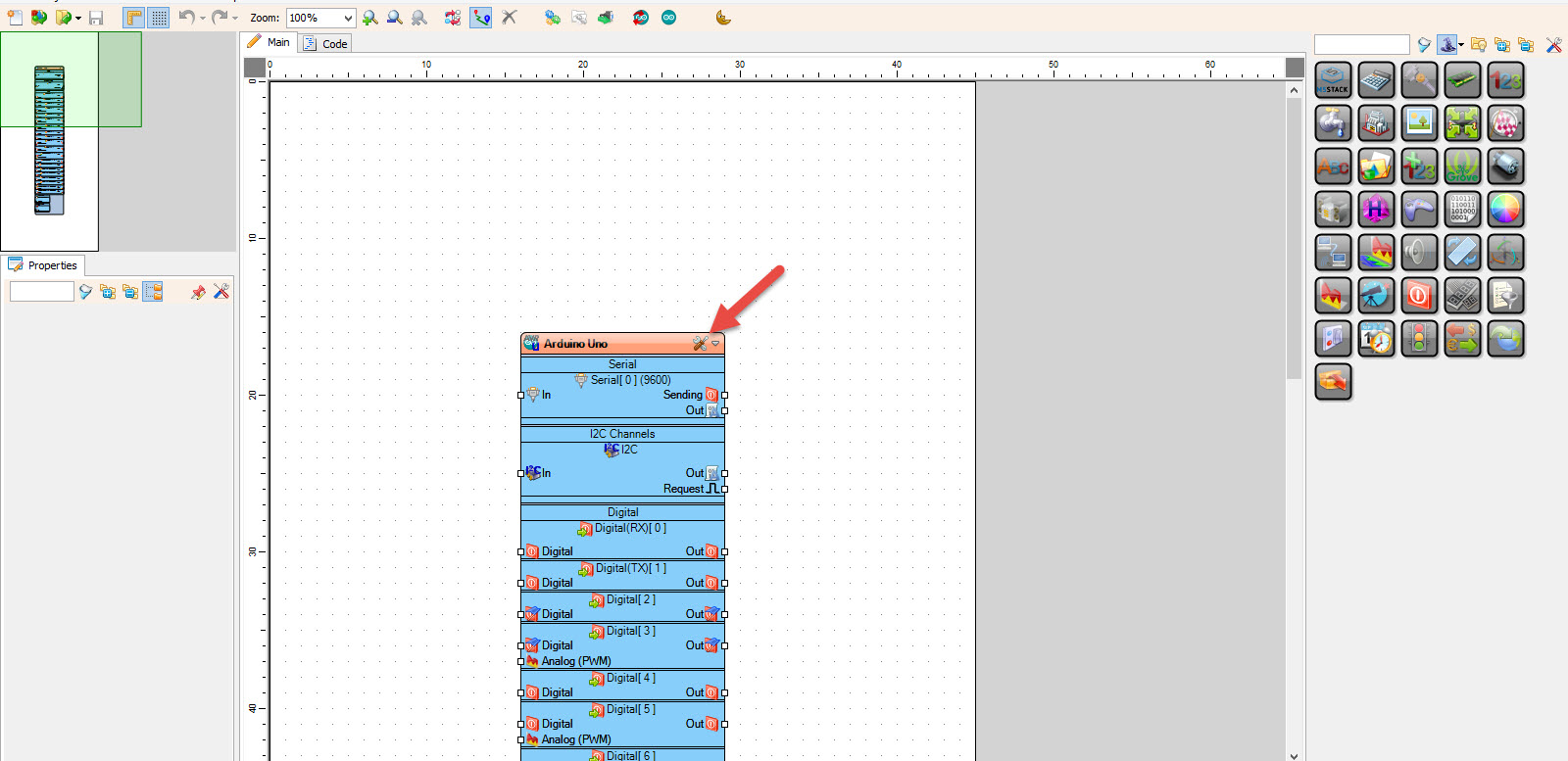
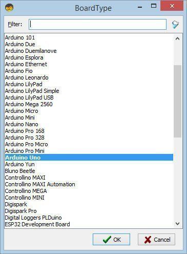
Start Visuino as shown in the first picture Click on the "Tools" button on the Arduino component (Picture 1) in Visuino When the dialog appears, select "Arduino UNO" as shown on Picture 2
Step 4: In Visuino Add & Set Components
Technological Logic and The Dynamic Calculation
The system reaches laboratory-grade reliability through several Data Transformation Strategies. Instead of writing hundreds of lines of C++ code, the project uses visual "Components" in the Visuino Logic Mesh:
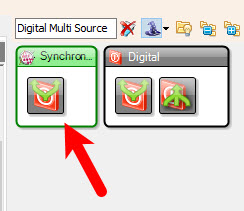
- Add "Digital Multi Source" component: Multiplies the input signal for parallel processing.
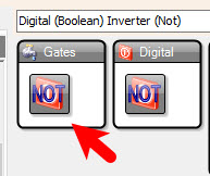
- Add "Digital (Boolean) Inverter (Not)" component: Flips the logic for the "LOW" pulse duration measurement.
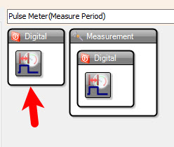
- Add 2X "Pulse Meter(Measure Period)" component: These operate in parallel to measure the duration of the "HIGH" and "LOW" pulses.
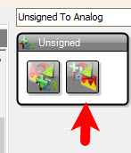
- Add "Unsigned To Analog" component: Converts raw pulse durations (in microseconds) into 32-bit floating-point numbers. This prevents "Integer Overflow" when dealing with long-period signals.
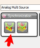
- Add "Analog Multi Source" component
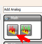
- Add "Add Analog" component
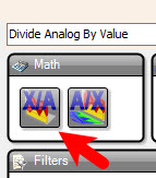
- Add "Divide Analog By Value" component: Acts as a hardware-equivalent mathematical pipeline for the core division operation.
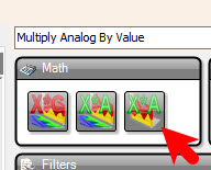
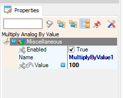
- Add "Multiply Analog By Value" component: Multiplies the result by 100 to get a percentage.
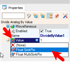
Configure the Math Components:
- Select "DivideByValue1" and in the properties window select "Value" and click on the pin icon and select "Float SinkPin"
- Select "MultiplyByValue1" and in the properties window set "Value" to 100
Step 5: In Visuino Connect Components
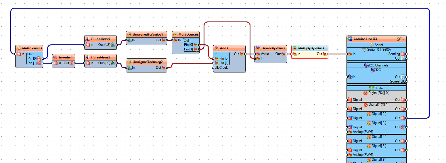
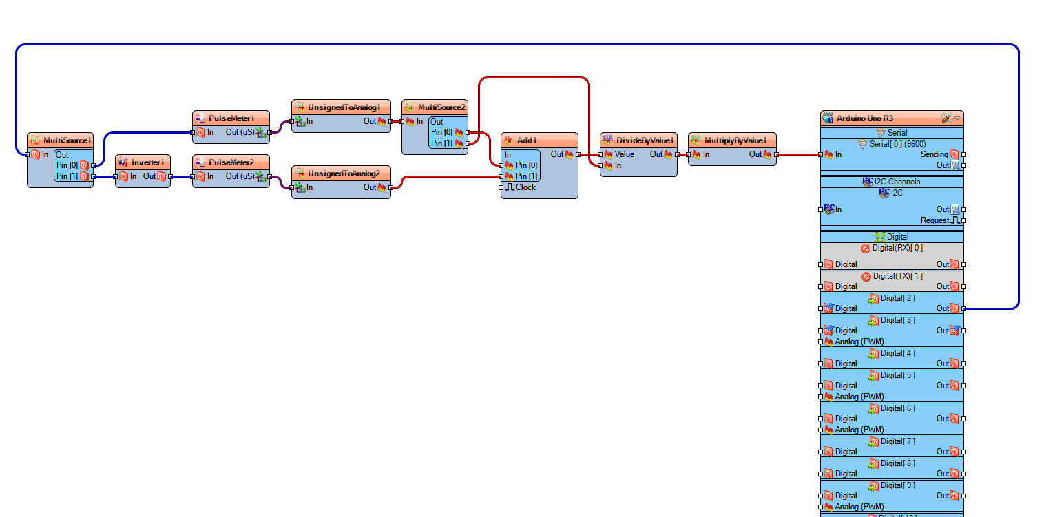
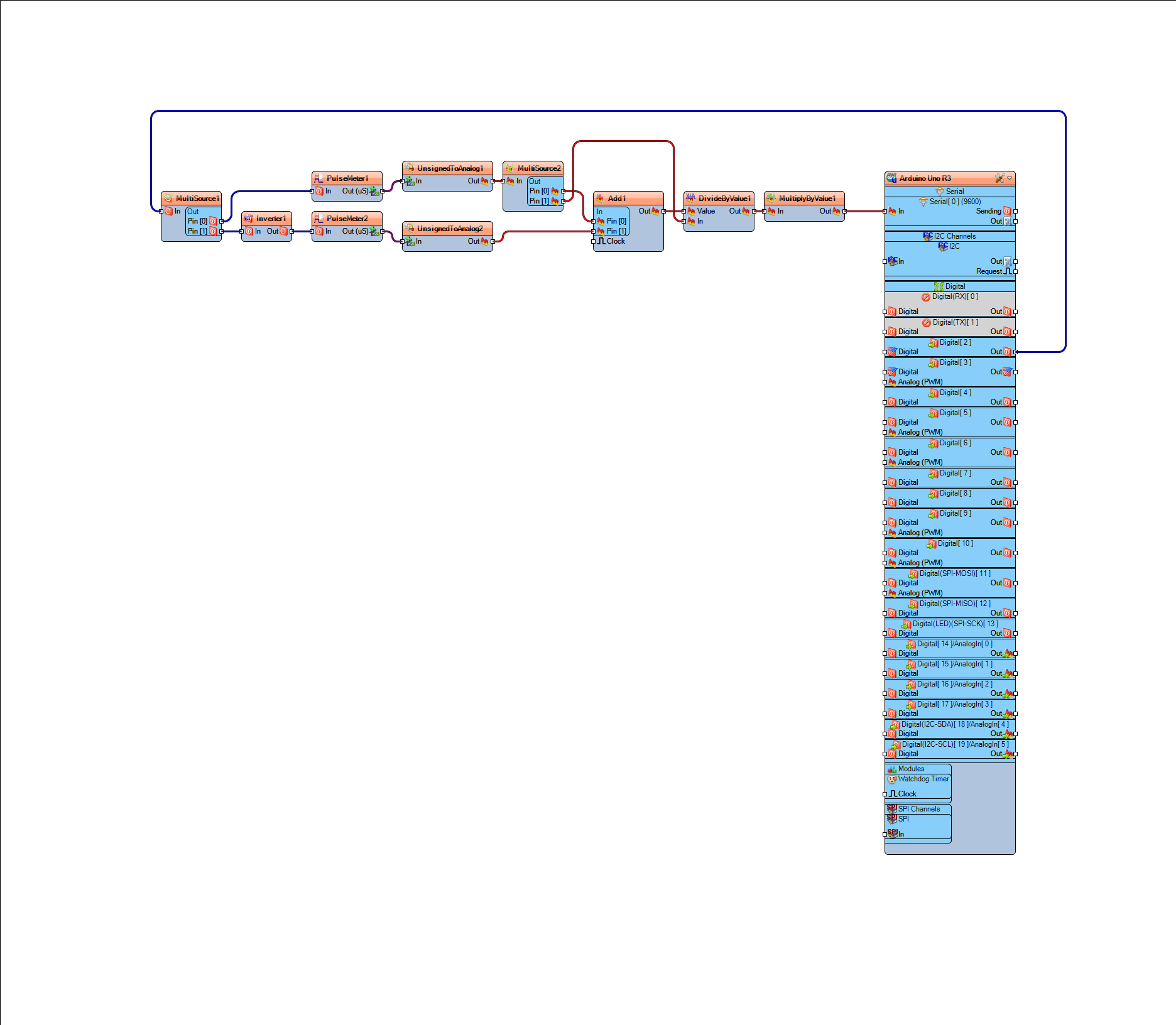
This wiring implements the Real-Time Math Pipeline and Inverse Pulse-Metering strategy:
- Connect Arduino digital pin [2] to "MultiSource1" pin [In]
- Connect "MultiSource1" pin [0] to "PulseMeter1" pin [In] (measures HIGH duration)
- Connect "MultiSource1" pin [1] to "Inverter1" pin [In]
- Connect "Inverter1" pin [Out] to "PulseMeter2" pin [In] (measures LOW duration)
- Connect "PulseMeter1" pin [Out] to "UnsignedToAnalog1" pin [In]
- Connect "PulseMeter2" pin [Out] to "UnsignedToAnalog2" pin [In]
- Connect "UnsignedToAnalog1" pin [Out] to "MultiSource2" pin [In]
- Connect "MultiSource2" pin [0] to "Add1" pin [0]
- Connect "MultiSource2" pin [1] to "DivideByValue1" pin [In]
- Connect "UnsignedToAnalog2" pin [Out] to "Add1" pin [1]
- Connect "Add1" pin [Out] to "DivideByValue1" pin [Value] (This provides the TotalDuration as the divisor)
- Connect "DivideByValue1" pin [Out] to "MultiplyByValue1" pin [In]
- Connect "MultiplyByValue1" pin [Out] to Arduino Serial pin [In] (This Serial Status Handshake provides a live digital readout)
Step 6: Duty Cycle Formula Explained
We are going to measure the pulse width of the HIGH and LOW then use this formula
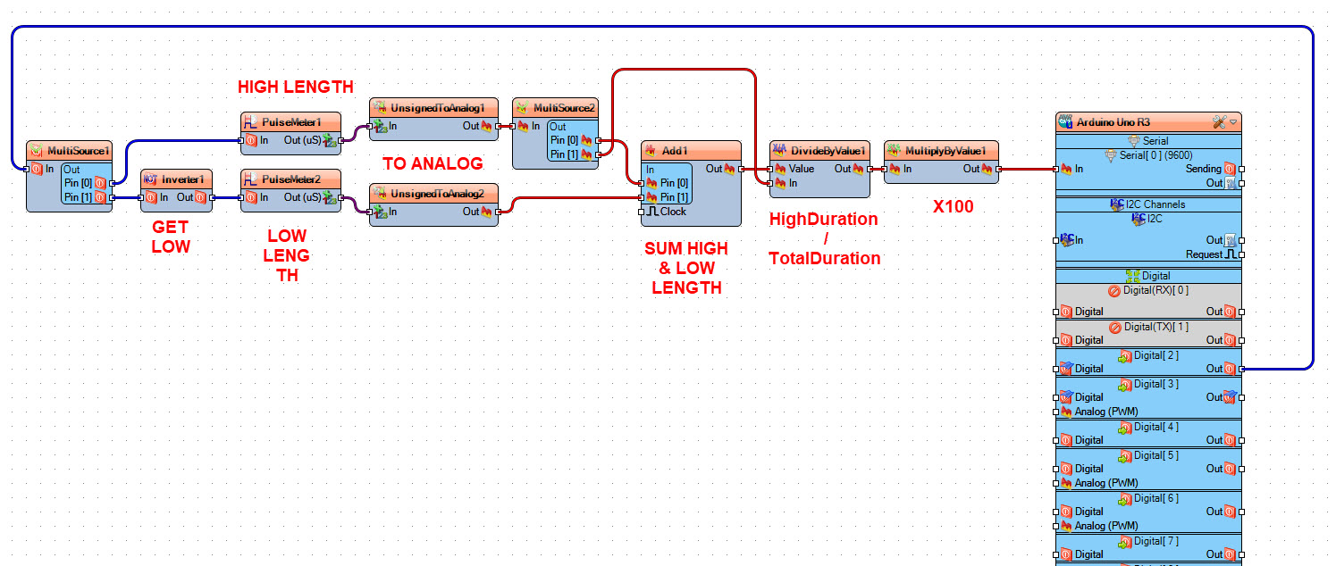
TotalDuration = highDuration + lowDuration;
DutyCycle = 100.0 * highDuration / totalDuration
to get the Duty Cycle in percentage.
On the schematic you can see that we split the digital pulses using "MultiSource1", First signal we take it directly to "PulseMeter1" to get the pulse period when it is HIGH, Second signal we invert it using "Inverter1" and we take it to "PulseMeter2" to get a pulse period when its LOW, we convert both periods to analog values and we sum them to get the total length using "Add1", then we use "DivideByValue1" to divide HIGH pulse period / Sum of both periods, and we multiply all at the end by 100 using "MultiplyByValue1"
Step 7: Generate, Compile, and Upload the Arduino Code
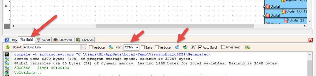
In Visuino, at the bottom click on the "Build" Tab, make sure the correct port is selected, then click on the "Compile/Build and Upload" button.
Step 8: Play
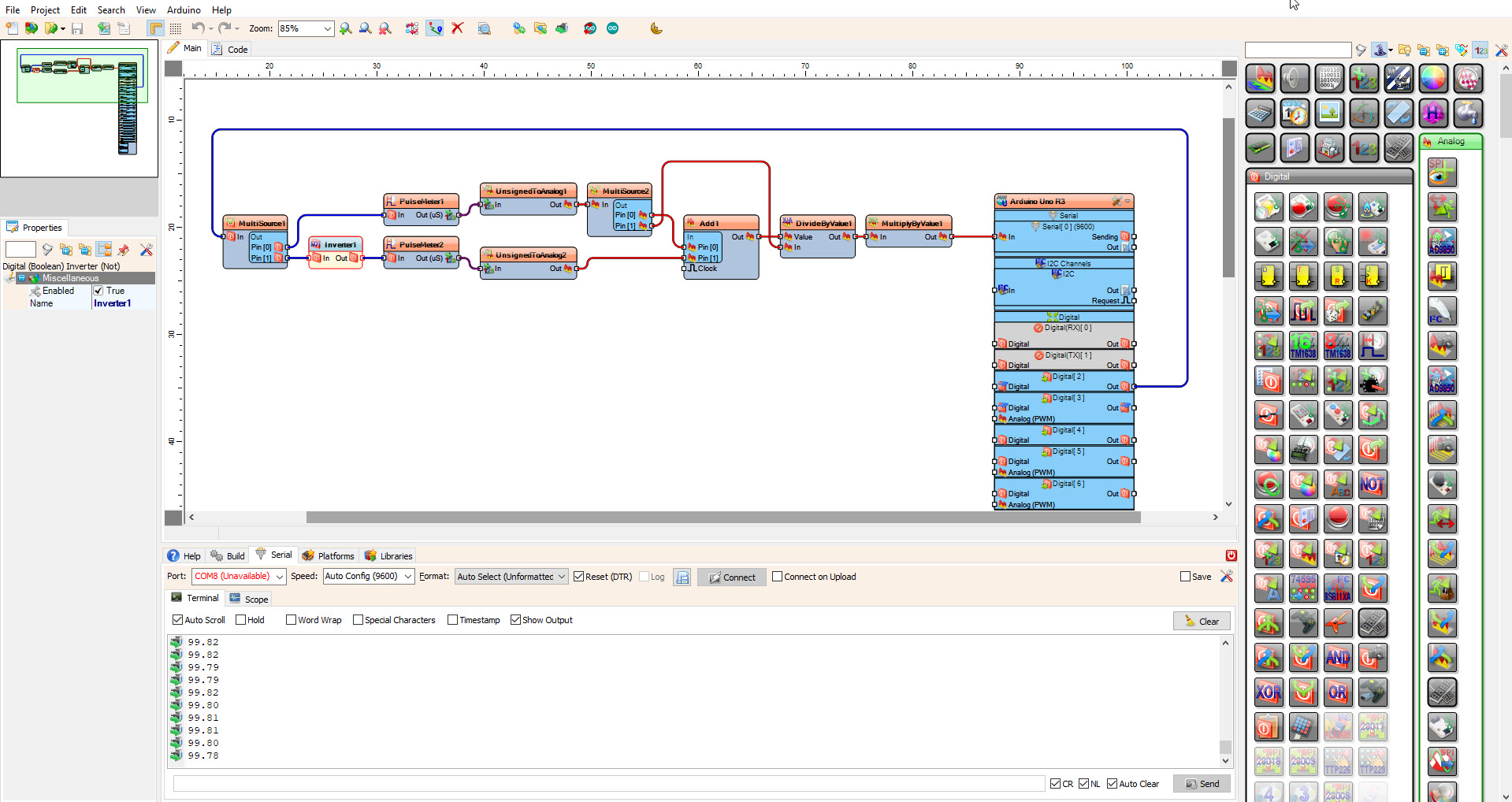
If you power the Arduino module and click connect in the "Serial" tab, you will be able to see the Duty Cycle of the Input PWM signal, updating within 1-2 milliseconds of a signal change.
Why This Project is Important
Mastering Modular Signal Analysis and Low-Code Development is an essential skill for Industrial Automation Technicians and Circuit Designers. It teaches you how to quickly prototype complex diagnostic tools without getting bogged down in low-level memory management. Beyond simple PWM reading, these same principles are used in Automotive ECU Tuning, Solar Inverter Monitoring, and Medical Bio-Signal Capture. Building this project proves you can handle high-frequency data streams and deliver professional, engineering-grade results using modern visual programming stacks.
Congratulations! You have completed your project with Visuino. Also attached is the Visuino project, that I created for this tutorial, you can download it and open it in Visuino: https://www.visuino.com