Project Overview
The "Arduino PPM Signal Reader" is a high-performance interface project designed for robotics and radio-controlled (RC) aircraft. Standard RC receivers output individual PWM signals for each channel, which can quickly consume all the available I/O pins and interrupts on an Arduino. This project overcomes that limitation by decoding the Pulse Position Modulation (PPM) "sum" signal. By using a single interrupt pin, the Arduino can precisely read and demultiplex up to 8+ channels from an RC receiver, providing a clean and efficient way to integrate professional RC transmitters into custom flight controllers, rovers, or industrial remote systems.
RC transmitter is very well suitable for the projects requires a wireless link as it has encrypted links with a good range.
All RC receiver is made to drive servo motors. so there are 3 pins for each channel: ground, Vcc, and signal. here a special kind of signal is used. It sends pulses at some interval. When servo receives 1.5ms pulse it sets to 90 degrees and by varying this value from 1-2ms servo goes to minimum and maximum value. (In the above photo a 6 channel receiver is shown with PPM pin)
So easy method is to measuring pulse width on each pin and map that data as per requirement. but here the problem is that:
- For each channel of the receiver, we need to connect a wire to the Arduino pin. This not only requires lots of connection but also consume lots of pins on an Arduino.
- Most of Arduino just has 2 interrupt pin so if we use more than 2 channels read it to add some delay to our code which may be problematic for some application.
To solve this problem many receivers come with an extra pin called PPM. this PPM pin transmits data of all channels in a single signal.
How PPM Pin Signal Composed?
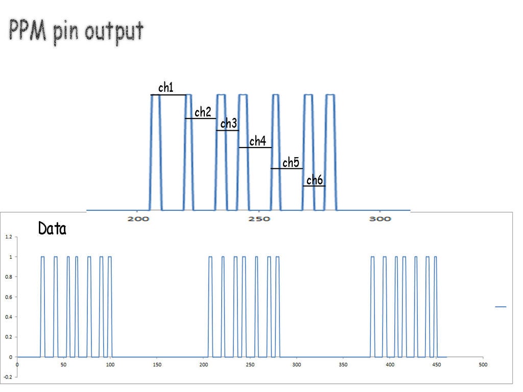
This signal consists of data packets separated by blank space. Here space in between peaks represents the value of the channel. in this case, I have used 6 channel receiver so there are 7 pulses.
So in our code first, we need to detect separation space and then start recording data from the pulses for each channel.
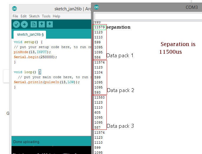
As can be seen in the second image,
all data is separated with approx 11500 microseconds of time. than 6 values are for each channel.
Using the Code:
Here read_me() specified as function:
a=micros(); c=a-b; b=a; x[i]=c; i=i+1;
if(i==15){for(int j=0;j<15;j++) {ch1[j]=x[j];}          i=0;  } }
this part runs on interrupt pin and take 15 time values and store it in an array.
another function read_rc()
this part looks for any space which is higher than 10000microsecond, in our case it detects separation space, and as it detects that space code moves to the next section.
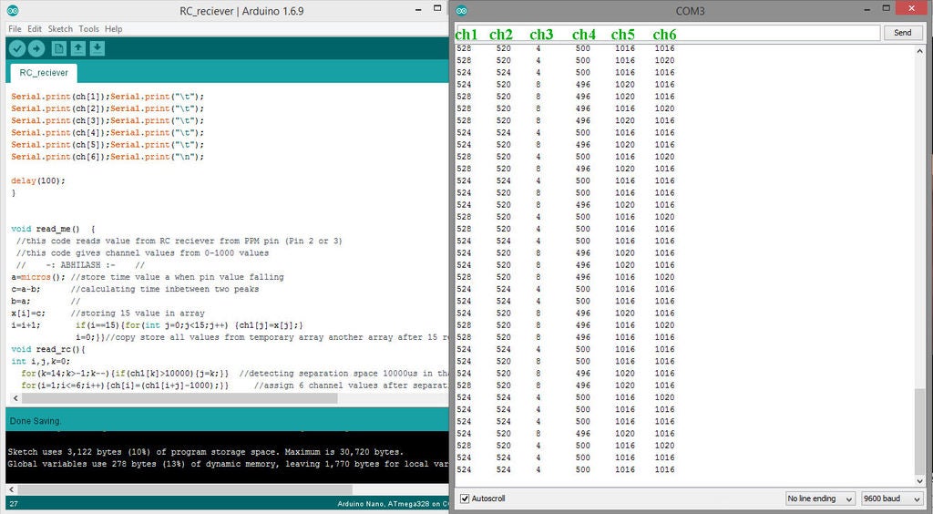
after this space next 6 values are for each channel position it is stored in array named ch[ channel no], here ch[1], ch[2], ch[3], ch[4], ch[5], ch[6] represents value of each channel.
Technical Engineering Depth
Decoding a complex timing signal like PPM requires a deep understanding of microcontroller timing and interrupt handling.
- Interrupt-Driven Pulse Timing: The project leverages the Hardware Interrupt (INT0/INT1) on the Arduino UNO. By using
attachInterrupt(), the Arduino stops its main loop immediately upon detecting a rising or falling edge on the PPM pin. The code callsmicros()to record the exact time of the pulse, ensuring microsecond-level accuracy. This is far more precise than "polling" the pin, which can be affected by the timing of other lines of code. - Packet Synchronization: A PPM frame typically lasts 20ms. Each channel occupies a 1ms to 2ms window, and the entire frame is terminated by a long "Sync Pulse" (usually $>4ms$). The engineering logic in
read_rc()specifically hunts for this long pulse to reset the channel index, ensuring that Channel 1 is always correctly identified and that the data stream doesn't "drift" or misalign. - Non-Blocking Logic: Because the decoding occurs within an Interrupt Service Routine (ISR), the main
loop()remains free to process complex navigation algorithms, sensor fusion, or motor control. This "asynchronous" handling is critical for flight-capable systems where missing even a single millisecond of control can lead to hardware failure. - Signal Filtering & Safety: Professional RC systems are designed for high reliability. This implementation can be further enhanced with "failsafe" logic—detecting if pulses stop arriving and automatically setting the channels to safe neutralized positions to prevent a "runaway" robot or drone.
- Timing Resolution: On a 16MHz Arduino UNO, the
micros()function has a resolution of 4 microseconds. While sufficient for most RC applications, advanced developers might use Timer1 Capture Interupts (ICP1) to achieve sub-microsecond resolution, providing even smoother control for high-precision racing servos.