Project Overview
The "Regulated Power Supply Module" based on the AMS1117 is a critical building block for any robust embedded system. In project development, sensors and microcontrollers often require precise voltage rails (typically 3.3V or 5V) that remain stable even when the primary power source (like a battery or unregulated adapter) fluctuates. The AMS1117 is a series of low dropout (LDO) linear voltage regulators capable of providing up to 800mA of output current, making them indispensable for powering IoT modules, displays, and small actuators.
Main article: Regulated power supply module based on AMS1117
We often use the power supplies like batteries or direct AC/DC supply which are normally in higher ranges compared to the actual requirement for the circuit. In that cases we need this kind of voltage regulators which can regulate and vary the voltage levels for the circuit requirement.
The AMS1117 series of chips are linear voltage regulators with low voltage drop. The modules based on the AMS1117 chip provide constant 3.3V or 5V outputs from an unregulated DC input. It's very compact and can be included in your project schema or you can use it together with a breadboard for circuit testing.
Wiring schema
The connection is pretty easy, it only has VIN (input voltage), VOUT (output voltage) and GND.
The input voltage may vary depending on our module:
- Module with 5V output: VIN should be 6V-12V
- Module with 3.3V output: VIN should be 4.5V-7V
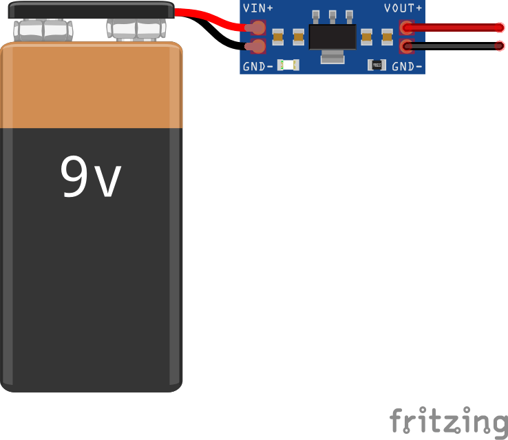
Note: output current must not exceed 800mA.
Technical Deep-Dive
Operating a linear regulator efficiently requires an understanding of Low Dropout (LDO) physics and thermal management.
- LDO Characteristics: Traditional regulators like the LM7805 require a voltage overhead (dropout) of 2.0V or more. The AMS1117 excels by functioning with a dropout voltage of only 1.1V to 1.3V at maximum load. This means to get a stable 3.3V output, the input only needs to be approximately 4.5V, whereas a 5V output requires at least 6.2V.
- Stability and Capacitance: For the AMS1117 to remain oscillaton-free, it requires output capacitance. Engineering best practices suggest using a 10μF or 22μF Tantalum or electrolytic capacitor on the output rail to handle transient load changes and filter high-frequency noise.
- Power Dissipation (Heating): As a linear regulator, the AMS1117 converts excess voltage into heat. The power dissipated is calculated by
P = (VIN - VOUT) * I. For example, if you input 12V to get 3.3V at 500mA, the regulator must dissipate 4.35 Watts of heat. Without a heatsink or large PCB copper plane, the internal thermal protection will trip to prevent damage. - Integrated Protection: The IC features internal current limiting and thermal overload protection. If the output is short-circuited or the temperature exceeds safety limits (usually 150°C), the device shuts down automatically.
Application and Comparison
While switching regulators (buck converters) are more efficient, the AMS1117 is preferred in analog and noise-sensitive RF projects (like LoRa or WiFi) because it generates significantly less electromagnetic interference (EMI). Its small SOT-223 surface-mount package and extremely low cost make it the standard choice for localized voltage regulation on modern digital PCBs.