Like many people, I like to sleep with noise, but most of the time once I am already in bed I'll forget to switch on the fan and then it becomes a back and forth of "Do I really want to turn on the fan or not?" So I decided since I have the time and parts, why not just make an Arduino controlled fan, this project involves high voltage! (Please be careful!!) The fan works by using a IR receiver and relays to control the speed of the fan. Here is a link to how the fan was built!
Infrared Command: The Remote Controlled Fan
The Remote Controlled Fan transforms a "dumb" appliance into a smart device. By utilizing Infrared (IR) technology—the same invisible light your television has used since the 80s—you can build a custom receiver node to command motors from across the room.
Decrypting Infrared Protocols
The air is filled with IR noise from sunlight and lightbulbs. Commercial remotes use 38kHz modulation to ensure their signal is heard.
- The Hardware: An IR Receiver Diode (TSOP38238) strips away the 38kHz carrier wave and passes the raw binary data to the Arduino.
- The Hex Code: You point your dusty Sony TV remote at the diode and press "Volume Up". The
IRremote.hlibrary decodes the invisible pulses into a unique Hexadecimal string, like0xFFA25D. - The Software Logic: You use a
switch/casestatement:case 0xFFA25D: ExecuteanalogWrite(fanPin, 128);(Medium Speed).case 0xFFE01F(Mute button): ExecutedigitalWrite(fanPin, LOW);(OFF).
Managing High Current (The Relay/MOSFET)
A cooling fan motor pulls 1 to 3 Amps of electricity. An Arduino pin can output 0.04 Amps. If driving a small 12V PC fan, you must use a heavy-duty TIP120/IRLZ44N Transistor acting as a digital valve. If you are hacking a giant 110V/220V AC oscillating room fan, you must use a 5V Relay Module to safely switch the mains power!
Needed Parts
- Arduino Uno/Nano: The decoder.
- IR Receiver Diode (1838 or TSOP38238).
- Any old TV/DVD Remote Control.
- DC Fan + MOSFET (safe) OR AC Fan + Solid State Relay (dangerous).
STEP 1: Button Assignment
Find out your remote control's button assignment. Each remote control has its own code for what each button does, for example if you press the volume down key on your remote then you will send a code to your TV, that code is then executed in the program to decrease the volume on your TV.
#include <IRremote.h>
int RECV_PIN = 12; // the pin where you connect the output pin of IR sensor (CHANGE Depending on your Arduino)
IRrecv irrecv(RECV_PIN);
decode_results results;
void setup()
{
Serial.begin(9600);
irrecv.enableIRIn();
{
void loop()
{
if (irrecv.decode(&results))
{
int results.value = results;
Serial.println(" ");
Serial.print("Code: ");
Serial.println(results.value);
Serial.println(" ");
irrecv.resume();
}
We use the code above to find out each of the button's code in Decimal format with the Serial Monitor. Keep these values safe! I would suggest you plan out what you want each button to do and make a table with the button and it's ID.
STEP 2: Materials
Gather your materials,
Once you have gathered your materials you must acknowledge that you are going to be working with high voltage!
STEP 3: Find out your fan's wire code
First you must understand how your fan works:
Electric fans have a motor that runs on electricity and is connected to the fan blades through a shaft. The motor drives this rotor shaft, which turns the fan blades at various speeds based on the motor's speed setting. Depending on the kind of electric fan, the number of blades and the motor's general revolutions per minute can vary significantly.
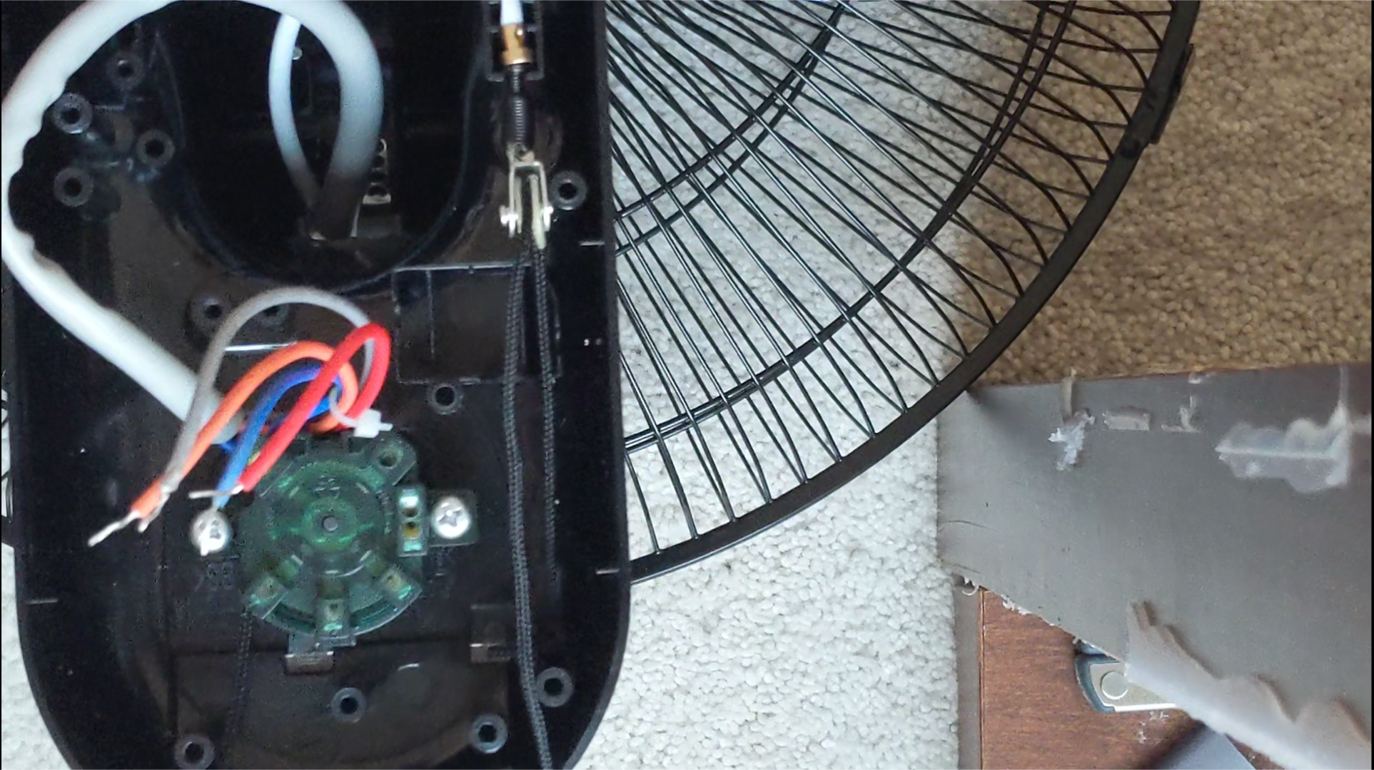
Each fan has a different wiring code, for example my fan has 4 different wires including a Blue, Red, Orange, and a Gray. Each of these wires does something, in my case the Blue wire is common (neutral), the Red wire is for speed 3 (connected to live), the Orange wire is for speed 2 (connected to live) and at last there is a Gray wire that is for speed 1 (connected to live). Here is an image:
NOTE: You may have another wire that is for automatic oscillation motor
STEP 4: Wiring
Once you have identified your fan's wire color codes, then you may begin to hook up the electronics part of the fan, You should attach the fans speed wires directly to the relay's NO terminals as shown in the video, the relay's COM terminals will be connected together and attached to the live wire.
STEP 5: Electronics
After all of the fan's speed wires are connected to the relay, then you can proceed to the Arduino wiring of the fan! Connect the fan exactly to the Schematic provided below:

STEP 6: Coding!!
Once all of the electronics have been wired up, then you can move on to the code!
Here is the code:
#include <LiquidCrystal.h>
#include <IRremote.h>
int RECV_PIN = 12;                 // Pin no. on Arduino (Change depending on your Arduino)
int Speed1 = 8;                    // Pin no. on Arduino (Change depending on your Arduino)
int Speed2 = 9;                    // Pin no. on Arduino (Change depending on your Arduino)
int Speed3 = 10;                    // Pin no. on Arduino (Change depending on your Arduino)
int OSC = 11;                       // Pin no. on Arduino (Change depending on your Arduino)
int relay[] = {0,0,0,0,0};         // no. of relays present / the state of the relay
const int rs = 7, en = 6, d4 = 2, d5 = 3, d6 = 4, d7 = 5;   // Pin no. on Arduino (Change depending on your Arduino)
 LiquidCrystal lcd(rs, en, d4, d5, d6, d7);
The code above first declares all of the necessary libraries needed in order for the program to work successfully, all of these programs can be found with the library manager in the Arduino IDE shown below:
the next part of the code declares all of the pins used in the Arduino
#define speed1 ________             // button code for speed no.1  (CHANGE Depending on your Button Code)
#define speed2 ________             // button code for speed no.2  (CHANGE Depending on your Button Code)
#define speed3 ________             // button code for speed no.3  (CHANGE Depending on your Button Code)
#define power  ________             // button code for ON/OFF      (CHANGE Depending on your Button Code)
#define Osc    ________             // button code for Oscilation  (CHANGE Depending on your Button Code)
IRrecv irrecv(RECV_PIN);
decode_results results;
The next part defines all of the button codes that were previously found. Replace the dashes with your code!
In order for the relay to work we have to use the switch statements and case statements:
 if (irrecv.decode(&results)) {
   unsigned int value = results.value;
     switch(value) {
       case speed1:
         lcd.print("");             // clears the LCD
         lcd.setCursor(1, 1);       // sets the cursor
         lcd.print("# 1");           // prints speed 1
           if(relay[1] == 0) {
              digitalWrite(Speed1, HIGH);    // Sets the speed to 1
              digitalWrite(Speed2, LOW);     // makes sure that all other speeds are turned off to prevent multiple voltages going to the fan
              digitalWrite(Speed3, LOW);     // makes sure that all other speeds are turned off to prevent multiple voltages going to the fan
              relay[1] == 1;                 // just an indicator for the program that speed 1 is currently ON
}
Happy Making and good luck on your project and be very careful handling mains voltage!
Final Product: