Interactive Puzzles: Solving Hardware Logic Hurdles
The "Riddle Keypad Project" is a deep dive into embedded system design, created as a summative project for the TEJ3M curriculum. It challenges the standard "Password Entry" trope by forcing the user to solve a riddle displayed on an LCD screen and input the answer via a 4x4 matrix keypad. This project is as much about User Interface (UI) optimization as it is about back-end coding.
Solving the Pin Constraint Problem
A standard 16x2 LCD requires 6 digital pins, and a 4x4 keypad requires 8 pins. On an Arduino Uno, this leaves almost no room for additional sensors or actuators.
- I2C Efficiency: To solve this, the project utilizes a Sunfounder I2C LCD. By using the Inter-Integrated Circuit (I2C) protocol, the display is controlled using only two pins (SDA/SCL), freeing up pins 2 through 9 for the high-density keypad matrix.
- Matrix Scanning: The code uses the
Keypad.hlibrary to perform high-frequency scanning of the rows and columns, detecting when a crossing point is closed by a physical press.
UI/UX Refinement: Cursor and Display Logic
Displaying a riddle while simultaneously showing user input on a small 16x2 screen presented a significant layout challenge:
- Static vs. Dynamic Content: The top line remains static to display the riddle, while the bottom line dynamically updates with the user's keystrokes.
- Cursor Management: Instead of a traditional horizontal scrolling loop, which can be disorienting on a small screen, the developer implemented a "character replacement" logic. Each new key press appears in a specific position, keeping the visual focus steady for the user.
- State Machine Logic: The Arduino constantly compares the input string against a pre-defined "Answer Key." Upon a match, it triggers a "Correct" state, which in a real-world scenario could be used to actuate a servo-motor lock or clear a digital gate.
Real-World Engineering Roles
This project simulates a professional development environment where different roles must converge. The Programmer handles the library integration and logic; the Designer focuses on the mechanical fit and 3D-printed housing (using Dremel Slicer); and the Engineer ensures the physical wiring is robust and noise-free.
A lot of changes and troubleshooting had to be done to my original code. The first challenge I had was during the designing stage. I could not use the tinkercad LCD because it would have taken up too many digital ports on the Arduino, not leaving enough for the keypad to connect to the Arduino. I solved this by using a sunfounder LCD. This means I only had to use four ports (two analogs, one ground and one power). This freed up ports 2-9 to use for the keypad. Another major issue I had was getting the placement of the numbers. My original code only used one line, but instead of having it say “Enter a password” I wanted it to ask a riddle, and have the password be the answer to the riddle. Because the riddle took up two lines, I had to change the placement of the numbers that displayed as you typed them. The problem was that the lcd.setCursor was using the variable data_count and not a value on the lcd itself and was inside the loop. This made it difficult to move the starting position of the loop to somewhere in the middle of the lcd. I tried to fix this by having the top line of the lcd scroll horizontally and the bottom stay static, but Arduino does not have this option built in to the code meaning it would have to be done through its own custom for loop. I decided against this because it would make my code harder to read and more complicated unnecessarily. My solution was that I had each new number replace the one before it on the same position on the lcd, as opposed to the loop that incremented by one each time and moved the cursor one over each time a button was pressed. This new design made my code simpler and easier to follow, and didn’t sacrifice any functionality. Some things that went well was the first part of my code. I had to learn how to use the keypad library, how to set it up and configure it by giving each button a value. This part was a very smooth learning. There are many real work applications using this concept. This same concept could be used with variations to unlock doors or panels by changing what happens when the correct answer from displaying “correct” to turning a motor that will move a lock, or by sending an analog signal to an external device. In the real world, one team would be dedicated to the coding (programmers), one for designing the build (designers/engineers), and one for building it (engineers).
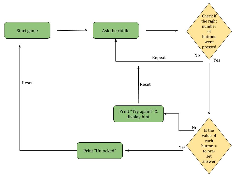
Logic diagram of the code