Welcome to the Riddle Treasure instructions!
Timer & Rotary
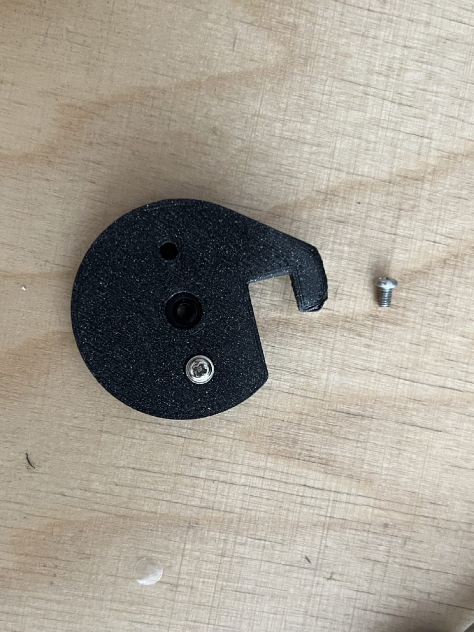
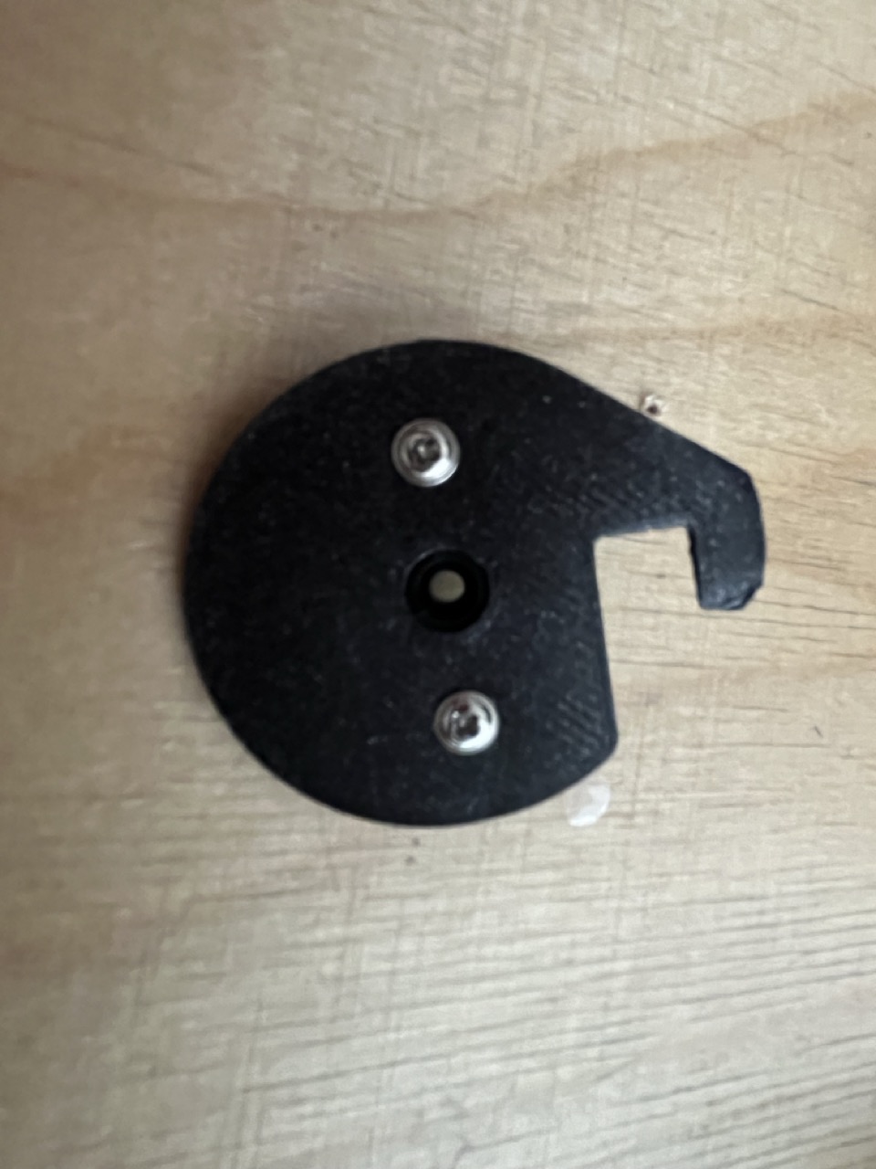
Let's first attach the 3D printed knob to the Modulino knob.
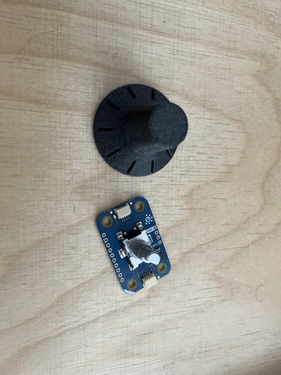
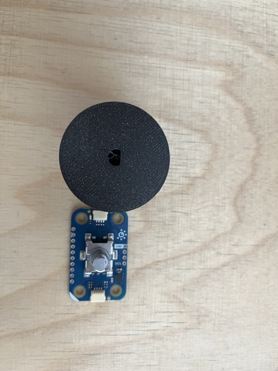
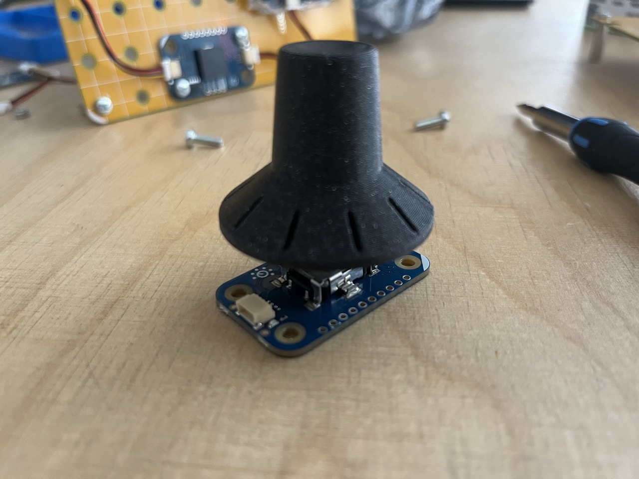
Don't use too much force, let the heavy part of the hammer do the majority of it.
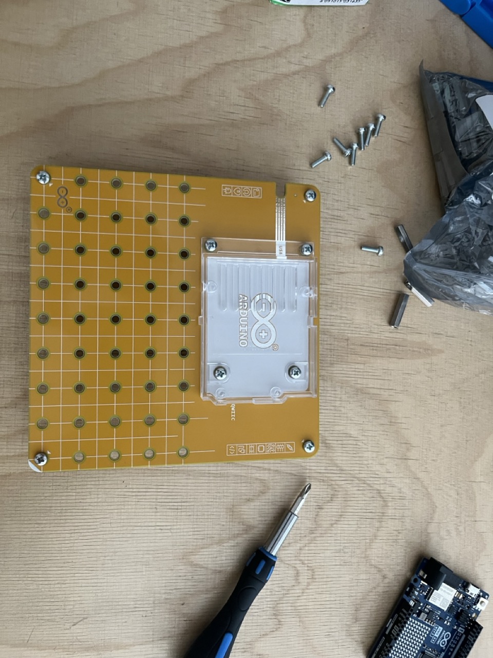
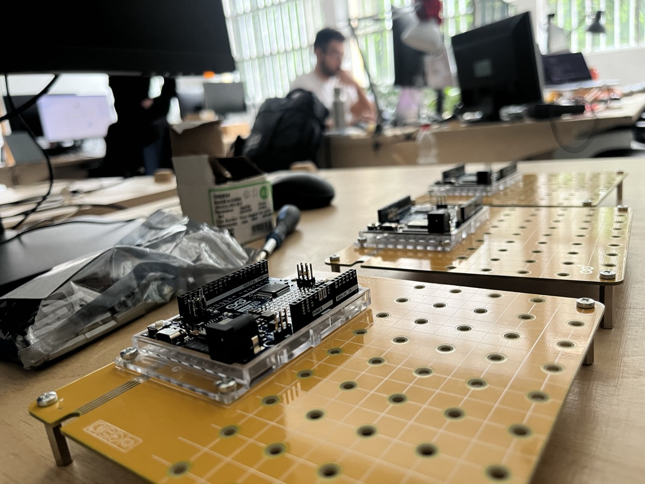
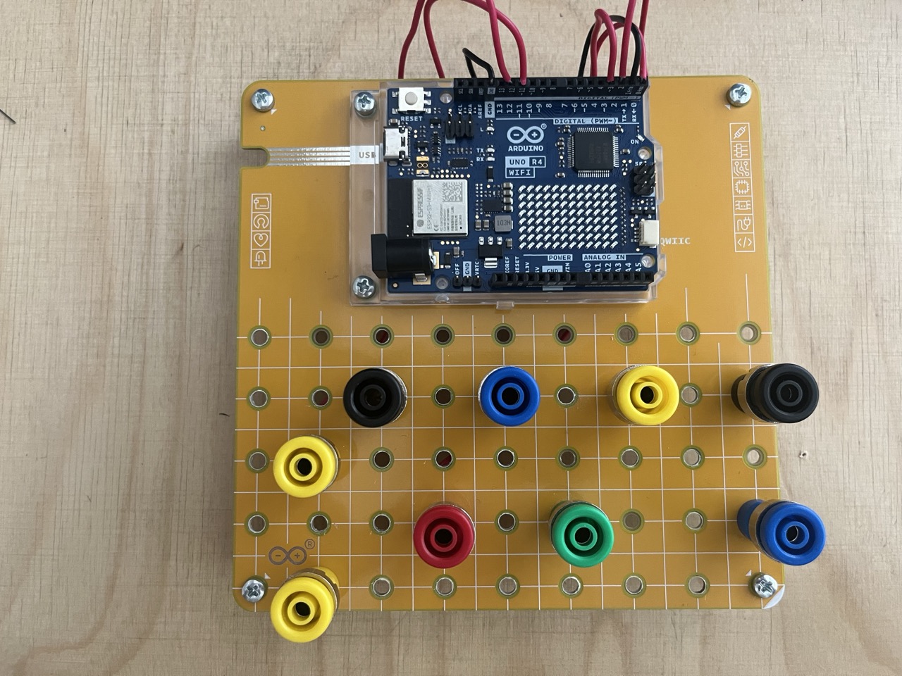
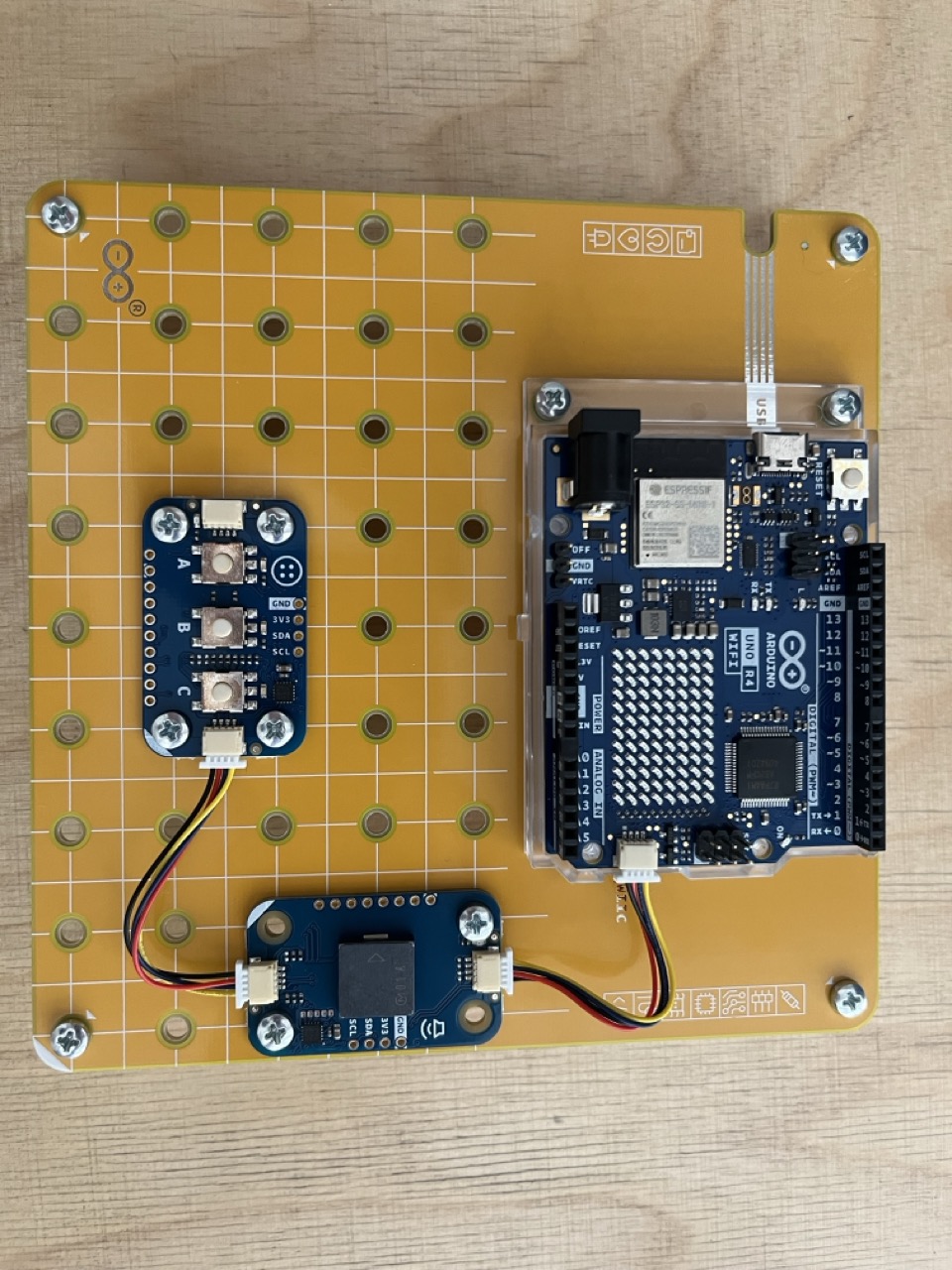
Let's assemble the Arduino Uno R4 Wifi with the Modulino Knob, Pixel and Buzzer.
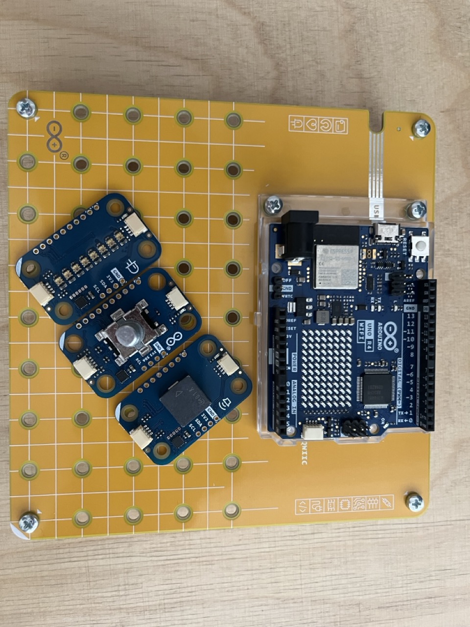
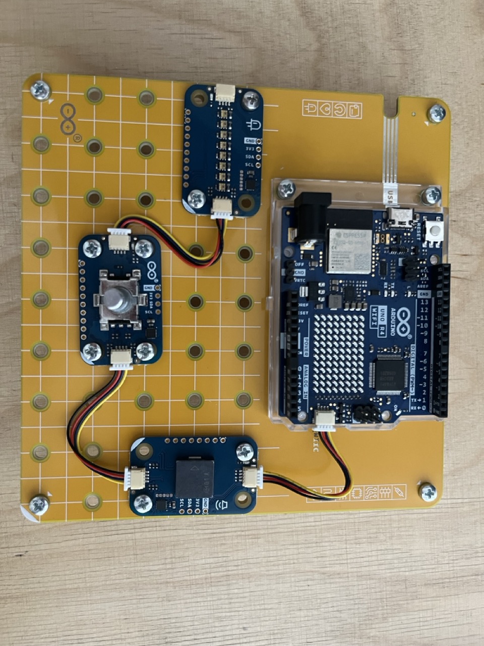
Let's connect each Modulino using the Qwicc cable connecting them to the Arduino UNO Qwicc port.
Upload the Rotary sketch: https://github.com/giulio93/RiddleTreasure/tree/main/Rotary
Banana Field
The banana field needs a little bit of work:
Print the solid interface and place one banana holder for each word.
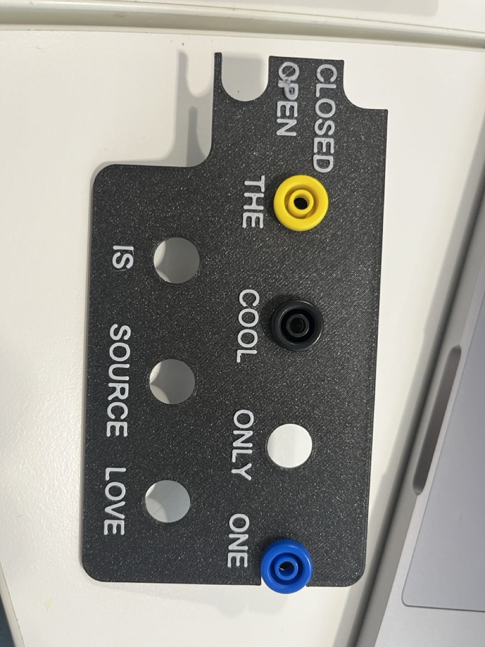
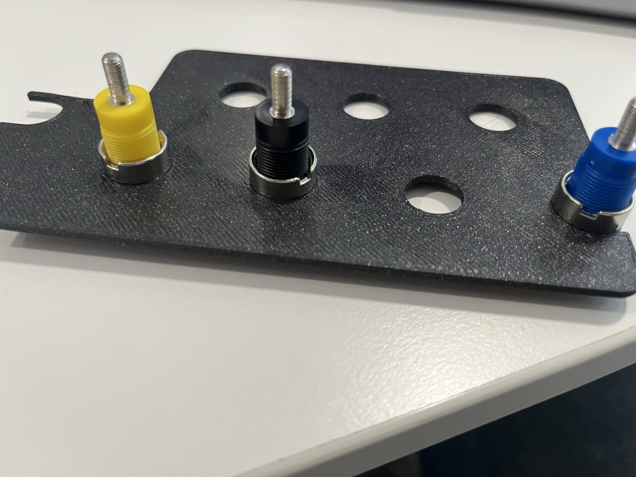
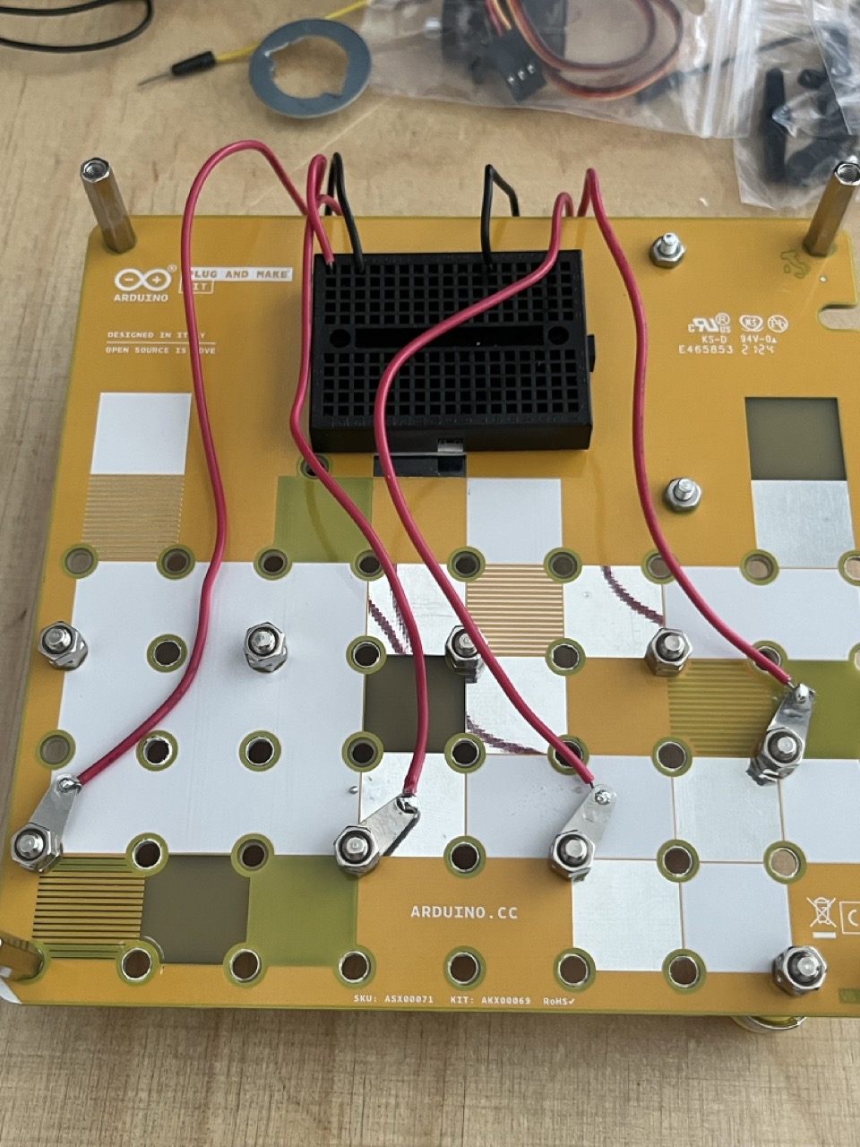
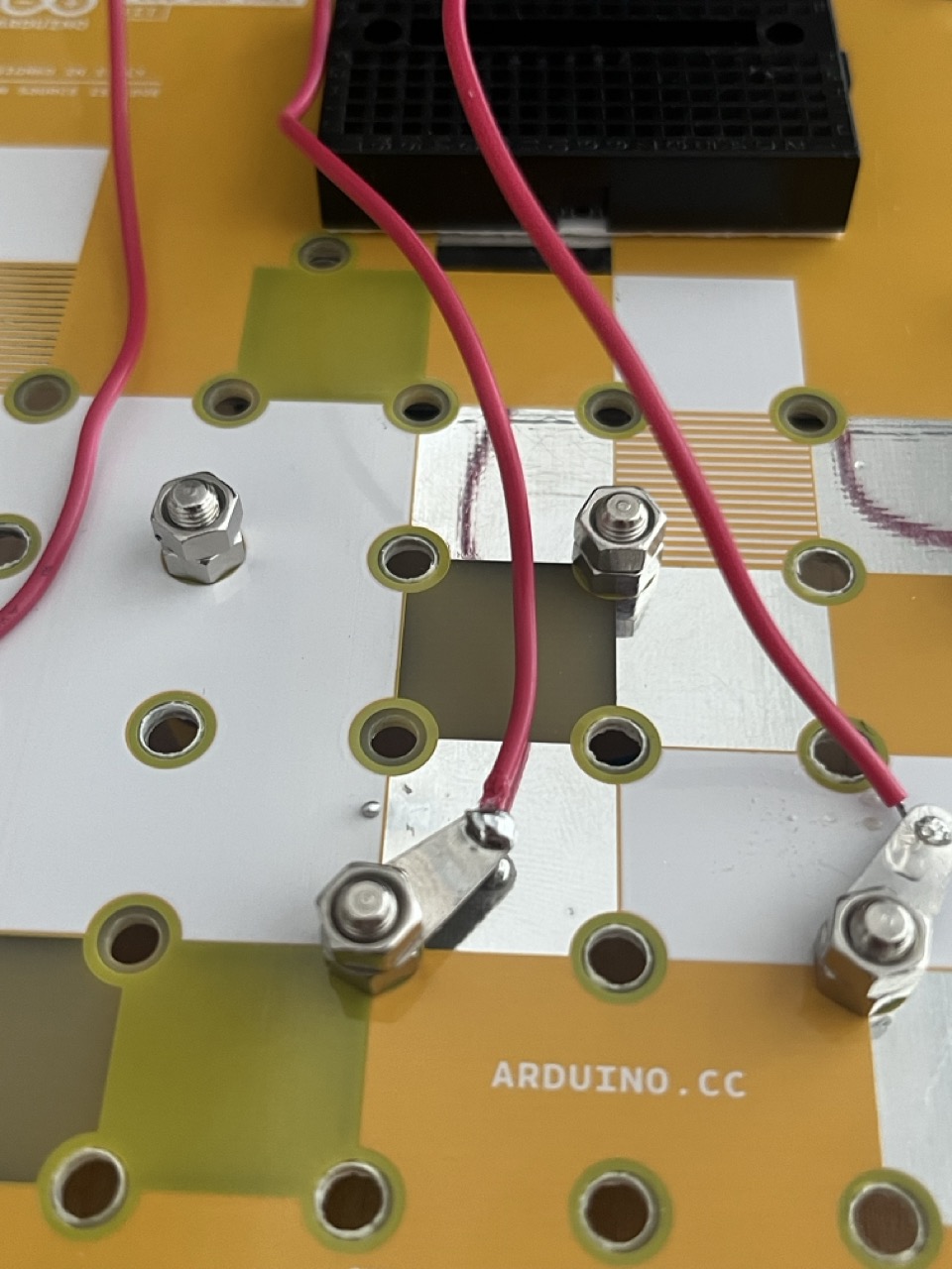
Place the bananas connector on the Modulino Base, and solder 4 cable for the banana connector that matches the words: OPEN , SOURCE , IS , LOVE.
Then connect OPEN and IS to the digital pins 11 and 12. Then connect SOURCE and LOVE to the digital pins 2, 3.

Upload the code: https://github.com/giulio93/RiddleTreasure/tree/main/Fuzzy_Letters
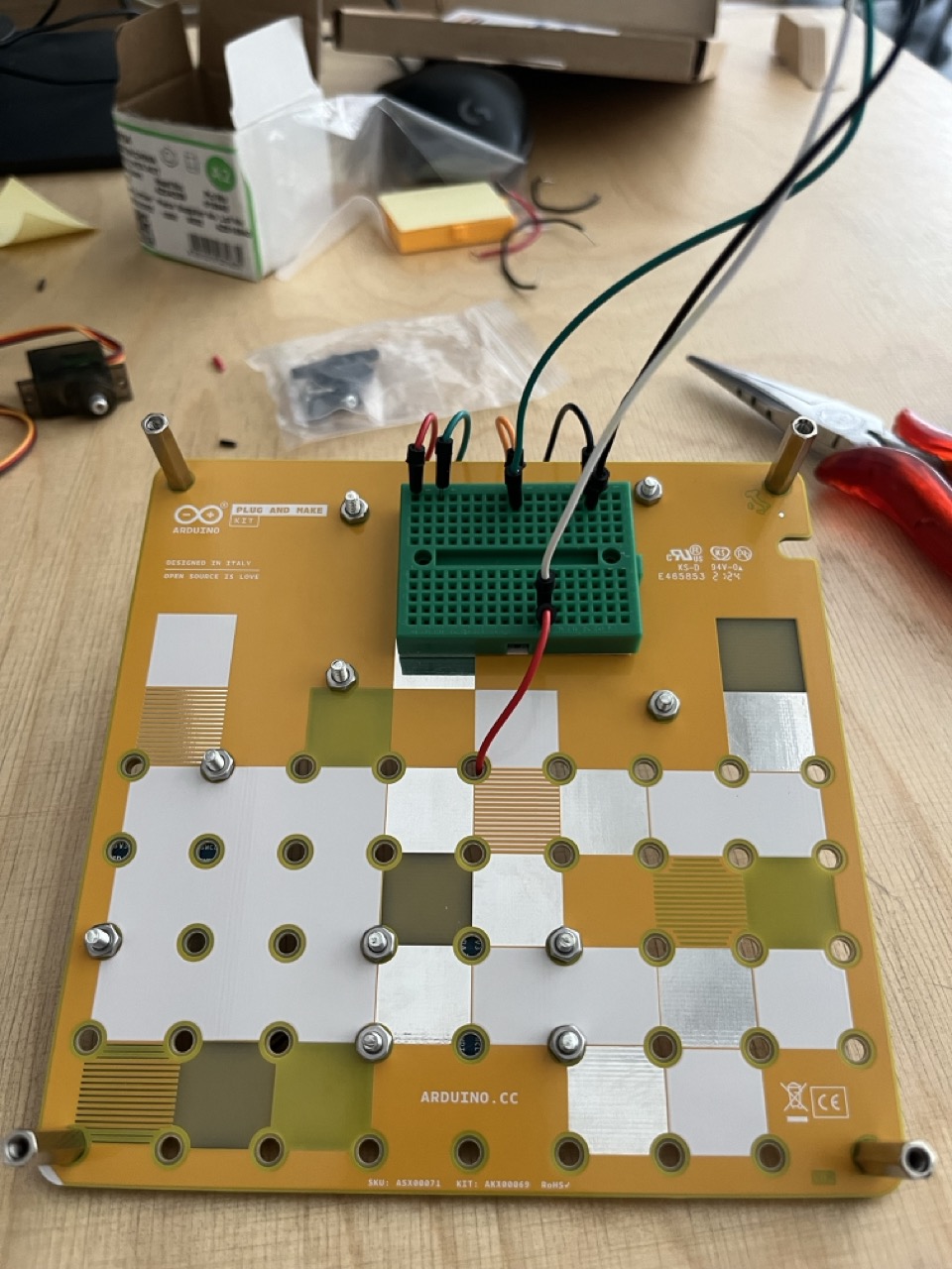
Password Pad & Servo Lock
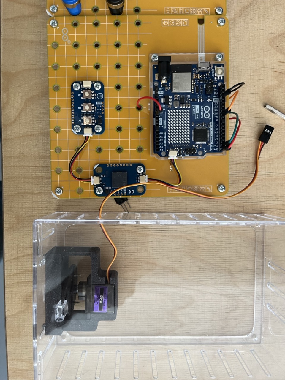
Let's build the last part, the servo lock.
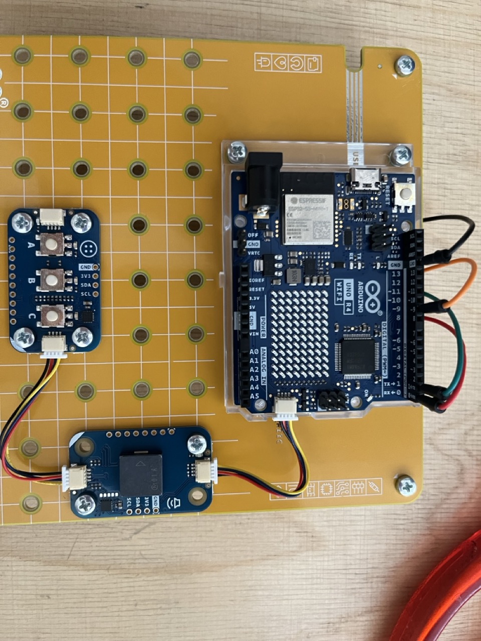
Connect the Modulino Buttons and Buzzer, to the Arduino UNO R4 WiFi using the Qwicc connectors.
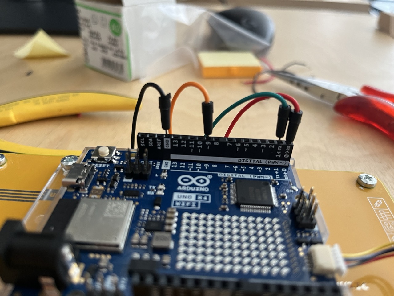
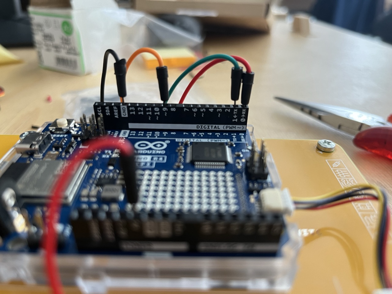
Use jumpers to connect TX,RX, GND, 5V, and digital pin 9 to the bread board on the back of the platform.
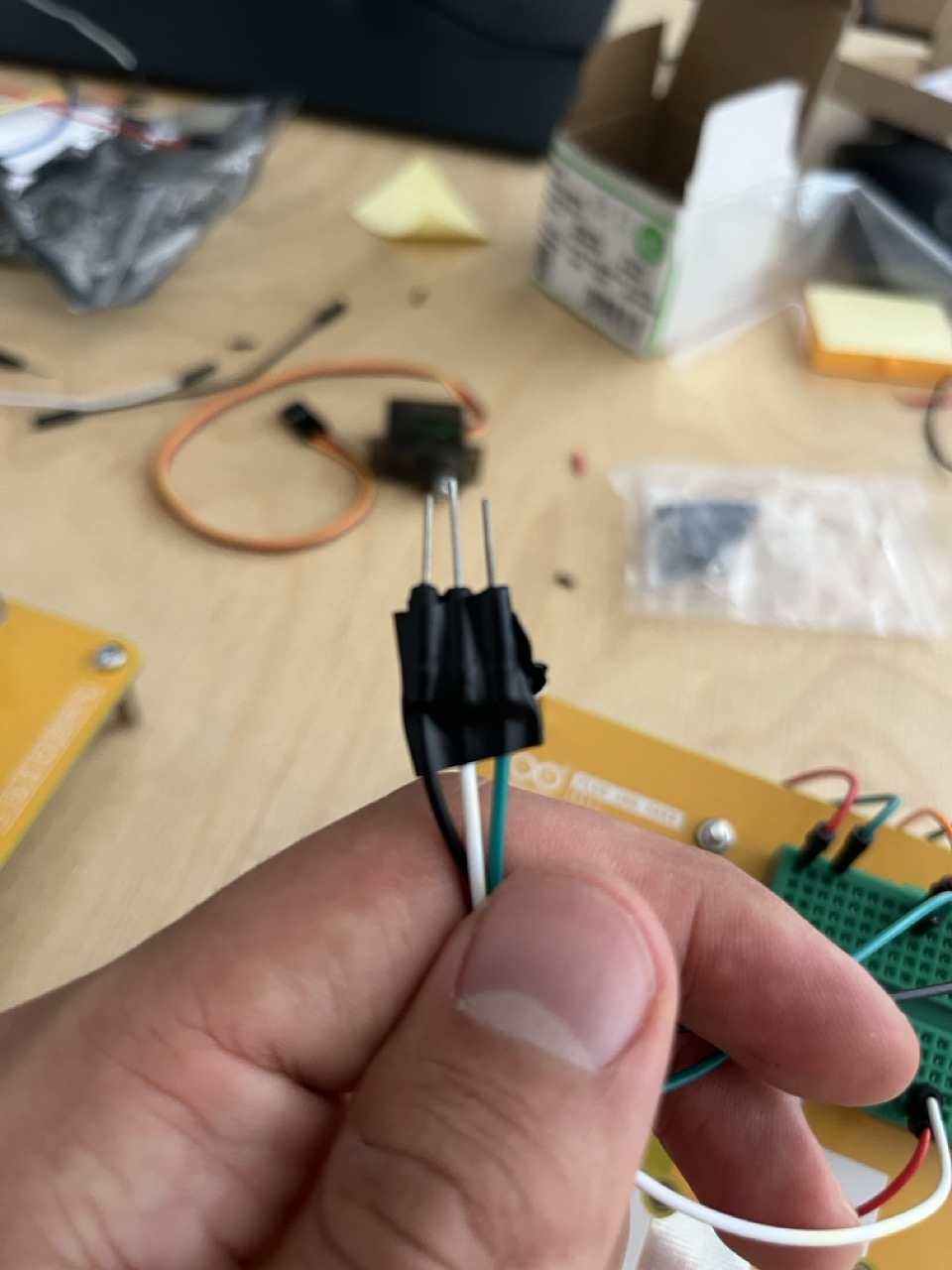
Let's create the motor connection for our servo lock: connect 3 more jumpers to the bread board taking signal from the 9 pin, GND e 5V.
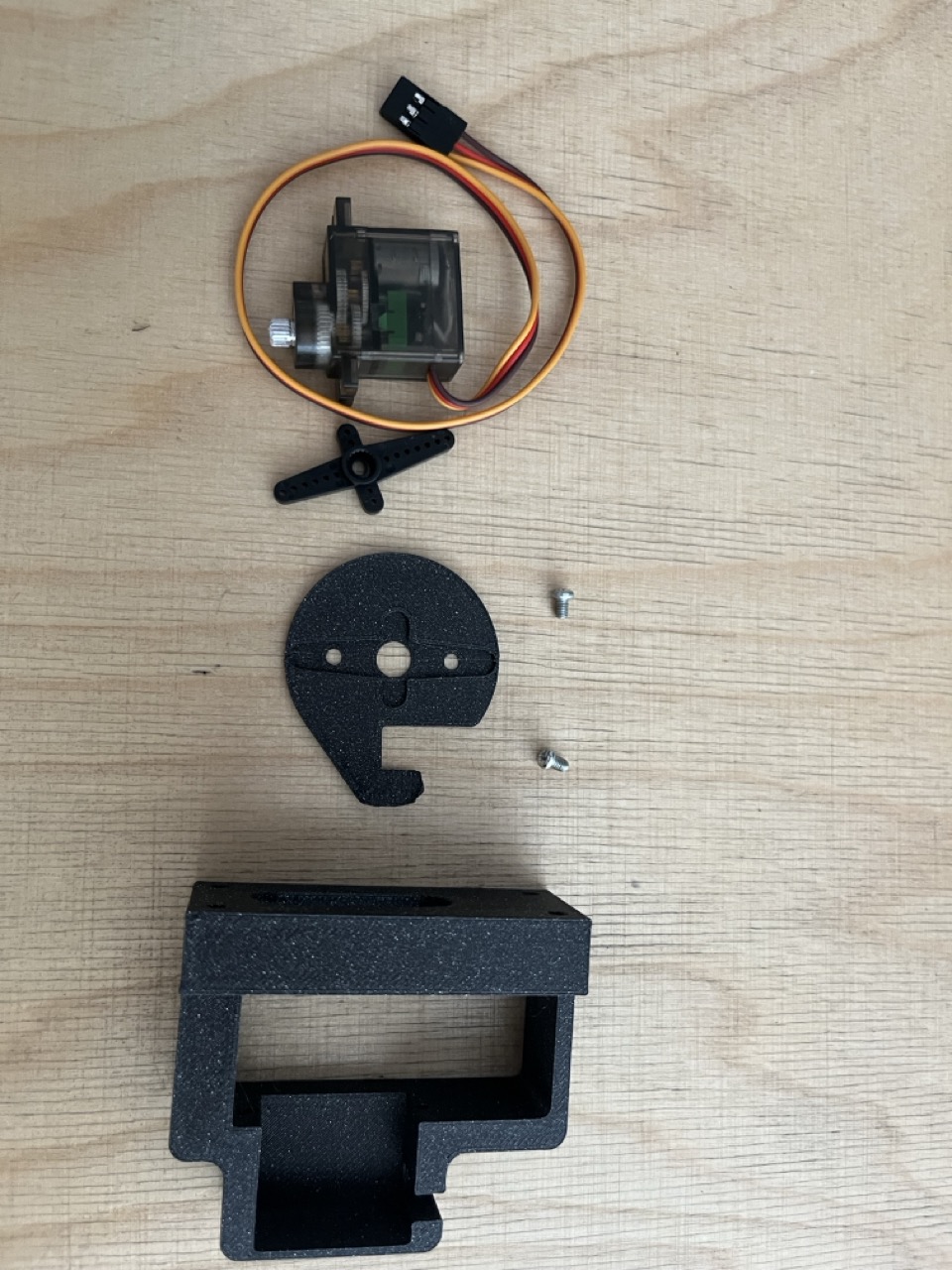
Servo Lock
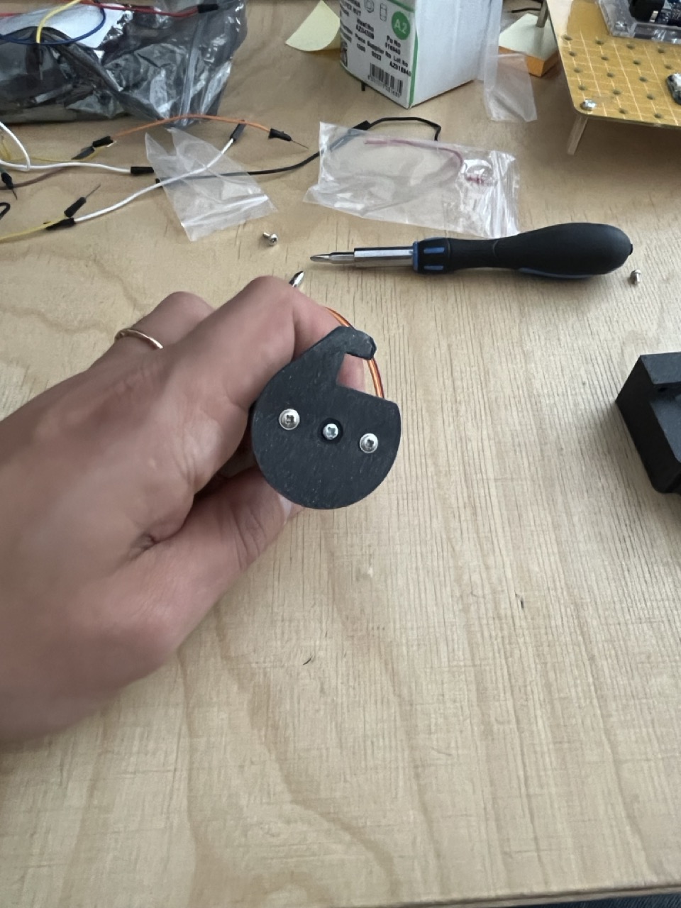
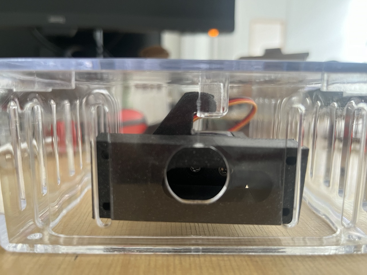
Assemble the servo with the 3d printed parts:
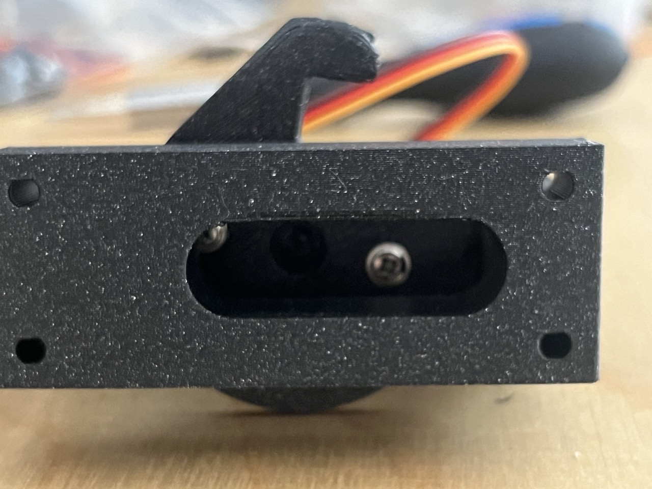
- Start from the motor lock
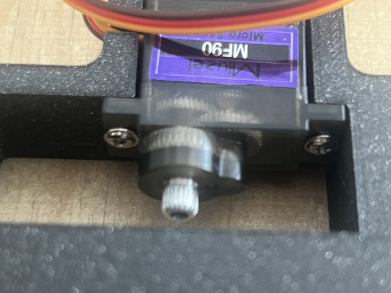
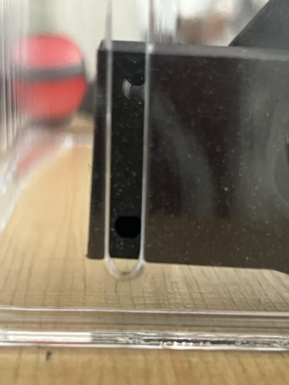
- Mount the motor holder with screws
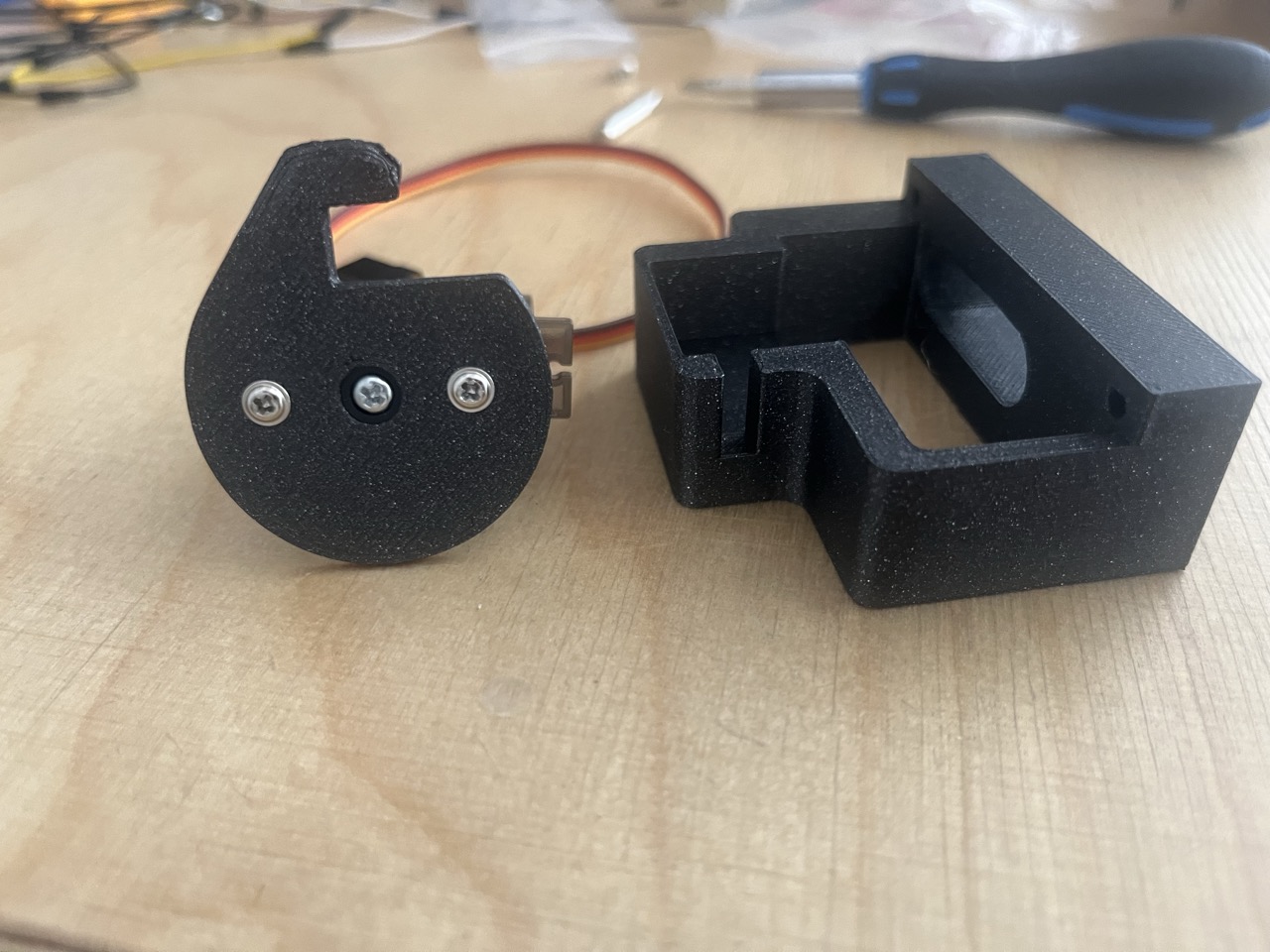
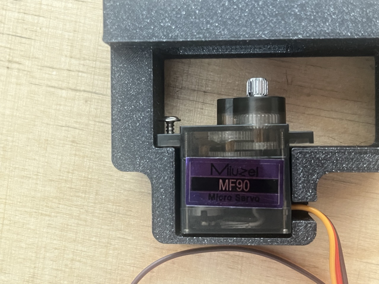
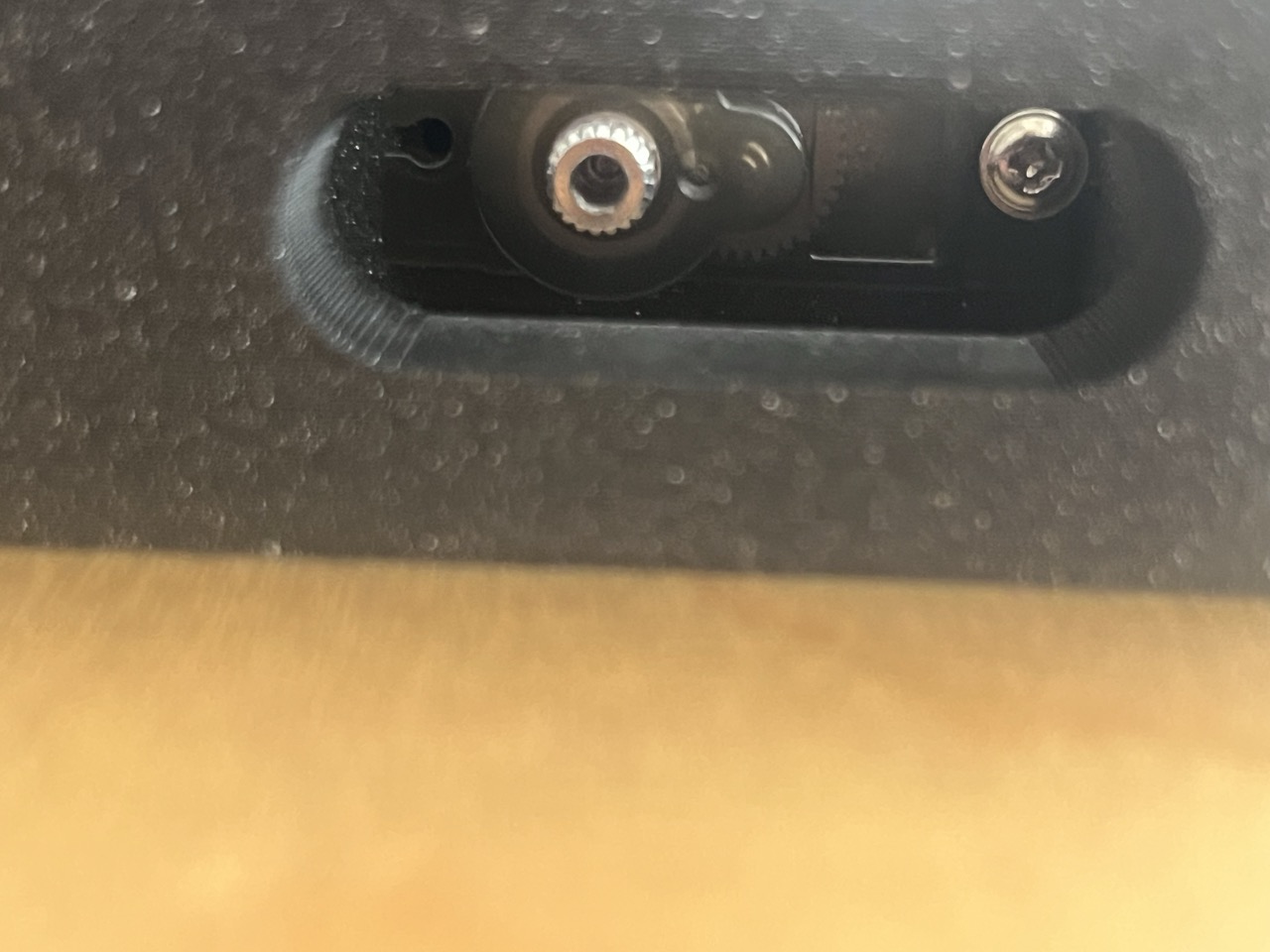
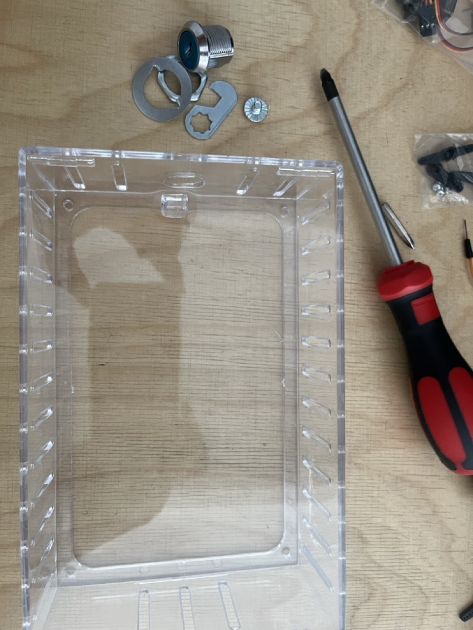
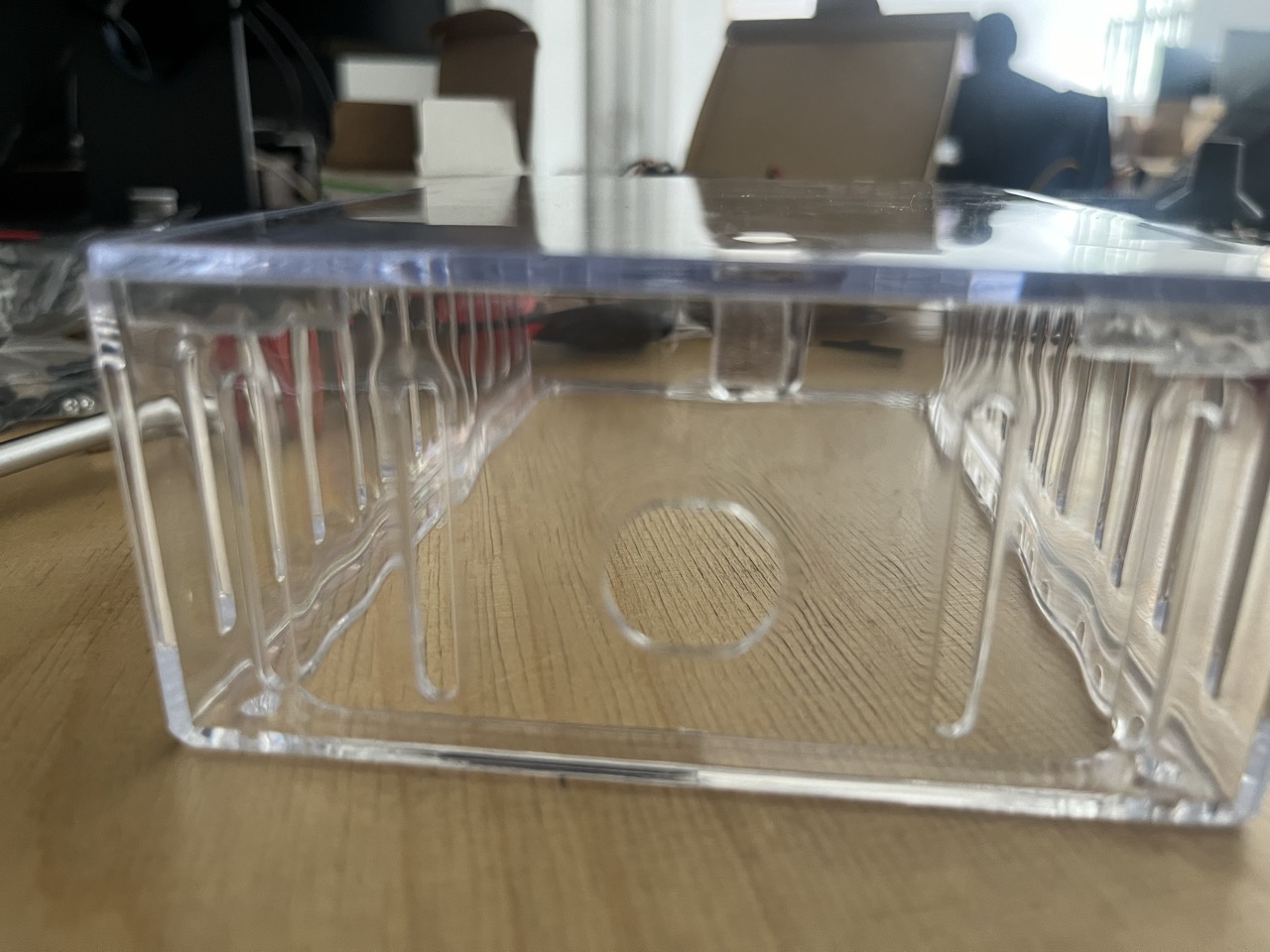
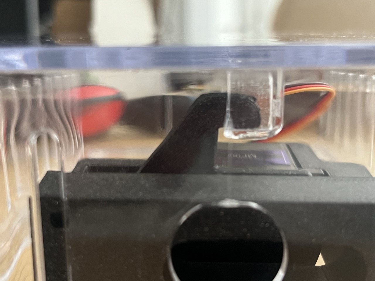
Let's take the plastic box and take out the original key lock: there is just one screw that allows you to take out the whole lock.
Align the motor to the lock so the box is closed, use the screw in the outer part of the motor holder to align the servo lock.
Upload the code: https://github.com/giulio93/RiddleTreasure/tree/main/Safe_Key_pad
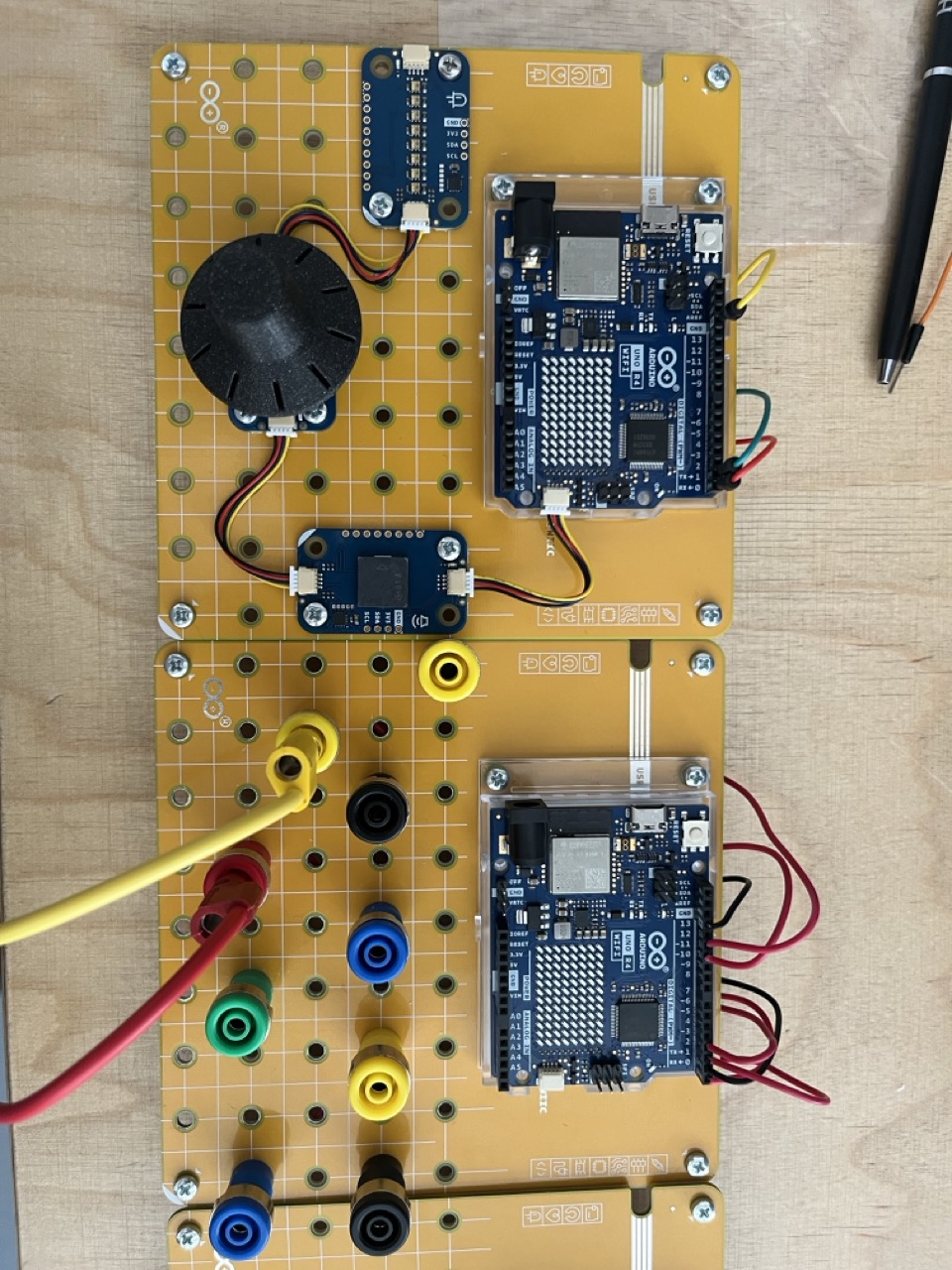
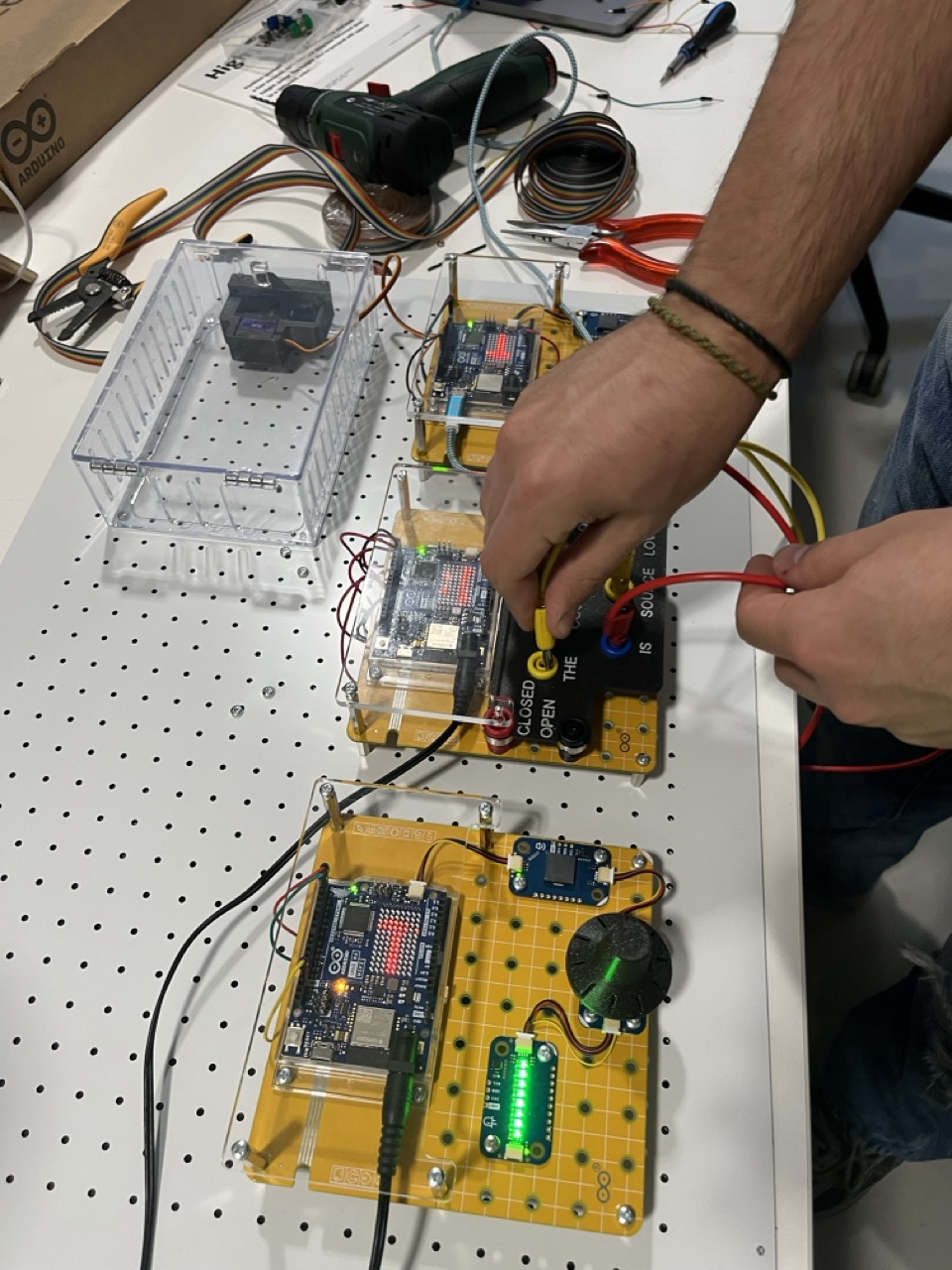
Wiring up all the Arduinos
Each Arduino UNO needs to communicate with the following one, creating a big state machine!
So the Rotary and Timer part will communicate via serial to the Banana Field that is again connected via Serial to the Password & Servo Lock part, that communicate back to the Rotary and Timer, closing the circuit.
This is quite simple yet optimal communication protocol in Arduino. We use TX and RX at the end of each Arduino board, software define as Serial1. In order to communicate each Arduino board needs to share the GND.
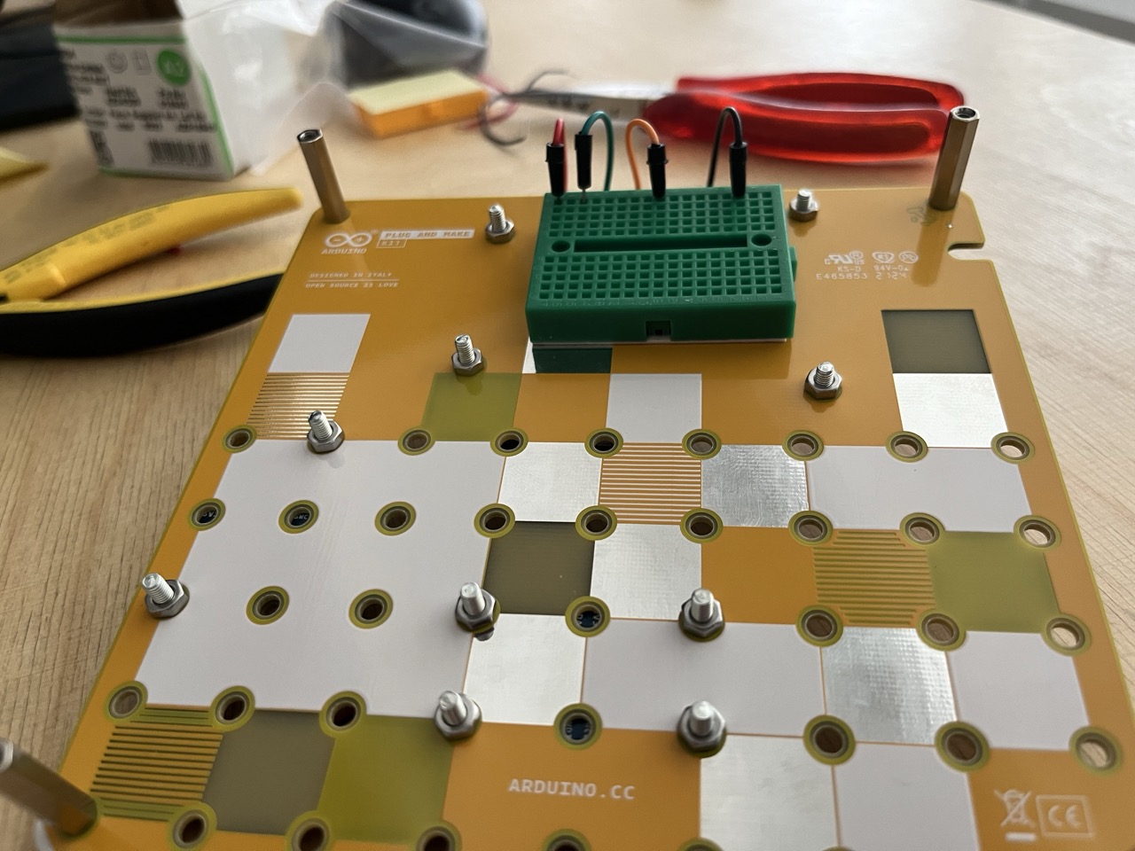
So i've actually use a bread board on the back of each panel, in order to tidy up and easily reach the TX,RX and GND of each Arduino board, than i wire up each board to the other using long jumpers connecting each bread board.
Interactive Escape Rooms: The Riddle Treasure Box
The Riddle Treasure Box is pure Dungeons-and-Dragons style puzzle design. It utilizes hidden sensors and arrays to track a "secret code" that takes the form of a physical action, like turning knobs to exact angles or pressing piano keys in a specific melody.
The Passcode Array Engine
Let's assume the lock requires sliding three potentiometers to exactly 10, 50, and 90.
- The Reading Phase: The Arduino constantly reads
analogRead(A0) / A1 / A2. - It maps the 1024 values to a tight 0-100 scale using
map(). - The Validation Loop:
Note: You must give the user a 'margin of error' (+/- 2 on the slider).if ((val1 > 8 && val1 < 12) && (val2 > 48 && val2 < 52) && (val3 > 88 && val3 < 92)) { UnlockSequence(); }
Actuating the Latch
When the UnlockSequence() runs, the physical lid must pop open.
- The Arduino commands a 5V relay.
- The relay fires 12V into an Electric Solenoid Lock, physically pulling a heavy metal deadbolt plunger back against a strong spring for 3 seconds.
- The lid, being spring-loaded, suddenly snaps open revealing the treasure!
Crucial Escape Room Hardware
- Arduino Nano: Easily hidden inside the wood chassis.
- 12V Solenoid Cabinet Lock.
- 5V Relay Module.
- Input Methods: Potentiometers, RFID MFRC522 scanners, or capacitive touch plates disguised as brass bolts on the outside of the box!
- A beautifully stained wooden treasure chest.