This is the second version of my rotary platform. I make videos for YouTube and needed something I could present my components and completed projects on. So I decided to build this thing! The first version was based on an Arduino, but I considered it as too expensive just for powering a stepper motor and setting its speed. So I went for the ATtiny13A which is much cheaper.
Technical Deep-Dive
This project is a comprehensive study in embedded cost-efficiency, AVR chip flashing, and Darlington-pair actuation.
- Minimalist Microcomputing (ATtiny13A):
- Resource Constraints: The ATtiny13A features only 1KB of Flash memory and 64 bytes of SRAM. This mandates highly optimized code. By stripping away the heavy Arduino bootloader and standard libraries, the firmware communicates directly with the I/O registers for maximum execution speed and minimal footprint.
- Architecture: Operating at 1.2MHz to 9.6MHz, the chip provides sufficient clock cycles to manage the phase-switching logic of a 4-step or 8-step sequence required for the stepper motor.
- Stepper Actuation Logic (ULN2003):
- Phase Sequencing: To rotate the shaft, the ATtiny energizes the stepper coils in a specific order (e.g., A -> AB -> B -> BC...). The ULN2003 Darlington Array acts as an electronic switch, allowing the low-power ATtiny pins to control the high-current (5V/500mA) coils of the motor.
- Inductive Kickback Protection: The ULN2003 includes integrated "Clamping Diodes," which safely dissipate the back-EMF generated when the motor coils are switched off, protecting the sensitive microcontroller logic from voltage spikes.
- Variable Speed ADC Mapping:
- The ATtiny reads the value from a 10k Ohm Potentiometer and applies a certain delay in the code to speed up or down the rotation. The firmware maps the analog 10-bit value (0-1023) to a
delayMicroseconds()variable, creating linear control over the RPM for "Slow-Pan" cinematic shots or "High-Speed" orientation shifts.
- The ATtiny reads the value from a 10k Ohm Potentiometer and applies a certain delay in the code to speed up or down the rotation. The firmware maps the analog 10-bit value (0-1023) to a
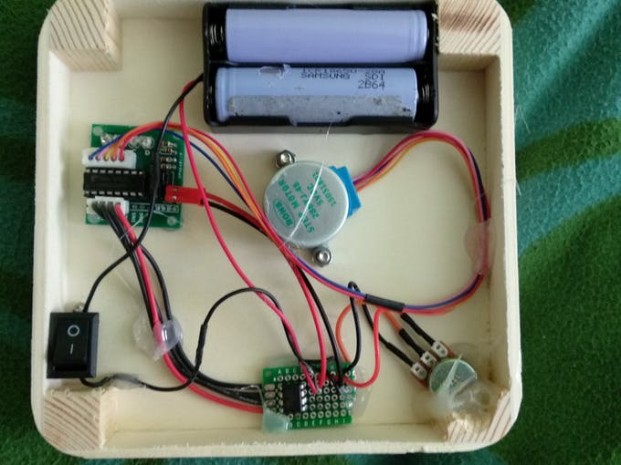
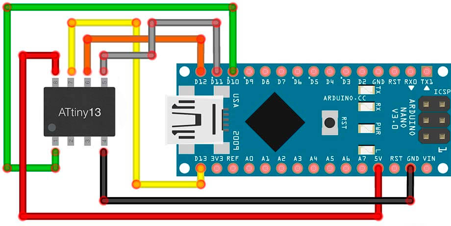
The electronics look the following:
Engineering & Construction
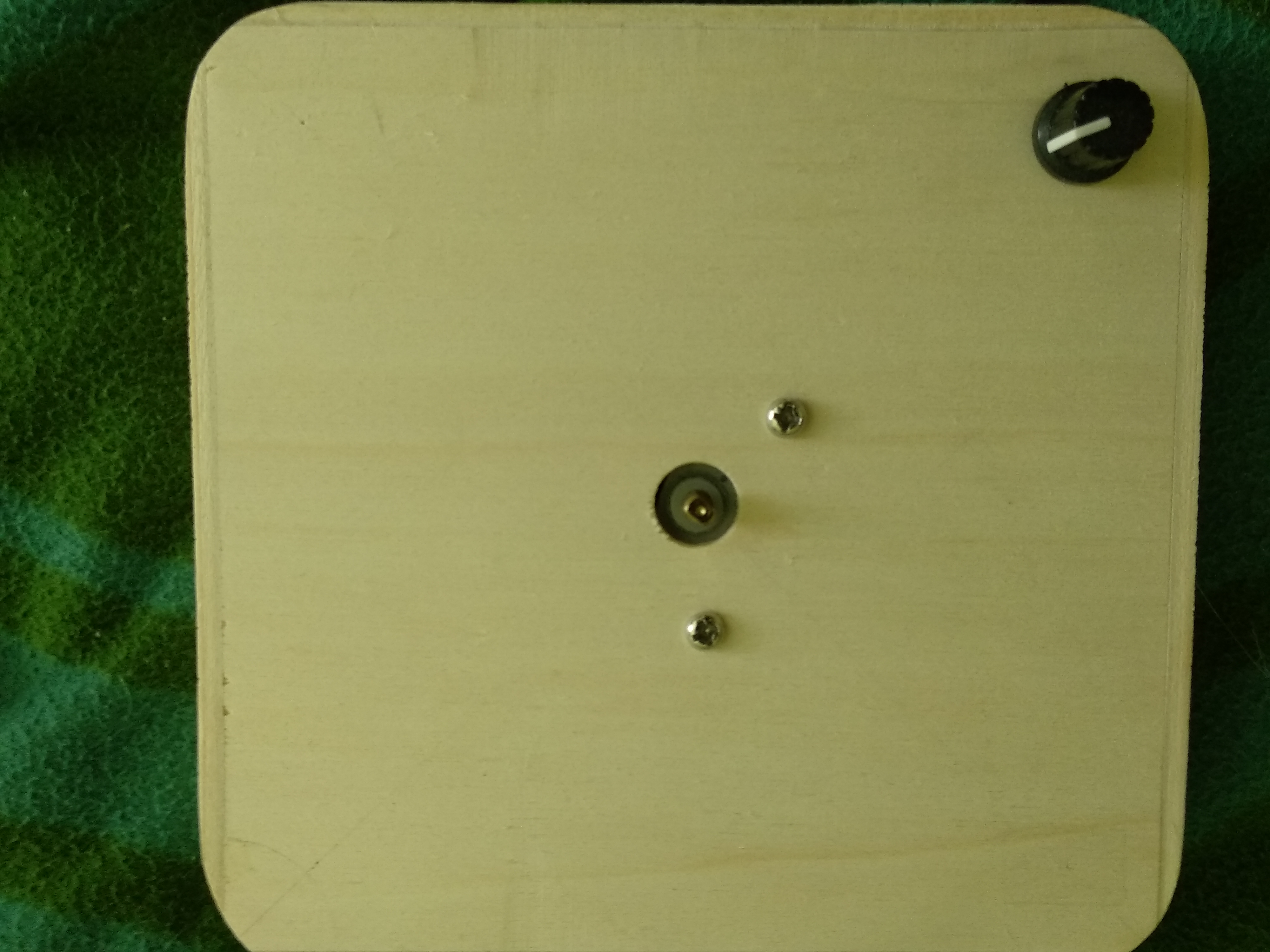
- Turntable Concentricity: The platform itself I printed on my Anet A8 and it is removable. The chassis includes a central mounting point designed for a snug fit on the 28BYJ-48 flat-shaft, ensuring minimal "wobble" or eccentricity during rotation—critical for macro photography.
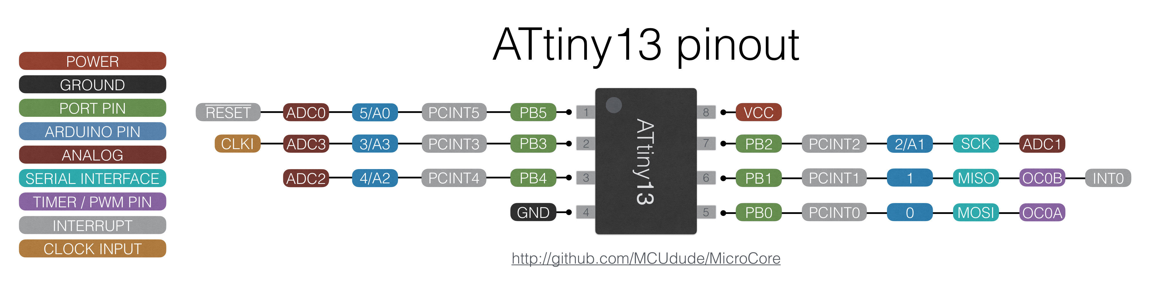
The pinout, just in case:
- Power Rail Stabilization & Modular Assembly: In the documentation, I note the danger of overvoltage. A refined version of this build should include a 5V Step-Down (Buck) Converter to ensure the motor and MCU receive a steady voltage, preventing the "skipping" of steps that occurs during brownouts. By using a removable 3D-printed top, the platform can be swapped for different diameters or mounting jigs, making it a versatile station for reviewing everything from tiny electronic components to larger hand-held devices.
- Production Utility: Beyond photography, this type of precision rotation is the foundation for 3D scanning rigs and scenery automation in miniature displays, proving that even a 1-dollar microcontroller can drive industrial-inspired results.
Please, watch this video about the building process:
If you liked it, please leave a like and comment on YouTube! I would really appreciate that :)
Elevate your product presentation: Precision motion control in a compact, cost-effective package.
PS: I applied a little bit too much voltage to the schematic, it would be good to add a buck converter...