This project consists of using Hall effect sensors to determine the turning direction and RPMs of a DC motor. In this case 2 motors at the same time.
With the use of external interruptions, the state of the sensors 1 of each pair is determined, and with this the state of the sensors 2 placed at four (90 degrees) is registered and by means of the code determine if the direction of rotation of each motor. In addition to internal interruptions (Timer1), the period time is calculated to determine the frequency (Turns per second) and the RPM of each motor.
On each motor shaft, I have improvised an encoder with neodymium magnets.
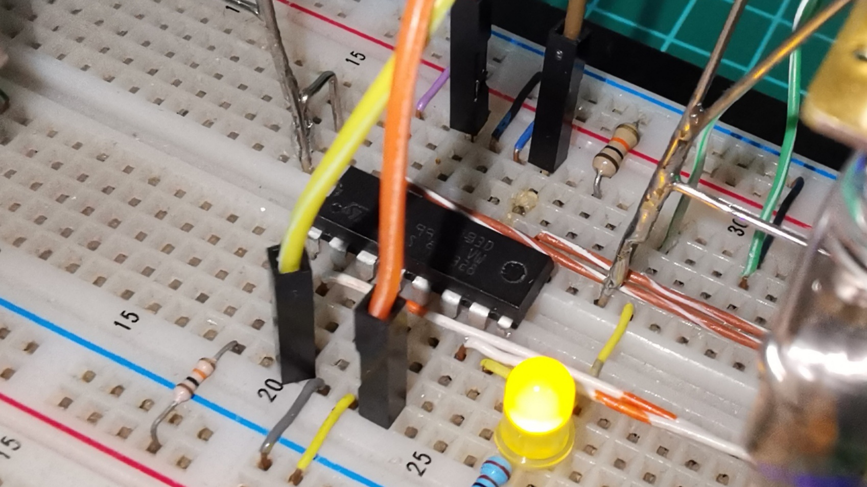
To control the direction of rotation of each motor, I use op amps (LM324N) with a joystick and a driver (L293N and L298N).
To digitize the analog signal from each sensor I use op amps as comparators.
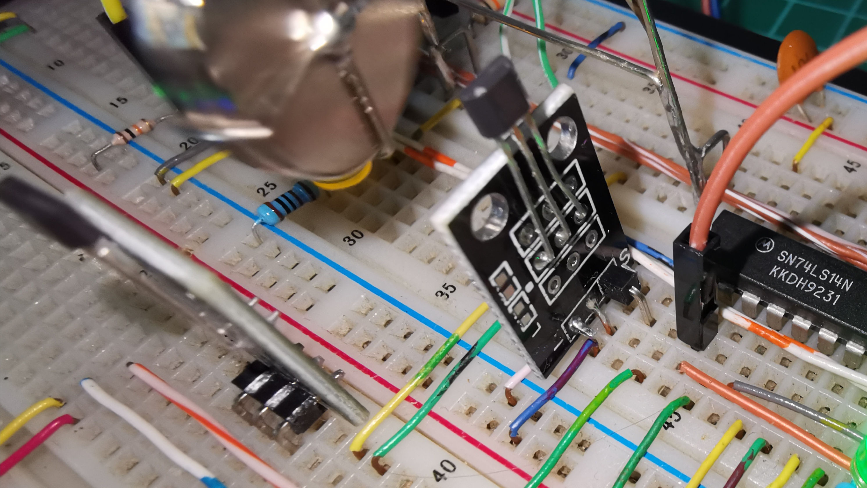
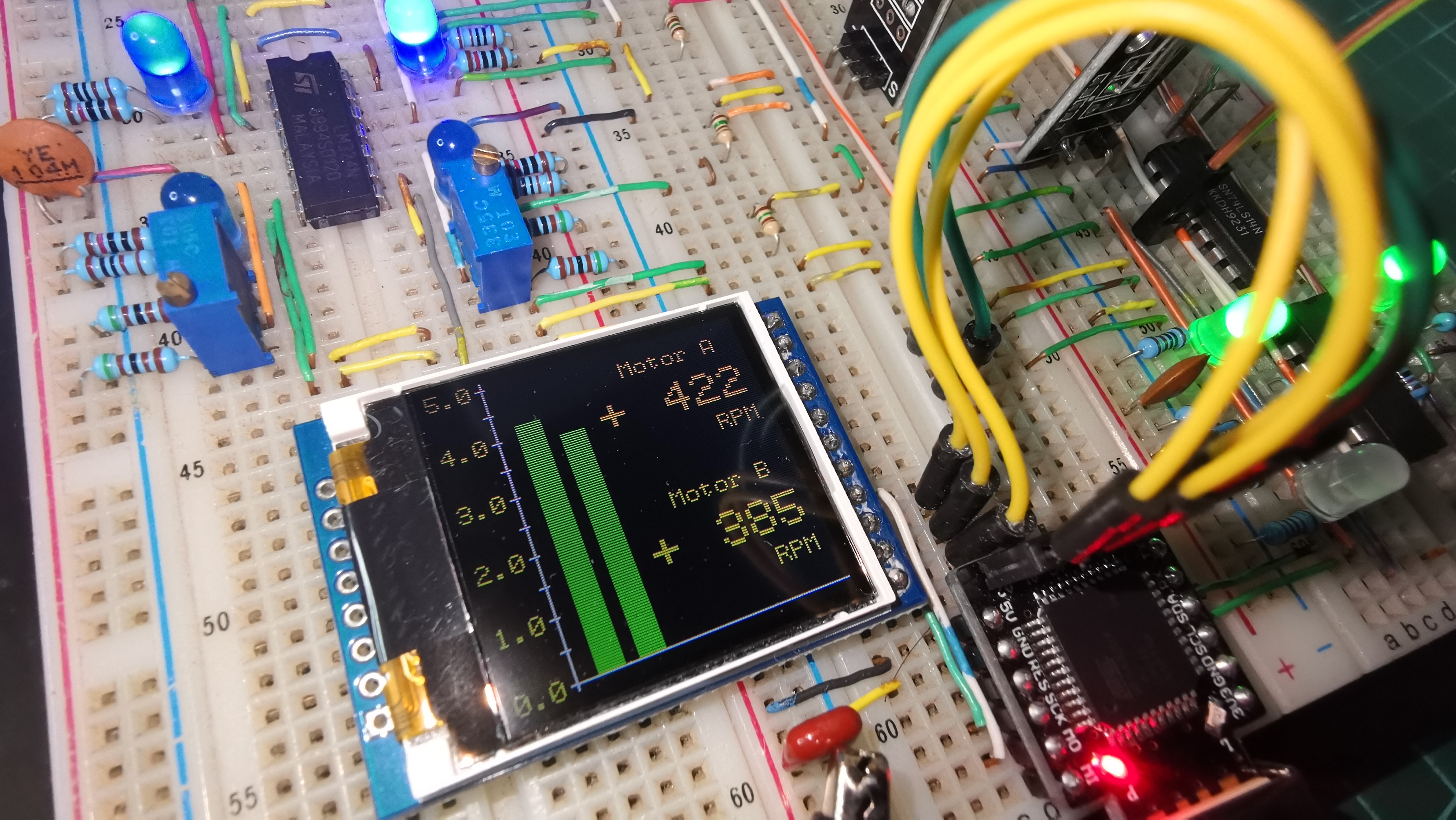
Last but not least, I have used a Schmitt Trigger Inverter (SN74LS14N) to nullify the transient effect of each sensor, thus avoiding false readings and thus obtaining with sufficient precision the revolutions and direction of rotation of each motor.
I use the ATmega32u4 (Beatle BadUSB) microcontroller as Arduino Leonardo, however the code is usable on most types of arduino.
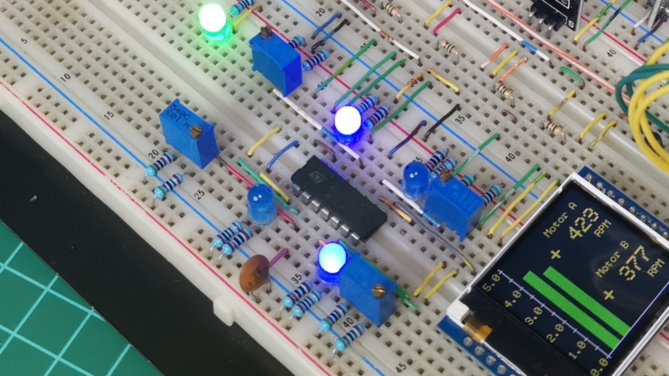
The display is a ST7735 of 128x128 pixels with SPI bus, easy to use.
Technical Deep-Dive
This project, "Mag-Tach," is a masterclass in Magnetic Sensing Forensics and Signal Integrity. While standard RPM meters use single-pulse IR sensors, this project utilizes a dual-channel Quadrature Hall Effect architecture. By mapping the magnetic flux of neodymium magnets through linear sensors and conditioning the signal with Schmitt triggers, Mag-Tach extracts both the scalar magnitude (RPM) and the vector direction (+/-) of two concurrent DC motors, providing high-fidelity telemetry for robotics and propulsion systems.
- Quadrature Encoding Forensics:
- The 90-Degree Phase Shift: Two Hall effect sensors (KY-035) are positioned at a 90-degree spatial interval relative to the magnetic poles, as shown in the first image. This creates two square waves (Channel A and B) that are phase-shifted.
- Vector Direction Logic: By monitoring which channel triggers its
FALLINGedge first, the ATmega32U4 determines the rotational vector. If A leads B, the motor is CW (+); if B leads A, the motor is CCW (-).
- Signal Conditioning & Noise Nullification:
- The Schmitt Trigger (SN74LS14N): Hall effect sensors often produce transient "jitter" at the edge of magnetic attraction. This project utilizes a Schmitt trigger with Hysteresis to digitize the analog signal. This ensures that the interrupt pins only see "Clean" square waves, eliminating false triggers caused by magnetic noise.
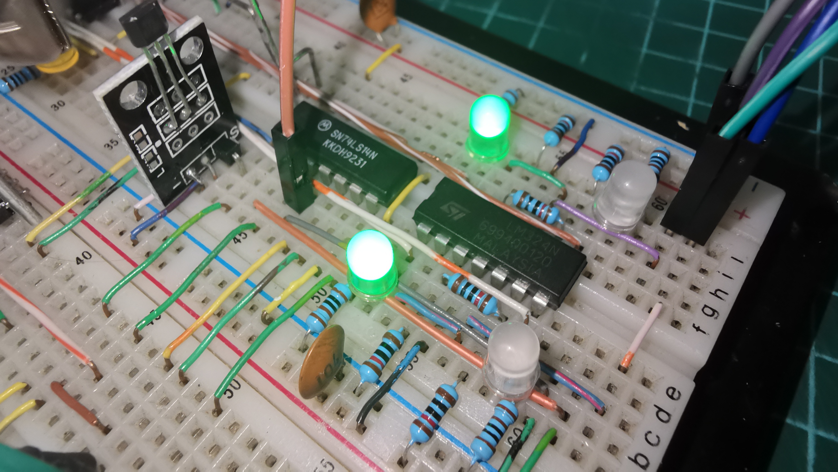
- Op-Amp Comparison: The LM324N, shown in the second image, serves as a high-speed comparator, transforming the linear analog voltage from the Hall sensors into logic-level transitions required by the Schmitt trigger.
- Timer1 Frequency Extraction:
- Period-Based Measurement: Instead of counting pulses per second (which is inaccurate at low RPM), Mag-Tach measures the time between pulses using the
TimerOnelibrary. By calculating the reciprocal of the period, the system achieves near-instantaneous RPM updates even during slow starts or rapid decelerations.
- Period-Based Measurement: Instead of counting pulses per second (which is inaccurate at low RPM), Mag-Tach measures the time between pulses using the
Engineering & Implementation
- Interrupt-Driven Architecture:
- High-speed tachometry requires non-blocking logic. The project utilizes
attachInterrupton pins 2 and 3 to handle the motor A/B pulses. This allows the primary CPU loop to focus on rendering the ST7735 TFT graphics while the hardware handles the millisecond-accurate timing in the background.
- High-speed tachometry requires non-blocking logic. The project utilizes
- Visual Data Analytics (ST7735):
- The 128x128 color display is utilized for Live Bar Graphs, as seen in the final image. The code maps the
rpmvalue to a visual Y-axis, providing a real-time analog-style representation of motor performance alongside the digital RPM readout.
- The 128x128 color display is utilized for Live Bar Graphs, as seen in the final image. The code maps the
- Atomic Data Protection:
- To prevent "Race Conditions" where the main loop reads a multi-byte variable while an interrupt is updating it, the code utilizes the
ATOMIC()block. This ensures data integrity by temporarily disabling interrupts during the RPM math calculation.
- To prevent "Race Conditions" where the main loop reads a multi-byte variable while an interrupt is updating it, the code utilizes the
Conclusion
Mag-Tach represents a significant leap in Propulsion Telemetry. By mastering the synthesis of Quadrature Phase Logic, Hysteresis-based Debouncing, and Atomic Data Management, developers can build industrial-grade encoders for mission-critical robotic platforms.
Vector Precision: Mastering rotational forensics through magnetic quadrature.
In the following video you can see the operation and testing of the code:
/*
RPM Meter Direction
Use Square Encoder with Hall effect sensors
By DrakerDG (c)
https://www.youtube.com/user/DrakerDG
*/
#include <SPI.h>
#include <TFT_ST7735.h>
#include <SimplyAtomic.h>
#include <TimerOne.h>
#define	 GREEN 0x07E0
#define YELLOW 0x07FF
#define DC A0 //9
#define RS A1 //10
#define CS A2 //11
// Sensor pins
const byte PinX[4] = {2, 3, 10, 11};
// Limit of microseconds
const long uSeg = 100000;
// Left position RPM labels
const byte x1 = 75;
// Pulse timer counters
volatile unsigned long pwc[2];
// PWM periods
volatile unsigned long pwm[2];
// RPM values
unsigned long rpm[2];
// States of the second sensors
volatile bool Sen[2];
// Count variable printing millis
unsigned long prT = 0;
TFT_ST7735 tft = TFT_ST7735(CS, DC, RS);
void CountSA(void);
void CountSB(void);
void RPMc(void);
void Draw_Table(void);
void Print_Data(void);
void setup(){
 Serial.begin(9600);
 tft.begin();
 tft.setRotation(1);
 tft.clearScreen();
 tft.setTextWrap(true);
 tft.setTextColor(YELLOW, BLACK);
 tft.setCursor(0, 0);
 Draw_Table();
 for (byte i=0; i<4; i++){
   pinMode(PinX[i], INPUT);
   }
 for (byte i=0; i<2; i++){
   pwc[i] = uSeg;
   pwm[i] = uSeg;
   rpm[i] = 0;
 }
 // Interrupt to count period time
 Timer1.initialize(100);
 Timer1.attachInterrupt(RPMc);
 // Interrupt of Sensor 1 of Motor A
 attachInterrupt(digitalPinToInterrupt(PinX[0]), CountSA, FALLING);
 // Interrupt of Sensor 1 of Motor B
 attachInterrupt(digitalPinToInterrupt(PinX[1]), CountSB, FALLING);
}
void loop(){
 Print_Data();
}
void CountSA(){
 // 2nd sensor value
 Sen[0] = 1 & (PINB >> 7);
 pwm[0] = pwc[0]; // Save the period
 pwc[0] = 0; // Reset the timer
}
void CountSB(){
 // 2nd sensor value
 Sen[1] = 1 & (PINB >> 6);
 pwm[1] = pwc[1]; // Save the period
 pwc[1] = 0; // Reset the timer
}
void RPMc(){
 for (byte i=0; i<2; i++){
   // Increase the time counter
   pwc[i]++;
   if (pwc[i] > (uSeg)){
     // Limit the timer & period
     pwc[i] = uSeg;
     pwm[i] = uSeg;
   }
 }
}
void Draw_Table(){
 // Code to draw the table on screen
 tft.drawFastVLine(22, 0, 128, WHITE);
 for ( int i=0; i<11; i+=1 ){
   tft.drawFastHLine( 20, 5+i*12, 4, WHITE);
   if (!(i&1)){
     tft.setCursor( 0, i*12 + 2);
     tft.print((10.0-i)*0.5, 1);
     }
   }
 tft.drawFastHLine( 20, 125, 128, WHITE);
 tft.setTextSize(1);
 tft.setCursor(x1, 10);
 tft.print("Motor A");
 tft.setCursor(x1+30, 45);
 tft.print("RPM");
 tft.setCursor(x1, 70);
 tft.print("Motor B");
 tft.setCursor(x1+30, 105);
 tft.print("RPM");
 tft.setTextSize(2);
}
void Print_Data(){
 unsigned long nwT = millis();
 // Calculations and prints every 10ms
 if ((nwT - prT) > 10){
   prT = nwT;
   char sRPM[10];
   for (byte i=0; i<2; i++){
     //RPM
     tft.setCursor(x1, 25+60*i);
     // Protects math calculation
     ATOMIC()
     {
       // Detect Rotation Decrease
       if (pwc[i]>(pwm[i]*2)){
         pwm[i] *= 2;
         pwm[i] = constrain(pwm[i], 0, uSeg);
         pwc[i] = pwc[i]*2;
       }
       /* detects or not the
       rotation of the motors */
       if (pwm[i] < uSeg) rpm[i] = 6*uSeg/pwm[i]; // Detects rotation
       else if ((rpm[i] > 0)&&(pwm[i] == uSeg)) rpm[i] = int(rpm[i]/2); // No rotatiom
       // Limits the value of RPMs
       rpm[i] = constrain(rpm[i], 0, 9999);
     }
     dtostrf(rpm[i], 4, 0, sRPM);
     // Print the RPMs
     tft.print(sRPM);
     int valX = rpm[i]*120/500;
     // Prints the RPM bars
     tft.fillRect(30+15*i, 0, 10, 125 - valX, BLACK);
     tft.fillRect(30+15*i, 125 - valX, 10, valX, GREEN);
     tft.setCursor(x1-15, 25+60*i);
     /* Determines the direction
     of rotation of the motors.
     Prints + if it turns CW and
     - if it turns CCW */
     if ((rpm[i] == 0)&&(pwm[i] == uSeg)) tft.print(" ");
     else if (Sen[i]) tft.print("-");
     else tft.print("+");
     }
   }
}