The main features could be the following:
- Access to a network wifi to control the device from a Blynk app
- Access to Blynk servers to ensure the time of the device was always on time
- Timers to sound the bell ring each change of class
- Schedule holidays and weekends to prevent the ring bell from ringing
- It doesn´t use batteries to maintain the configuration because it is stored in the Blynk servers
I hope you like.
Step 1: The Blynk App
Blynk is a IoT platform to connect your devices to the cloud.
To use it you have to do the following:
- Download and install Blynk app for Android or iOS.
- Create a new project and choose the ESP8266 device.
- You will receive by email an Auth Token for every device you have to include in the ESP8266 sketch later.
The steps I have followed to create this Blynk app has been the following:
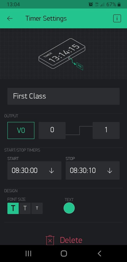
STEP 1
Add a timer for each change of class.
On each timer you specify the time when the ring bell must begin to sound and the time when it must stop.
I have associated the virtual pins V0, V1, V2... to each timer.
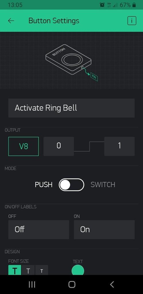
STEP 2
Add a push button to manually activate the ring bell.
I have associated the virtual pin V8 to this button.
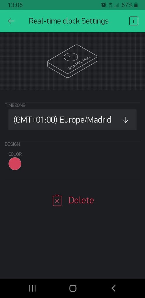
STEP 3
Add a real-time clock to get time from server and control the days the ring bell have to work.
Step 2: The ESP8266 Sketch
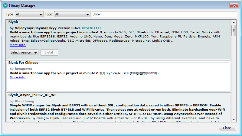
The sketch uses the following libraries:
- Blynk libraries. Go to library manager, search for Blynk and install it.
- TimeLib library. Go to the following link https://github.com/PaulStoffregen/Time and download the zip version. Go to Sketch -> Include Library -> Add.zip library, and select the previous zip file.
In the sketch we can highlight the following:
- The credentials to connect to Blynk server
#define BLYNK_PRINT Serial
#include <esp8266wifi.h>
#include <blynksimpleesp8266.h>
#include <timelib.h>
// You should get Auth Token in the Blynk App.
// Go to the Project Settings (nut icon).
char auth[] = "your device Auth Token";
// Your WiFi credentials.
// Set password to "" for open networks.
char ssid[] = "your wifi ssid";
char pass[] = "your wifi passwd";
SimpleTimer timer;
WidgetRTC rtc;
- The virtual pins (V0 to V8) associated to each change of class
BLYNK_WRITE(V0) {
\tif (param.asInt() == 1) SoundRingBell(1);
  \telse SoundRingBell(0);
 }
BLYNK_WRITE(V1) {
  \tif (param.asInt() == 1) SoundRingBell(1);
  \telse SoundRingBell(0);
 }<br>
- The procedure "SoundRingBell" where I have implemented the days where the ring bell must not work: the weekends and during July and August. The IO0 has been associated to control the ring bell.
void SoundRingBell(int value) {
\t// Not work on Sunday or Saturday
  \tif ((weekday() == 1) or (weekday() == 7)) return;
\t// Not work on July and August
  \tif ((month() == 7) or (month() == 8)) return;

  \tif (value == 0) digitalWrite(0,LOW);
  \telse digitalWrite(0,HIGH);
}
Step 3: How to Upload the Sketch to the ESP8266 Module
The steps to program the ESP8266 module using the ARDUINO IDE are the following:
STEP 1
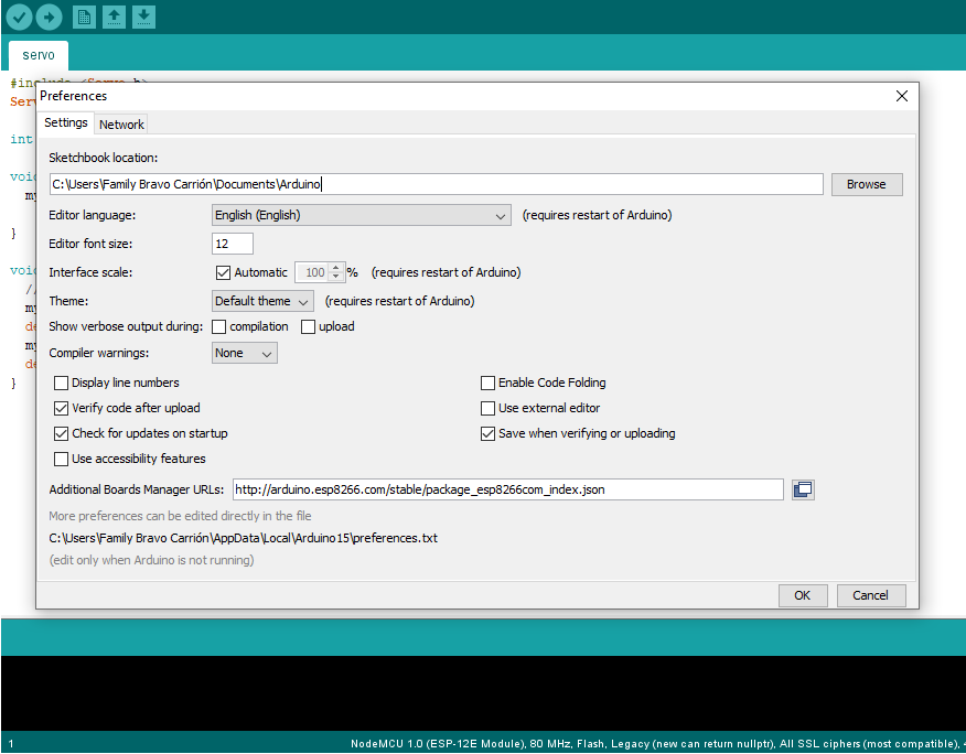
Open the preferences window from the ARDUINO IDE. Go to File->Preferences and enter
"http://arduino.esp8266.com/stable/package_esp8266com_index.json"
into Additional Board Manager URLs field.
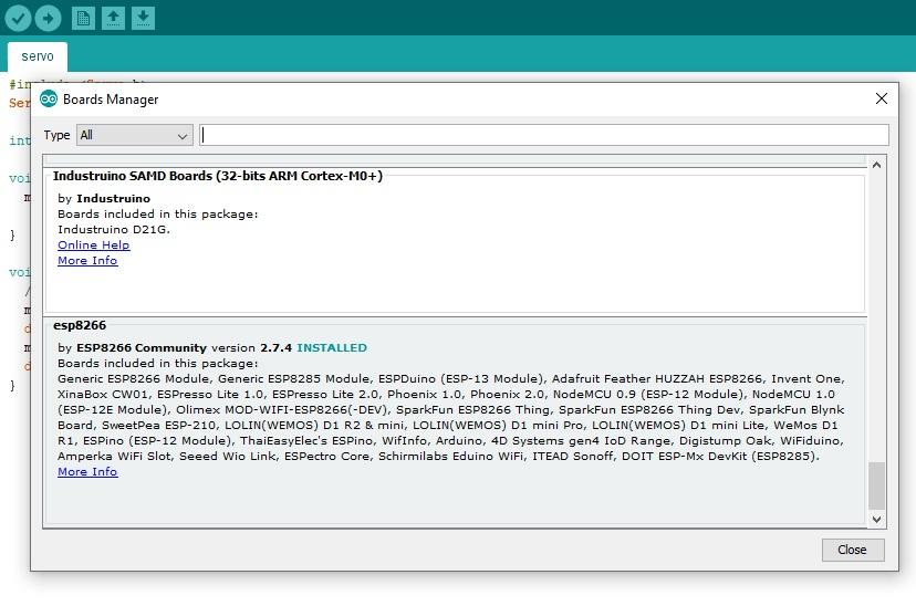
STEP 2
Go to Tools -> Board -> Boards Manager...
Select the ESP8266 board menu and install “esp8266”
STEP 3
Choose Tools > Board > Generic ESP8266 Module.
STEP 4
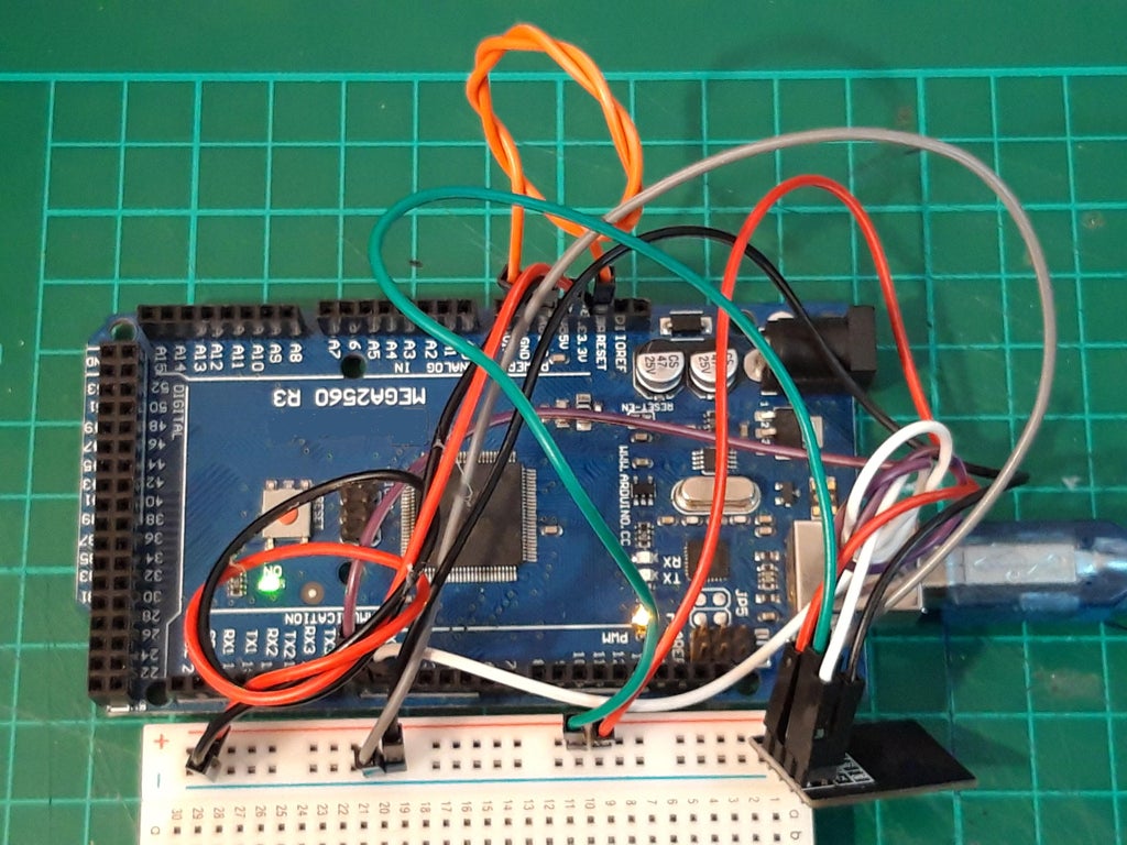
To upload a sketch to the ESP8266, I have used an ARDUINO MEGA 2560 module, although you can use an ARDUINO NANO or an ARDUINO UNO module.
Make the following connections between the ESP8266 and the ARDUINO MEGA 2560 modules:
- Connect the "3V3" pin to the "3V" pin in the ARDUINO MEGA 2560 module
- Connect the "RX" pin to the "RX/0" pin
- Connect the "EN" pin to the "3V" pin
- Connect the "IO0" pin to the "GND" pin
- Connect the "GND" pin to the "GND" pin
- Connect the "TX" pin to the "TX/1" pin
The last connection is the following: connect the "RESET" pin to the "GND" pin in the ARDUINO MEGA 2560. In that way, it will act as a communications gateway.
STEP 5
Select the communications port where the ARDUINO MEGA 2560 is connected and upload the sketch
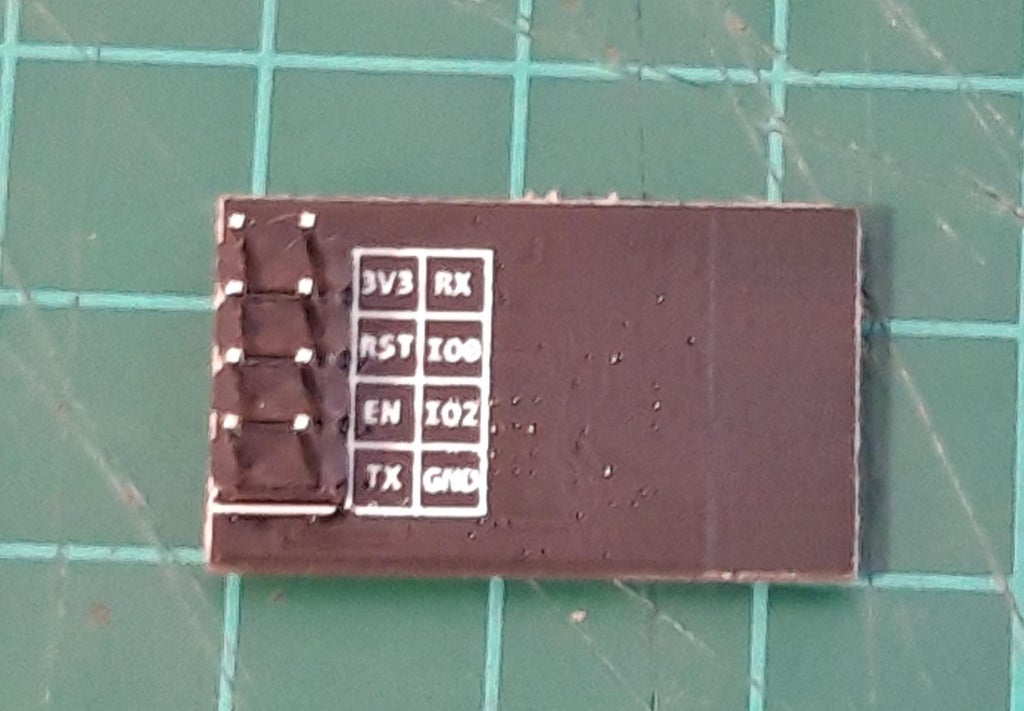
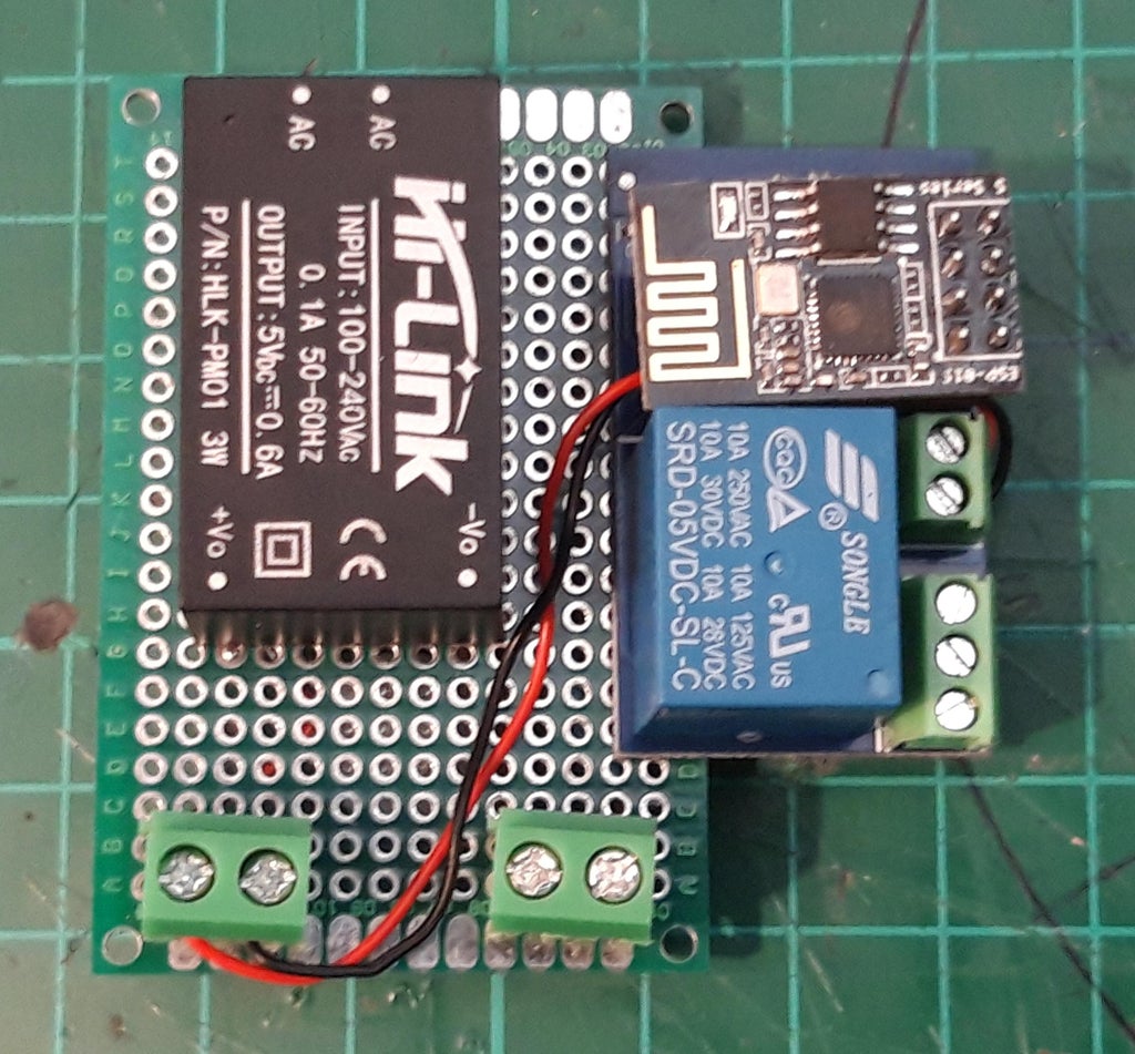
Step 4: The Device
The device is formed by a ESP-01 module and a relay everything integrated in a board. The ESP-01 module has two digitals I/O pins: IO0 and IO2 to activate the relay.
The board need 5V to work, as you can see in the image, so it need an 100-240 VAC to 5 VDC module
o control the ring bell, I have used the normally open (NO) pin of the relay
EXPANDED TECHNICAL DETAILS
Automated Educational Scheduling Hub
This project provides a robust solution for automating the daily bell cycles in schools or offices, replacing manual switches with a precise, IoT-enabled timer.
- Blynk Cloud-Scheduler Integration: Uses the Blynk IoT platform to provide a global scheduling interface. Administrators can set multiple bell times for "Class Start," "Recess," and "Dismissal" directly from a smartphone app.
- High-Current Solenoid Actuation: The Arduino (WiFi enabled) manages a heavy-duty industrial bell or siren via a high-current solid-state relay (SSR). The firmware ensures the bell rings for a precise duration (e.g., 5 seconds) regardless of network latency.
Reliability
- Local Time-Cache Buffer: The Arduino caches the daily schedule from the cloud; if the WiFi goes down, the internal RTC (Real-Time Clock) ensures the bells continue to ring accurately on schedule.