Physics in Action: The Balancing Robot
The Self-Balancing Robot is a hallmark project of robotics engineering. Operating on the principle of an "Inverted Pendulum," the robot is inherently unstable and will fall over unless the Arduino actively drives the wheels forward or backward to correct its lean.
The Sensor Fusion (IMU)
The robot relies on the MPU6050 (a 6-axis gyroscope and accelerometer).
- Accelerometers are noisy and susceptible to vibration. Gyroscopes drift over time.
- The Filter: You must use a software algorithm (like a Kalman Filter or a Complementary Filter) to fuse both sensor readings into a single, perfectly stable, rock-solid angle measurement (e.g., Pitch).
The PID Controller Loop
Once you know the robot is leaning 3 degrees forward:
- The Proportional/Integral/Derivative (PID) math determines exactly how much PWM power to send to the motors.
- The
L293Dmotor driver pulses 12V to the motors, driving the wheels forward to push the chassis back underneath its center of gravity. - This loop must run at least 100 times per second to prevent falling!
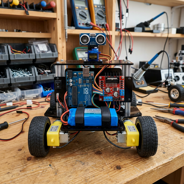
Hardware Components
- Arduino Uno: The brain.
- MPU6050 Sensor: The balance organ.
- L293D or L298N Motor Driver: The muscle interface.
- High RPM DC Gear Motors with Encoders: Standard yellow toy motors are usually too sloppy. You need motors with precise gearboxes.
Tuning the P, I, and D variables by trial and error is one of the most frustrating but immensely satisfying challenges in electronics.