Overview

On switching on power, our station in standby mode. It is mean that heater do not connected and you can see iron handle current temperature on LED display.
To start working need a long press on button 3 (Mode/ Standby). After this station enters to last working mode stored in EEPROM memory.
There is two working mode named "CLASS 1" and "CLASS 2".
CLASS 1 is temperature control working mode. It is possible to set desired temperature by two buttons 1 and 2 (UP and DOWN). Short press change units for 1 and long press for 5. These values you can change in sketch file:
const byte pinHeater = 2;   //pin for irf520 module
const uint16_t minTemp = 50;//temperature minimum
const uint16_t maxTemp = 700;//temperature maximum
const uint16_t measInterval = 500; //measurement interval ms. over 500
const byte shortPressStep = 1; //temperature step on button's short press
const byte autoPressStep = 5; //temperature step on button's long press
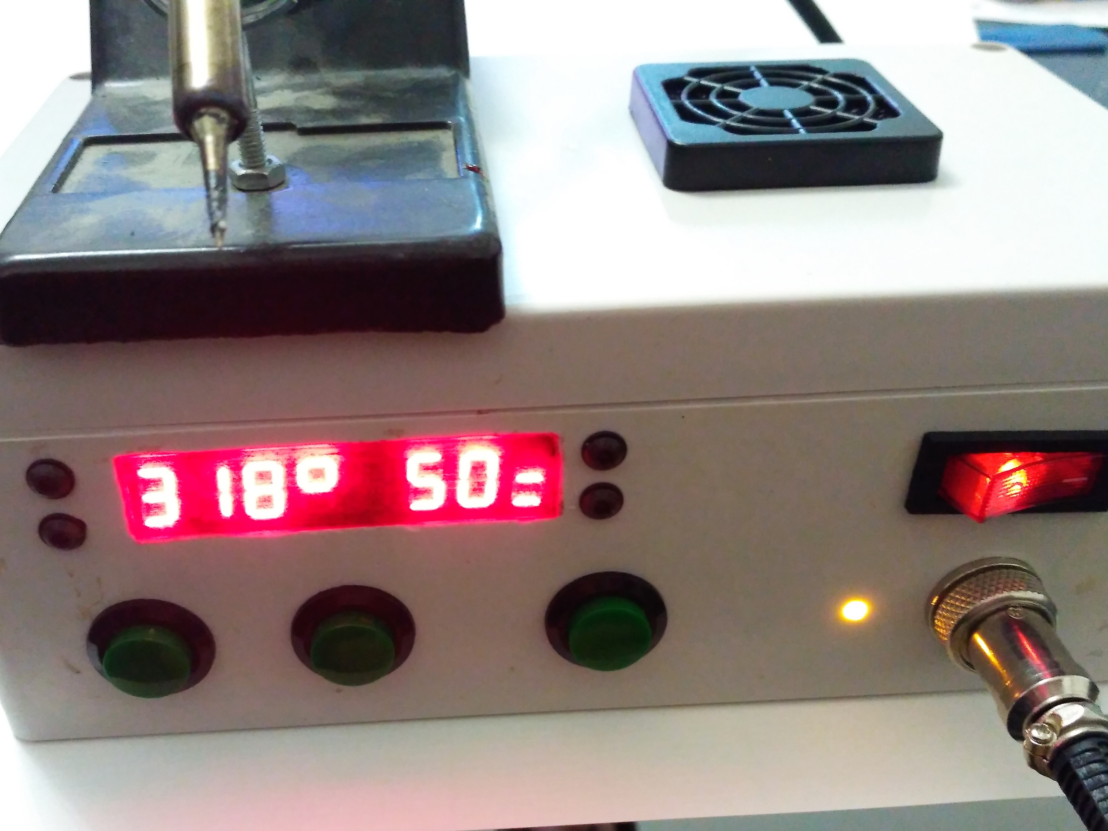
On the right half of LED display you can see defined temperature and in the left side real temperature of iron readied by thermocouple K-type.

CLASS 2. Power control mode. In this mode, you can set power level from 0% to 100%. Controls is same in Class 1 - button 1 (up) and button 2 (down) long and short press. Right half display - desired power level and left side - iron temperature.
Change working mode by short press on Button 3. Long press on button 3 to standby mode
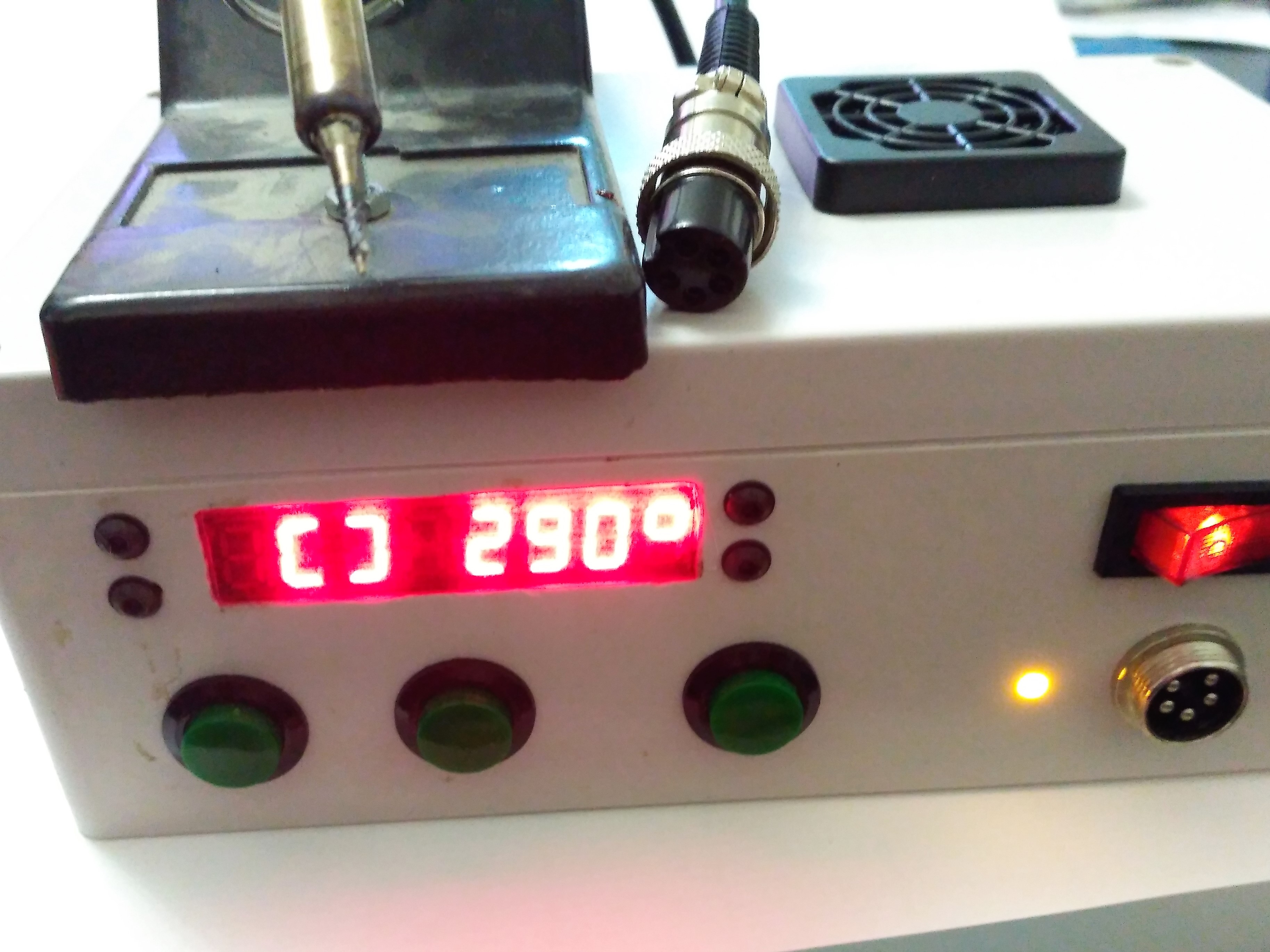
If iron handle is unplugged or there is other problem and it is impossible to read data from thermocouple, special symbol shown instead iron temperature both in standby and in working mode

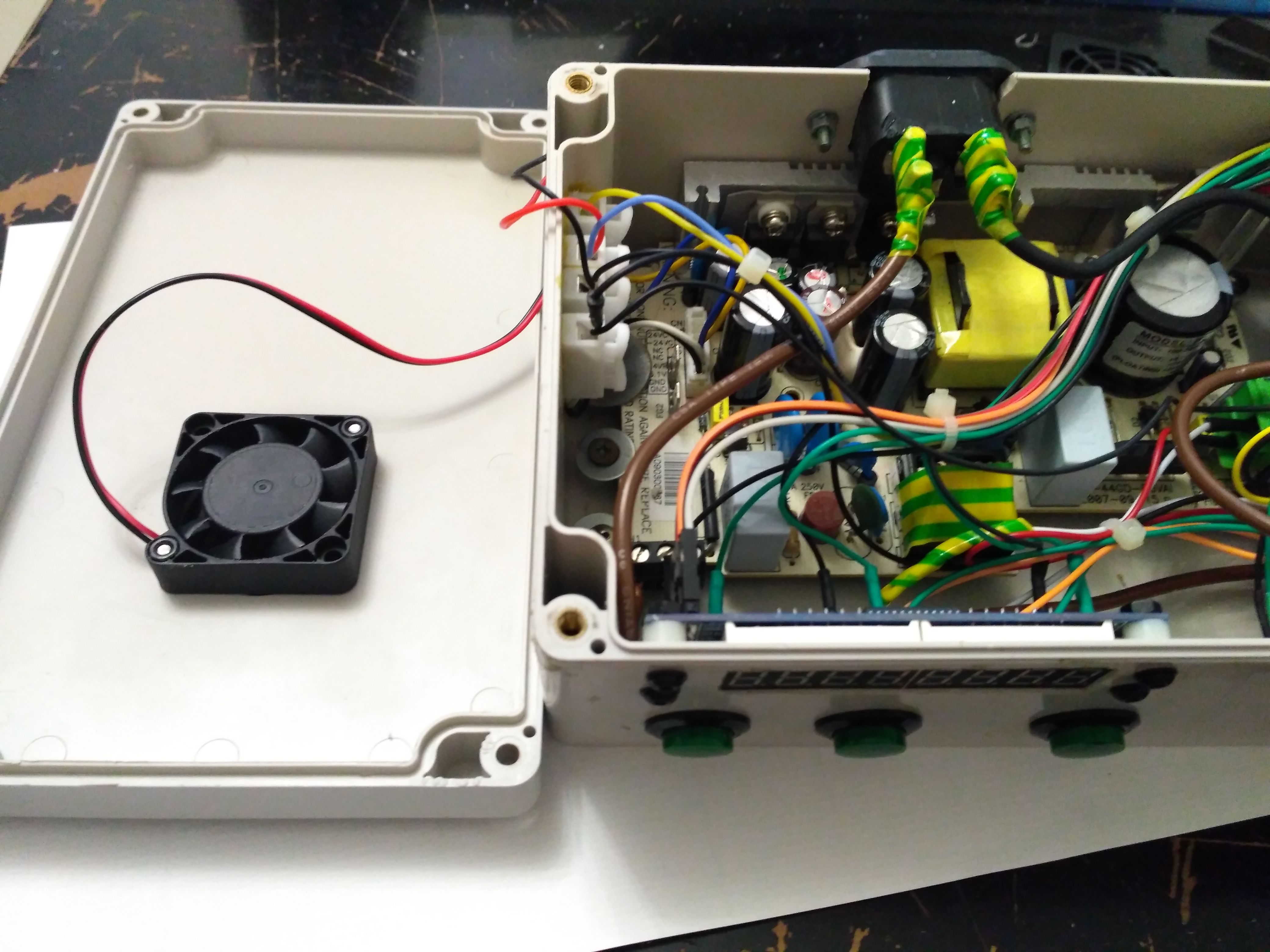
Modules
Station have a module structure and almost not discreet components. Only one descrete component is resistor for LED indicator of heating.
1. Power supply. I use power supply from old fax machine that have +5 and +24 volt out that i need.
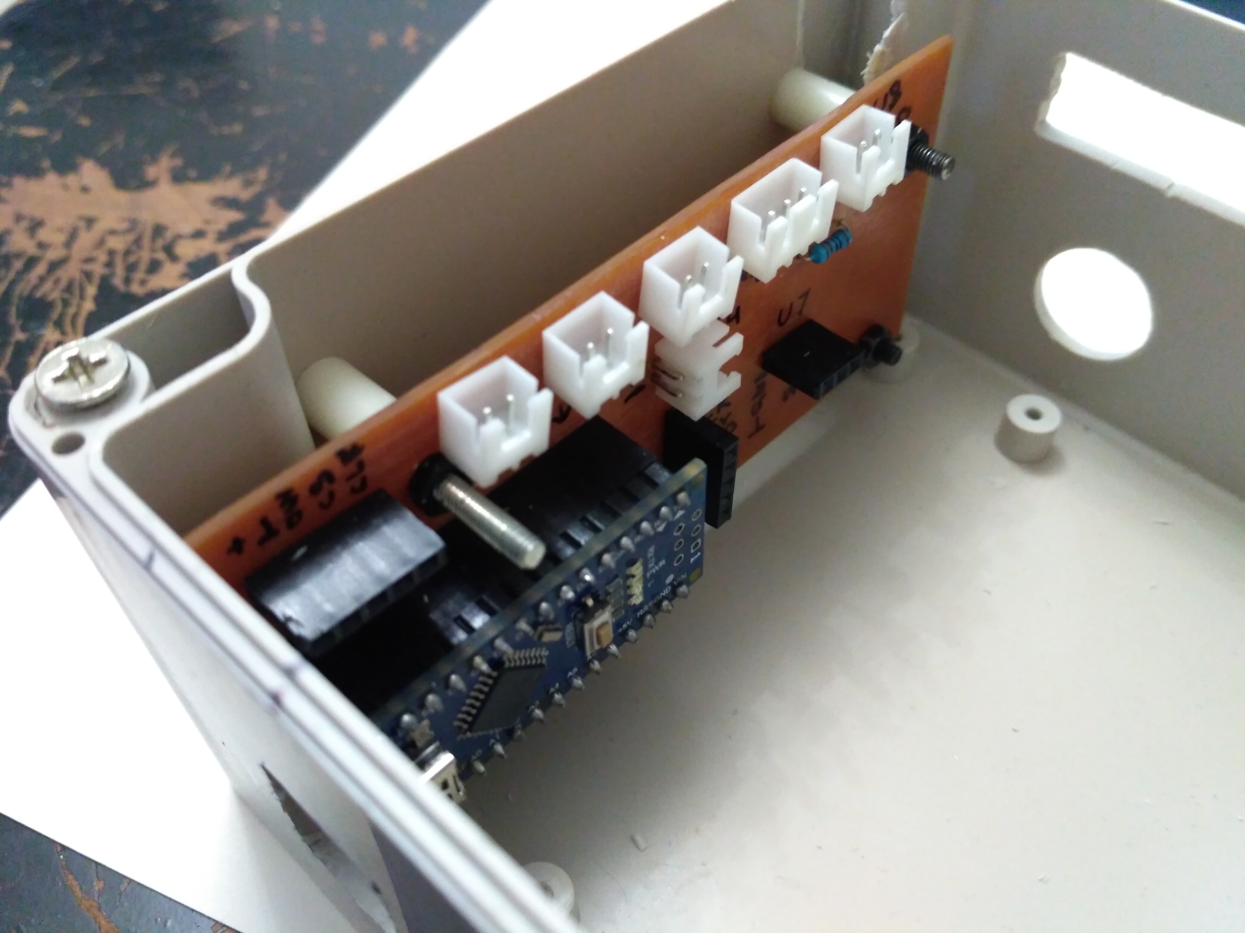
2. Modules.
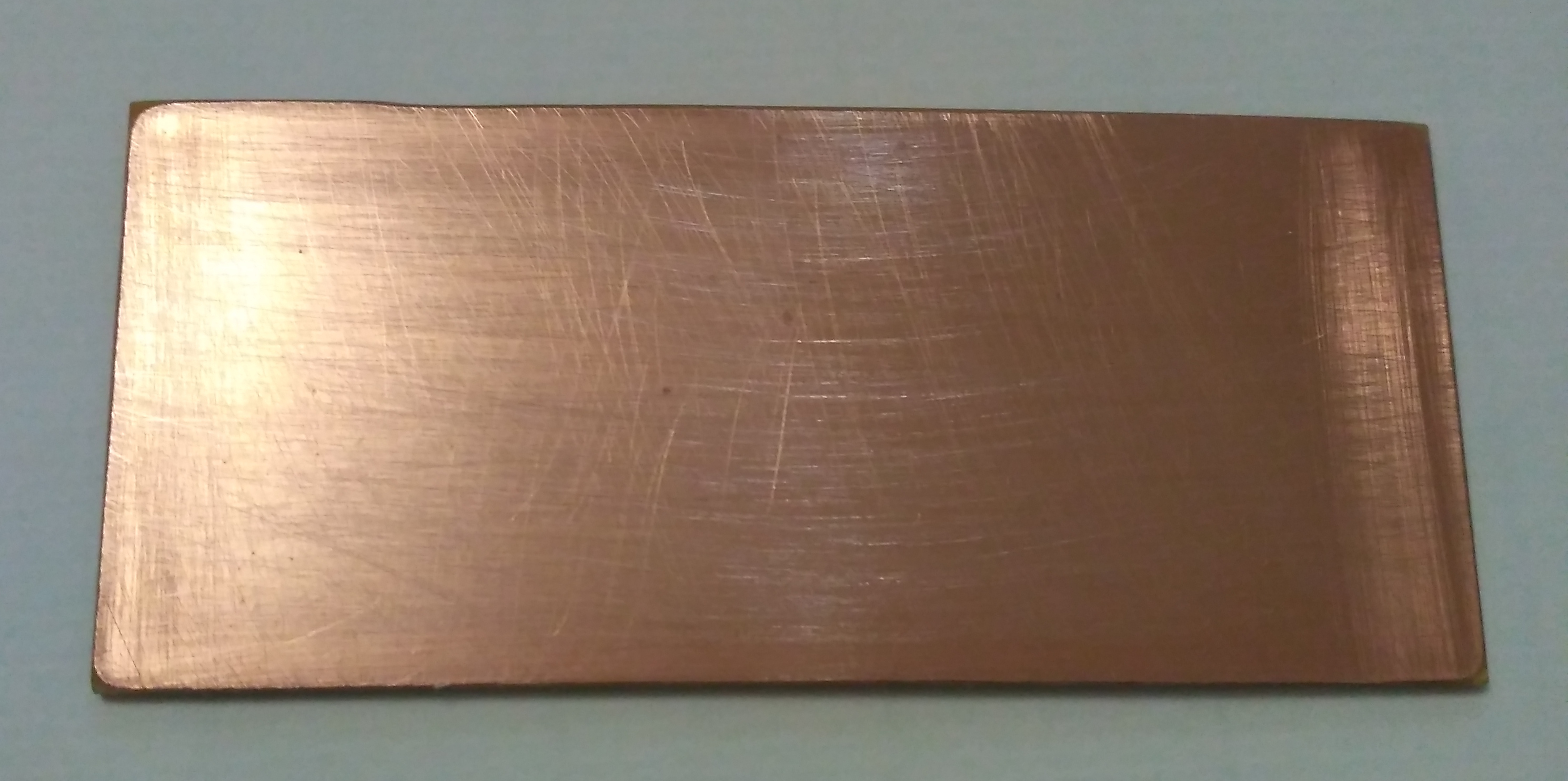
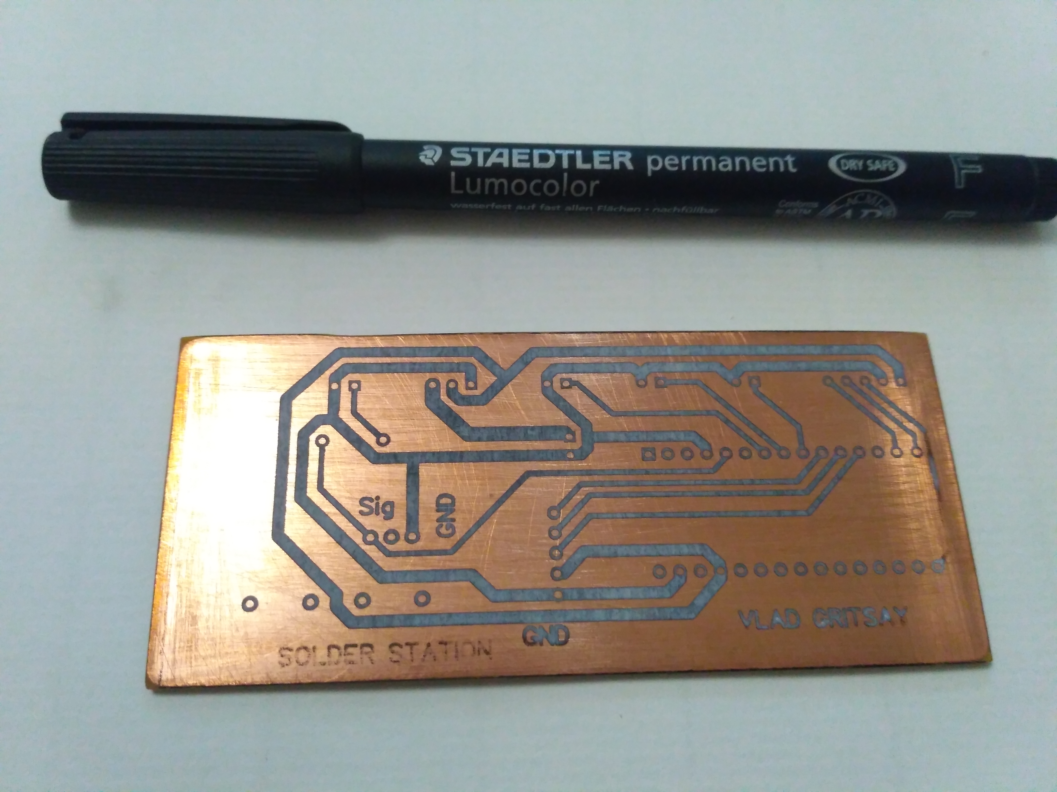
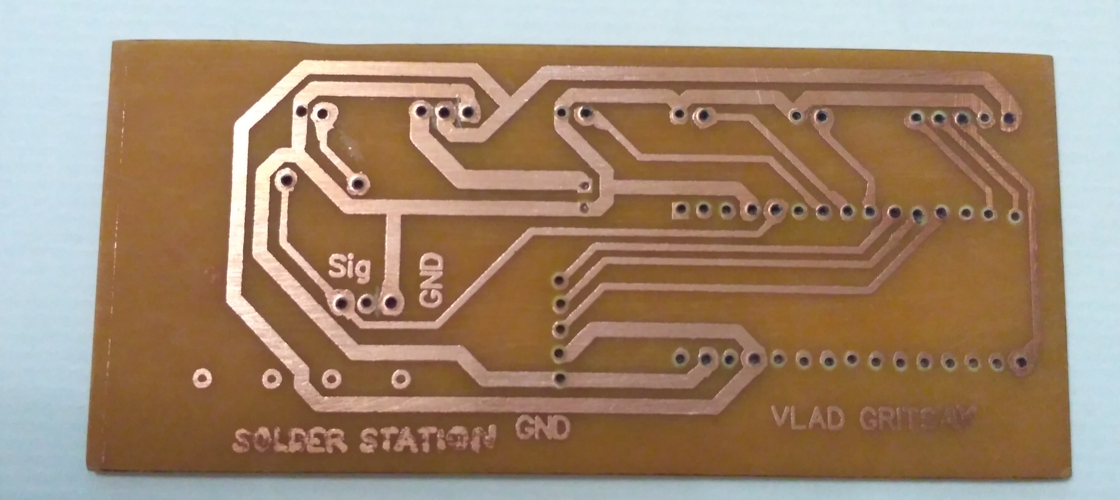
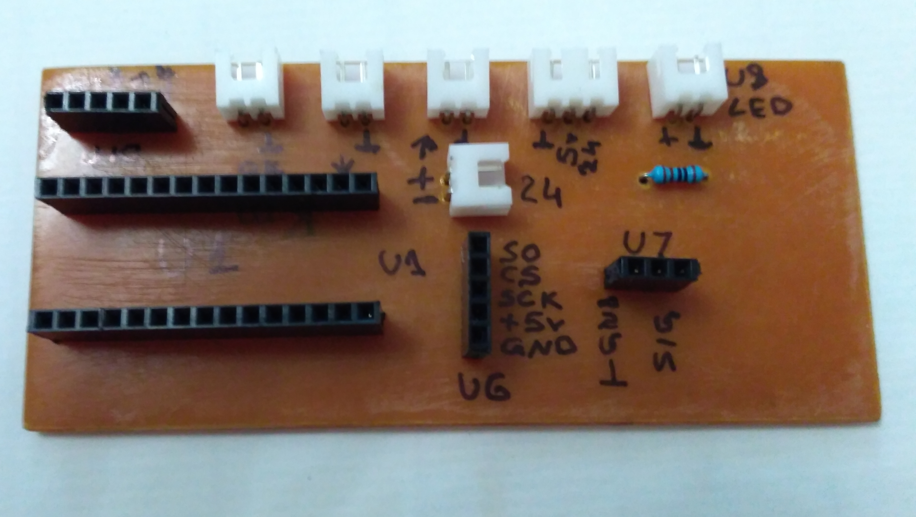
- Arduino NANO. It placed on my own PCB with all needed connectors an headers that i produce by laser transfer technology. However it is possible to use breadboard for this target.
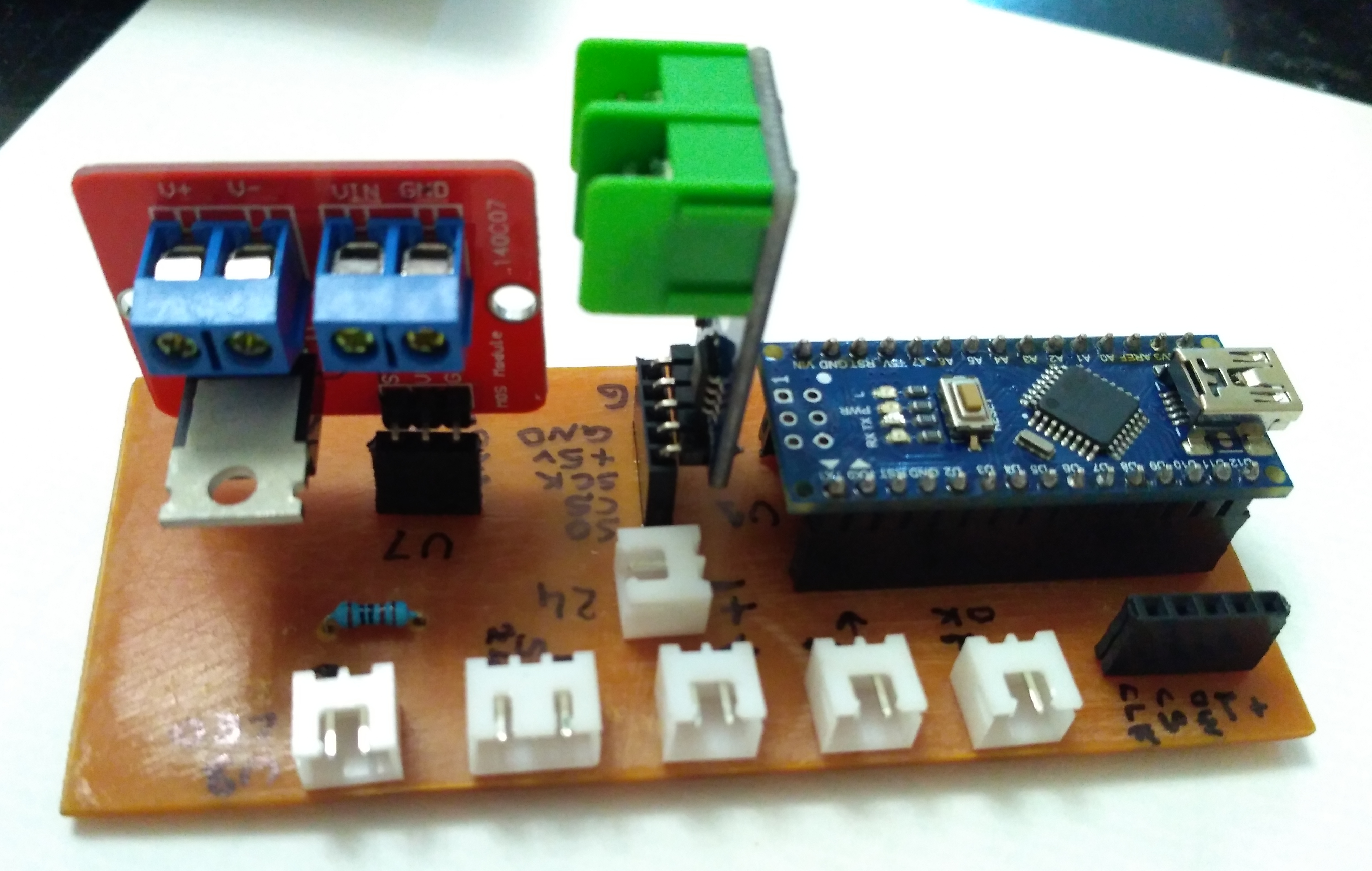
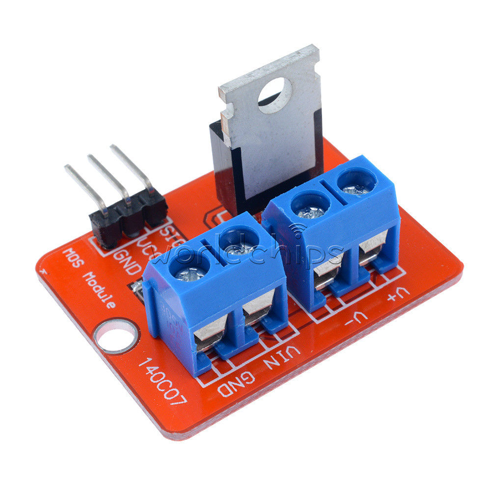
- IRF520 mosfet module for heater control
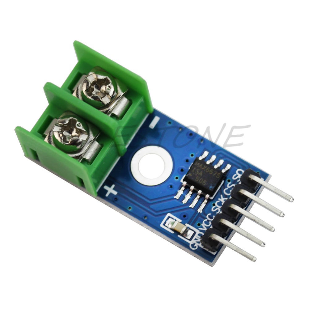
- MAX6675 thermocouple K-type driver
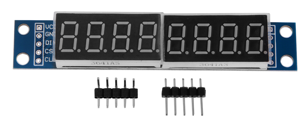
- MAX7219 8 digit module
That's all that you need!!!!!
In addition, you need a simple passive element such buttons, connectors, wires and plugs.
EXPANDED TECHNICAL DETAILS
A cheap $10 soldering iron just dumps 110V power into a metal rod until it glows orange and burns your PCB. The DIY Arduino Soldering Station replicates a $300 industrial Hakko unit. By harnessing extreme mathematical PID (Proportional-Integral-Derivative) control, it actively reads the microscopic temperature of the tip a thousand times a second, firing heavy Mosfets to maintain absolute thermodynamic perfection.
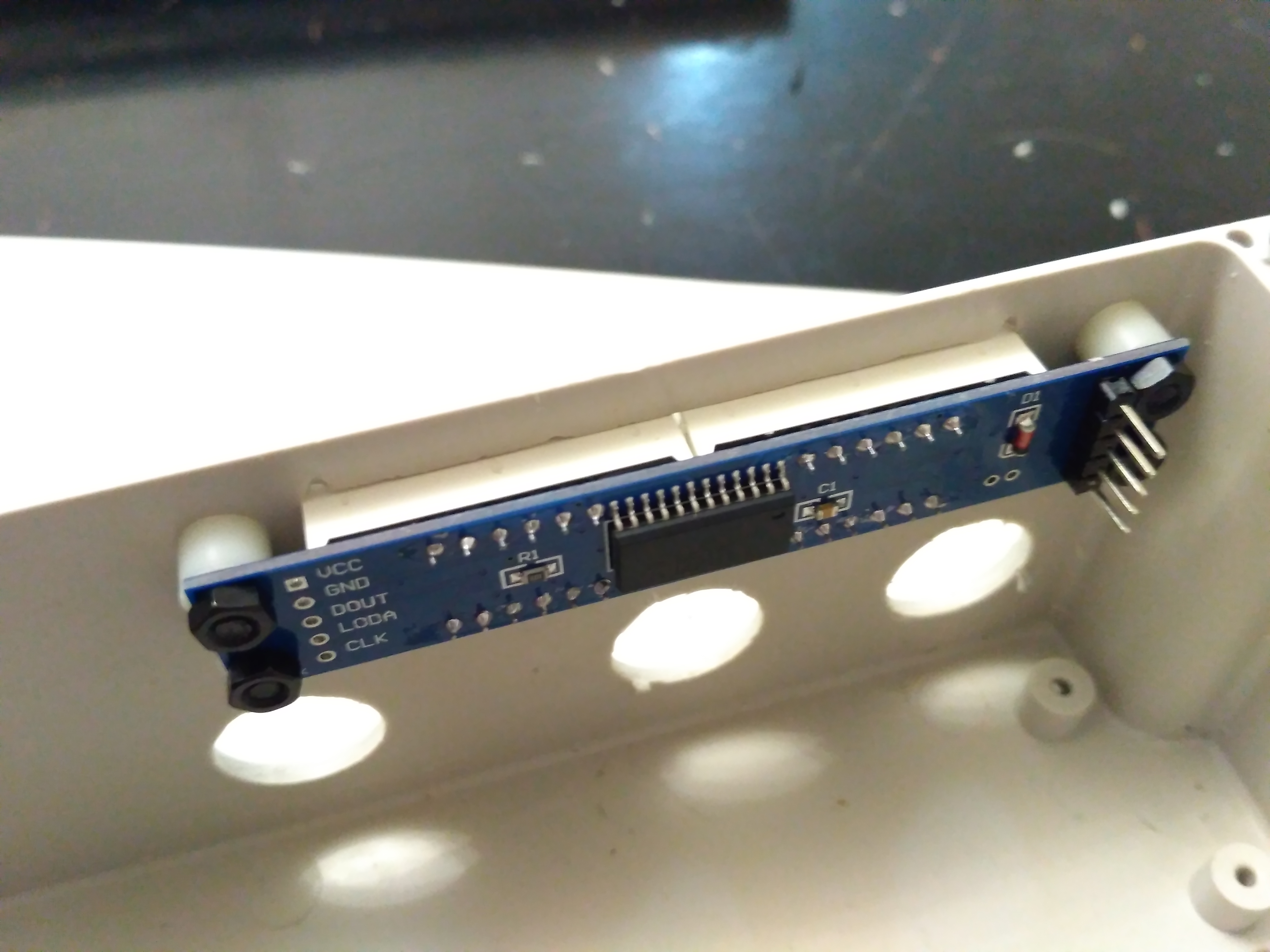
Amplifying the Thermocouple (MAX6675 Module)
A premium soldering tip contains two items: a heavy heater coil, and a microscopic Thermocouple.
- The thermocouple generates an incredibly tiny voltage as it gets hot—usually in the raw millivolts domain (e.g.,
0.005 Voltsat 300 Celsius). - The Arduino's analog pin cannot read
0.005V; it is too low-resolution. - This project uses the MAX6675 module (shown in the image above) to solve this problem. This integrated chip amplifies and digitizes the tiny thermocouple signal, providing a clean, high-resolution digital temperature reading to the Arduino via SPI communication.
The Power Control (IRF520 MOSFET)
If you just turn the power ON when it is too cold, and OFF when it gets too hot, the temperature will violently bounce, destroying delicate silicon chips.
- This project uses a simple but effective control scheme, but the principle is similar to PID.
- The system reads the temperature from the MAX6675 and dynamically commands the IRF520 MOSFET module (shown in the image above).
- It switches the 24V current to the heater element to bring the tip to the target temperature and maintain it there, preventing dangerous overshoot.
Industrial Fabrication Components
- Arduino Nano (The standard for DIY workstations).
- MAX6675 Thermocouple Amplifier Module (To read and digitize the hidden thermocouple signals).
- IRF520 Heavy-Duty MOSFET Module (Required to switch the 24V heater current from the ATmega logic level).
- A 24V / 4A Switching Power Supply (The heavy lifting engine).
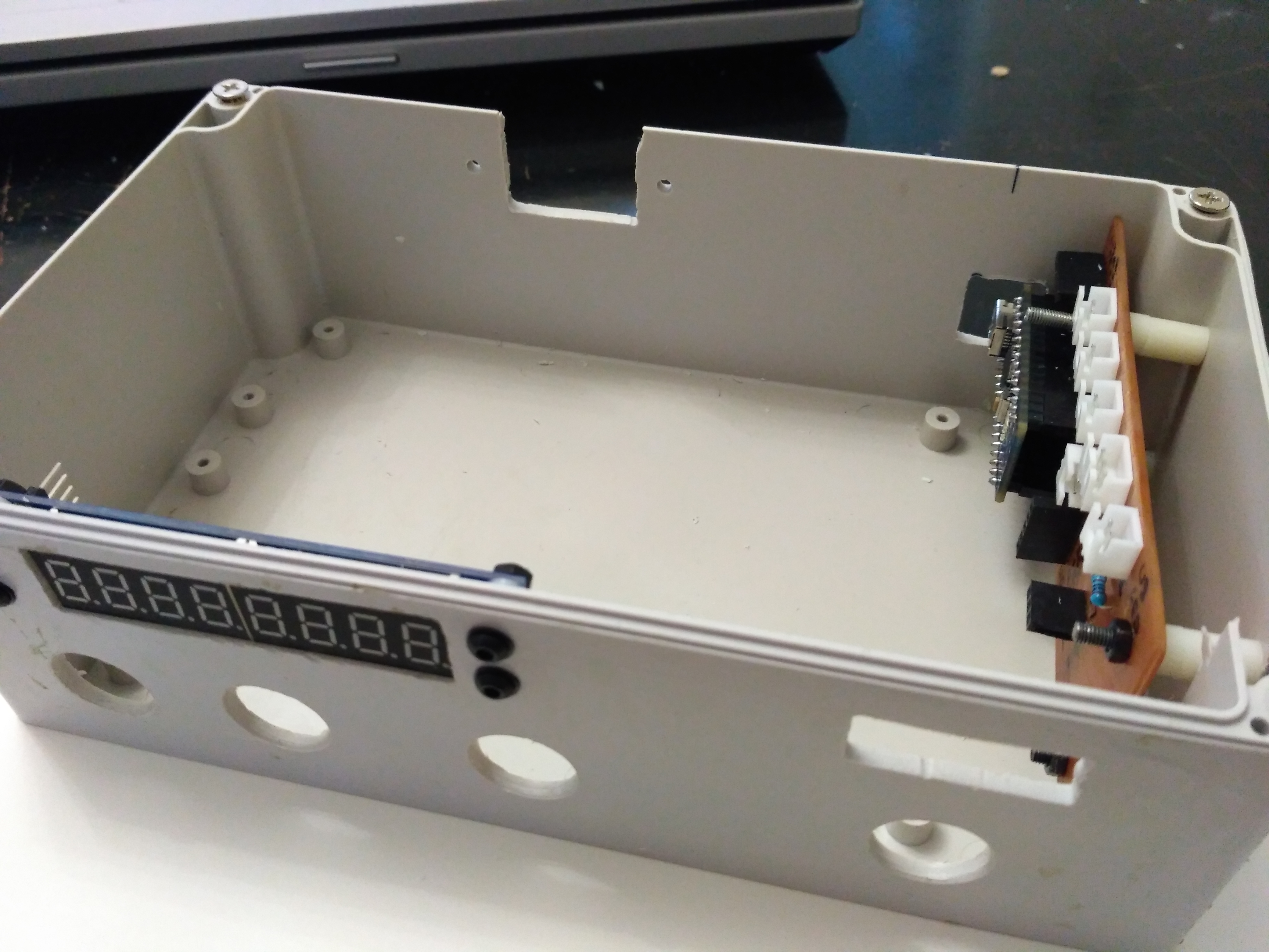
Case
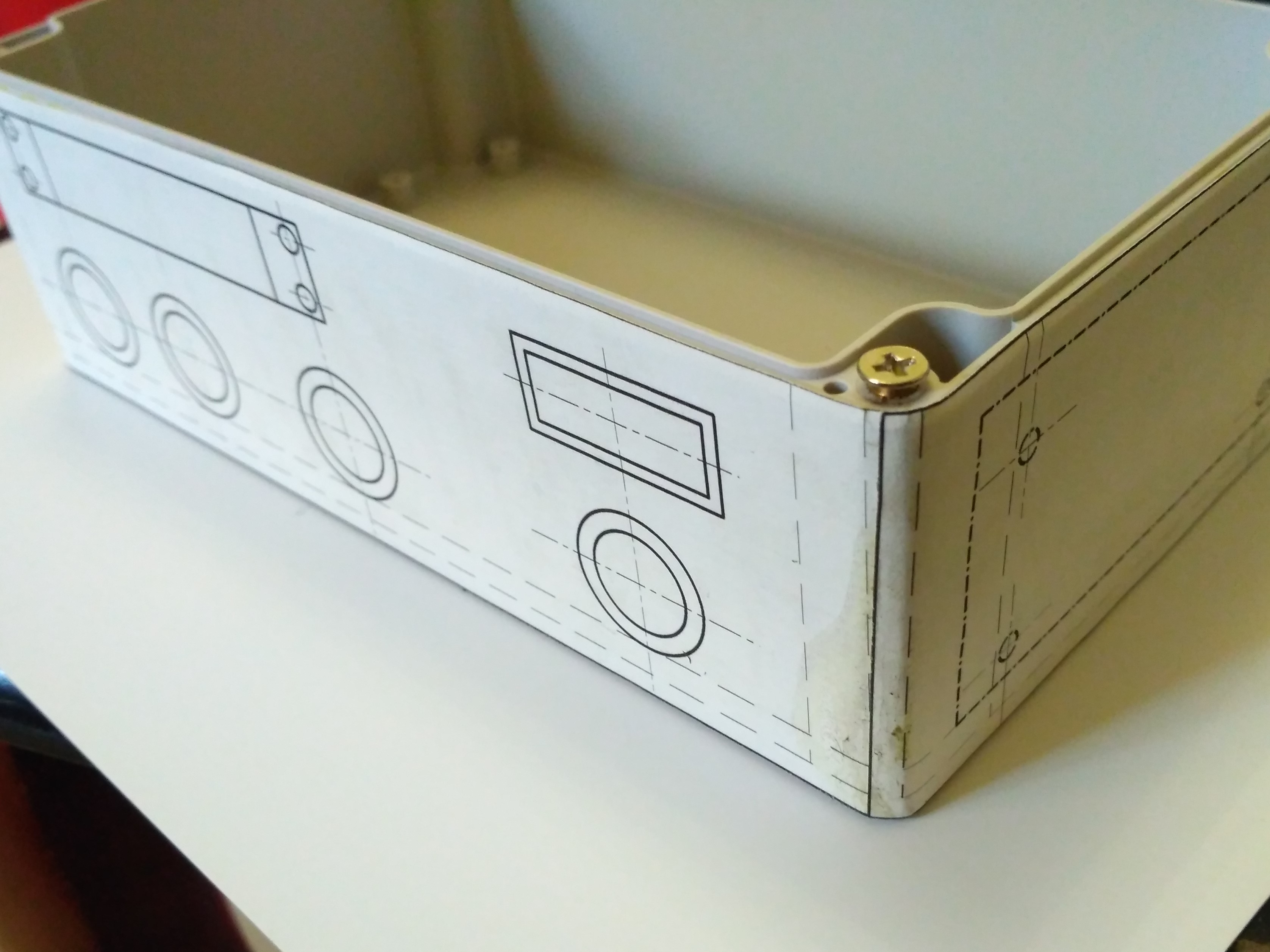
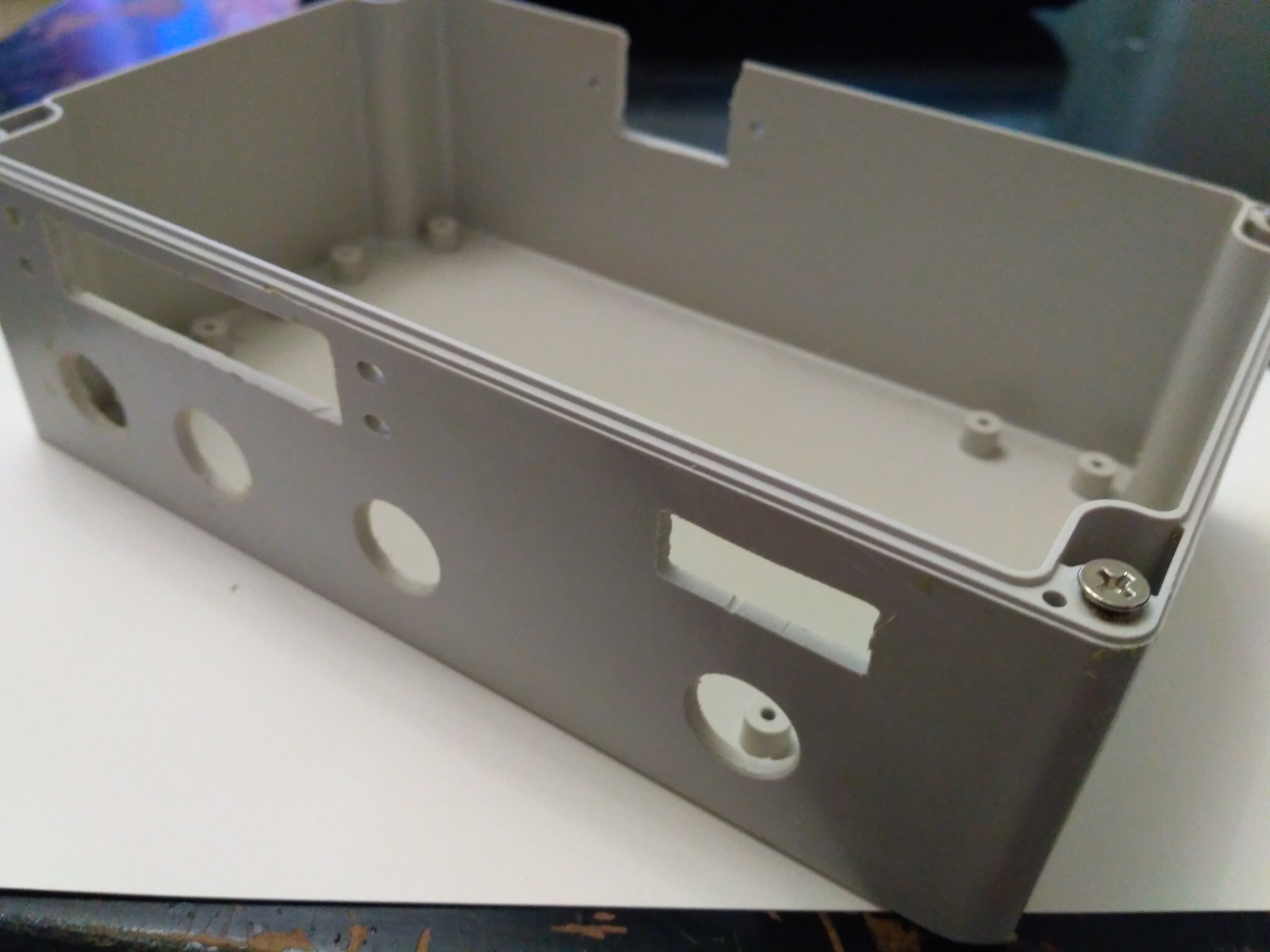
Assembling
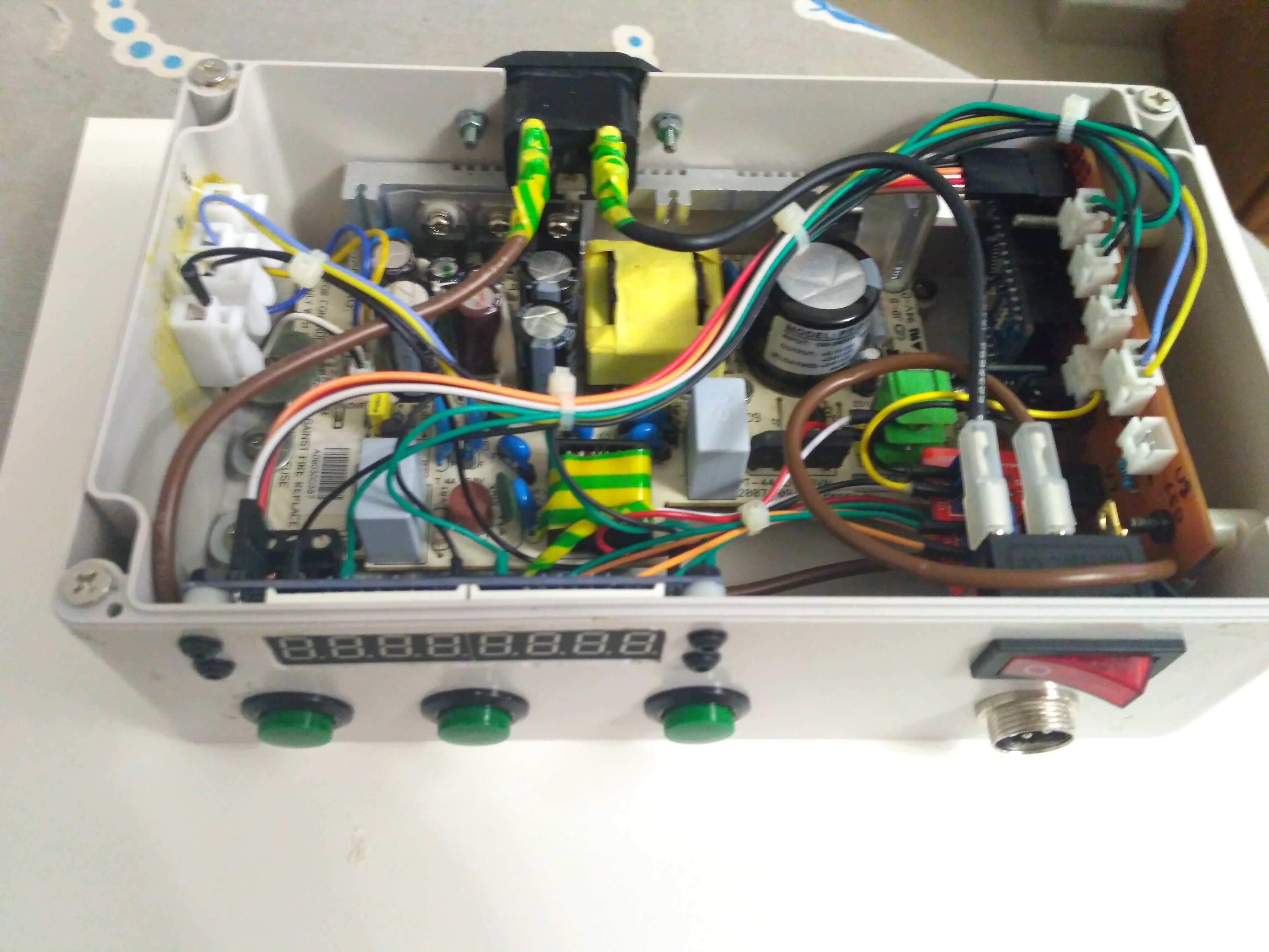
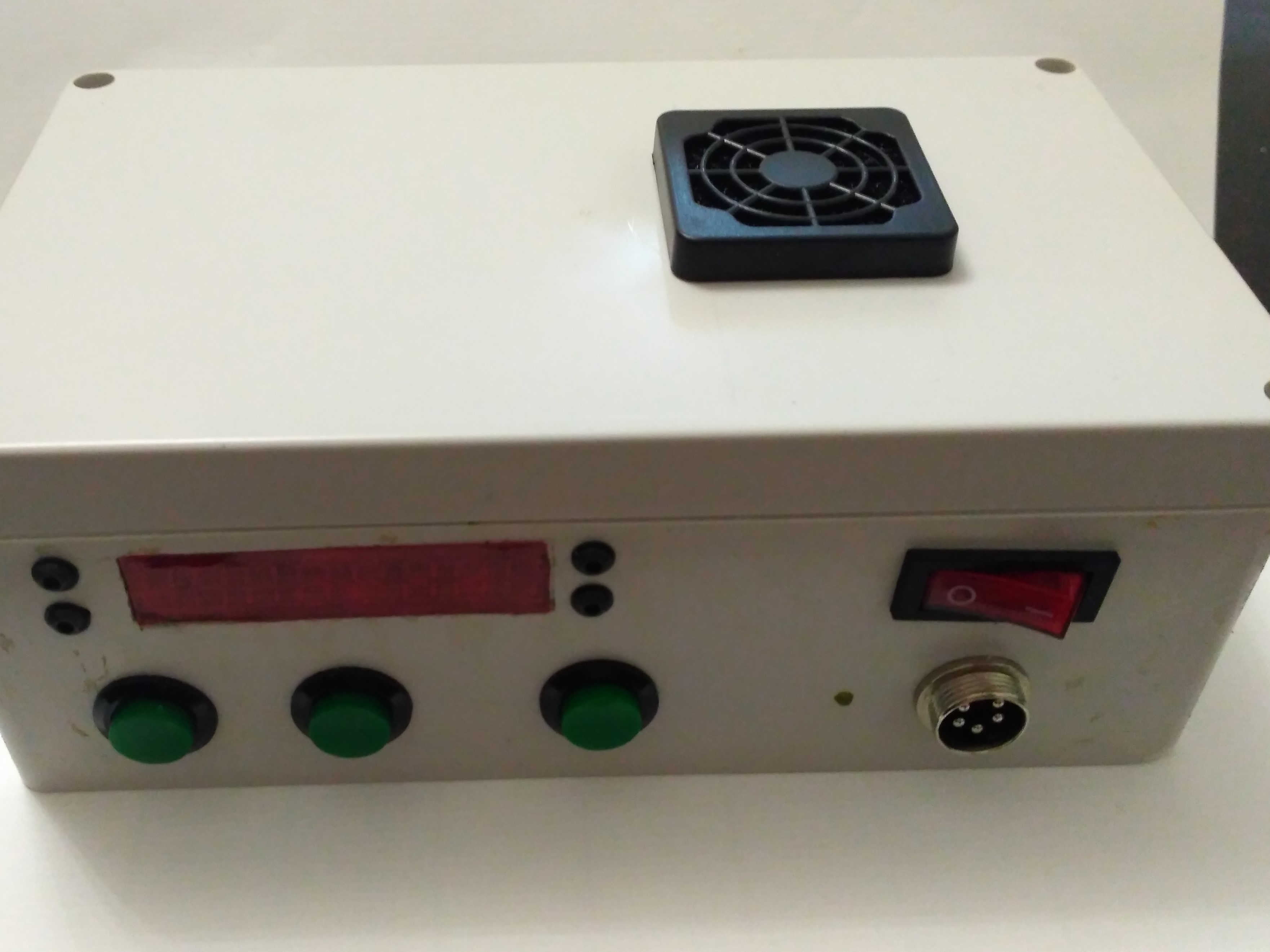
Result
Sketch
Sketch is very simple, not use PID, classes, objects and hard to understanding things. All include libraries you can find over internet and download. Only one special library that I use is "sav_button" library that you can download and find here. It used to control button state. I found it in internet, it written by Alexey Shikharbeev. Thanks.