Hello.
In this Project, you will create a button press LED. When The button is pressed, the LED will turn on. In the Tips and Tricks after the trouble shooting page, you may add a off button to turn the LED off. Don't worry, the full code will be provided. Finally, don't forget to check out my website and YouTube channel!
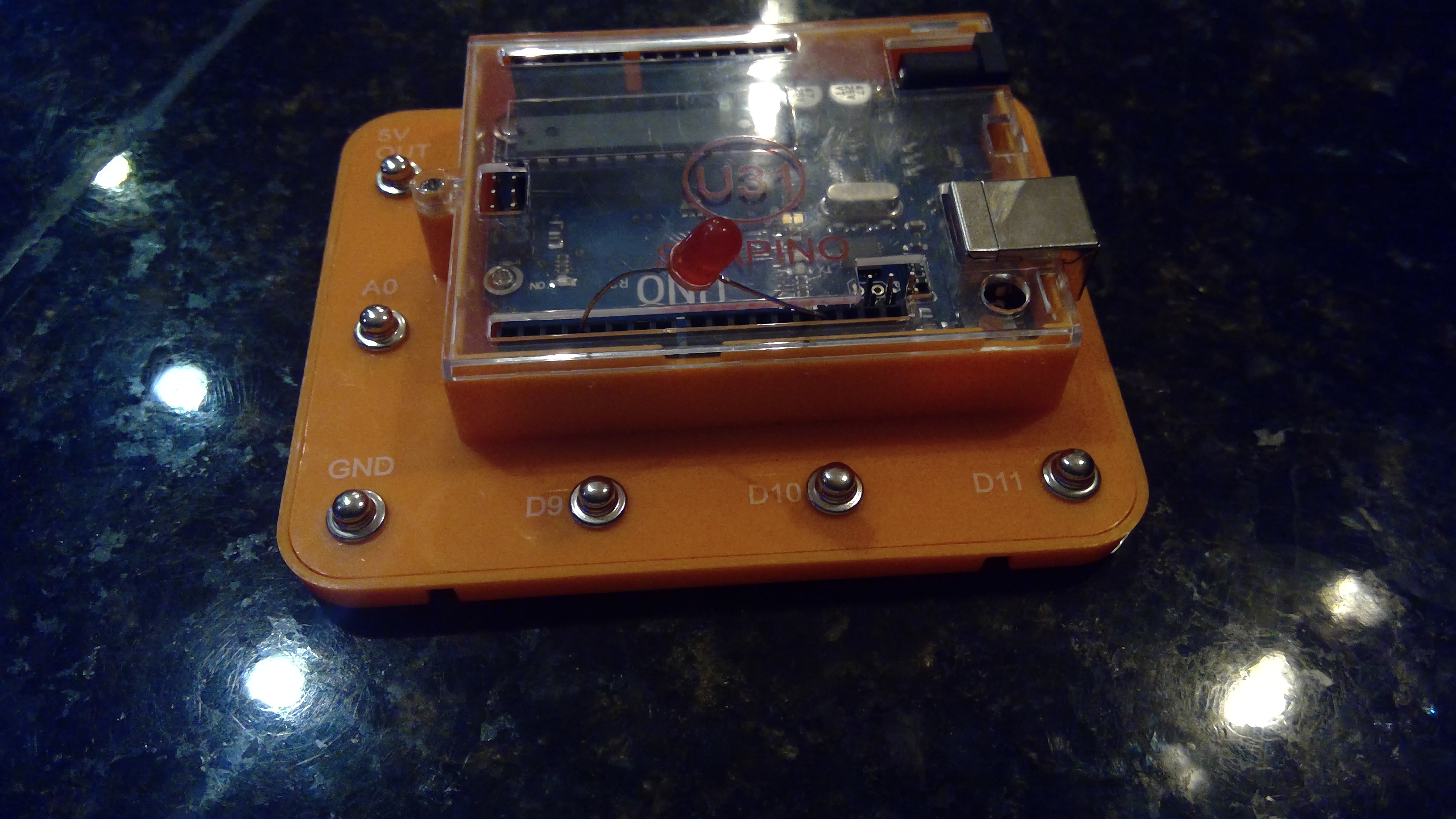
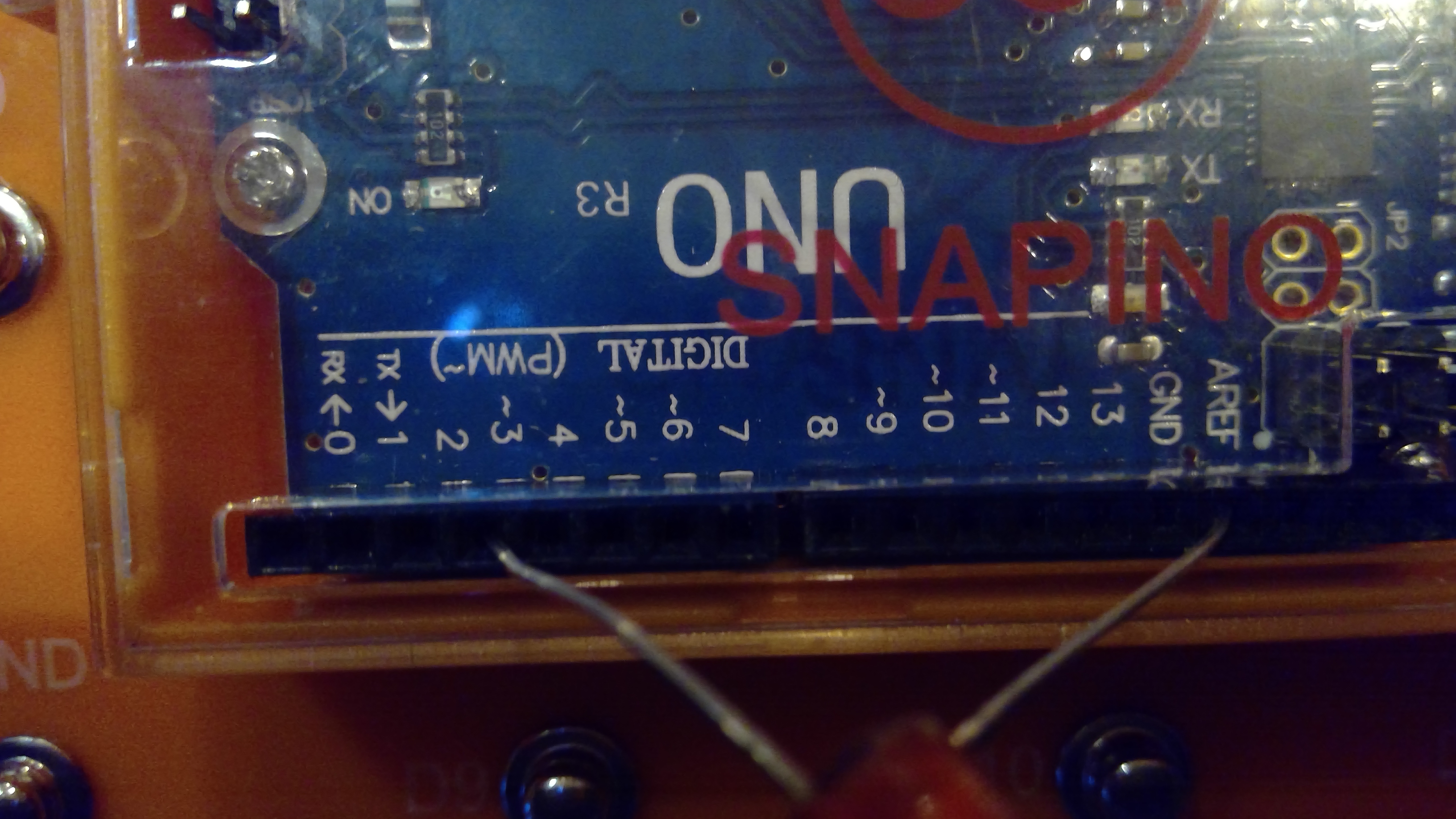
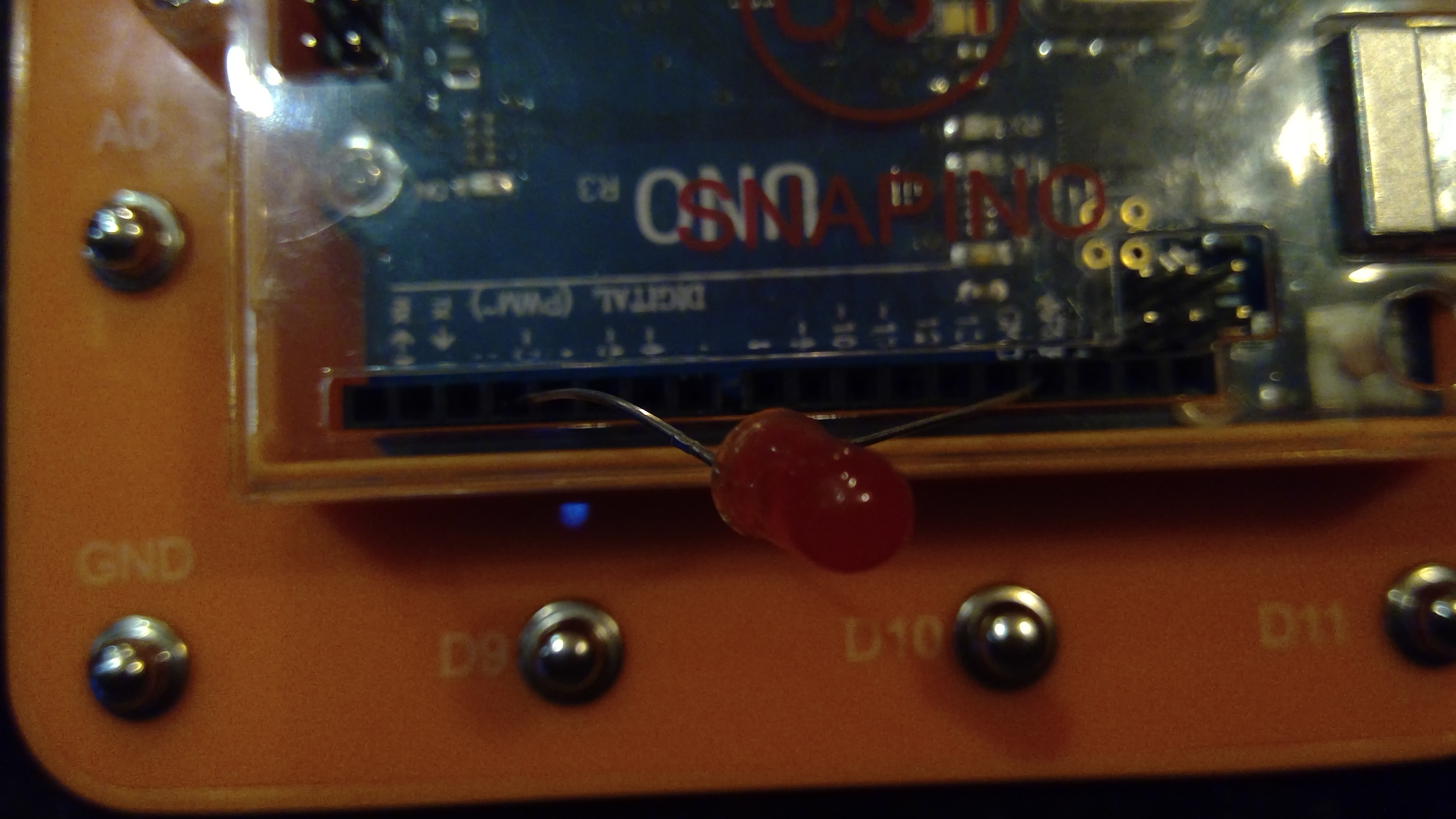
Attaching The LED To The Uno
Lets start with adding the LED. The LED will be attached to pin3. Don't forget that the LED is on the digital side, not the Analog. An image is provided below.
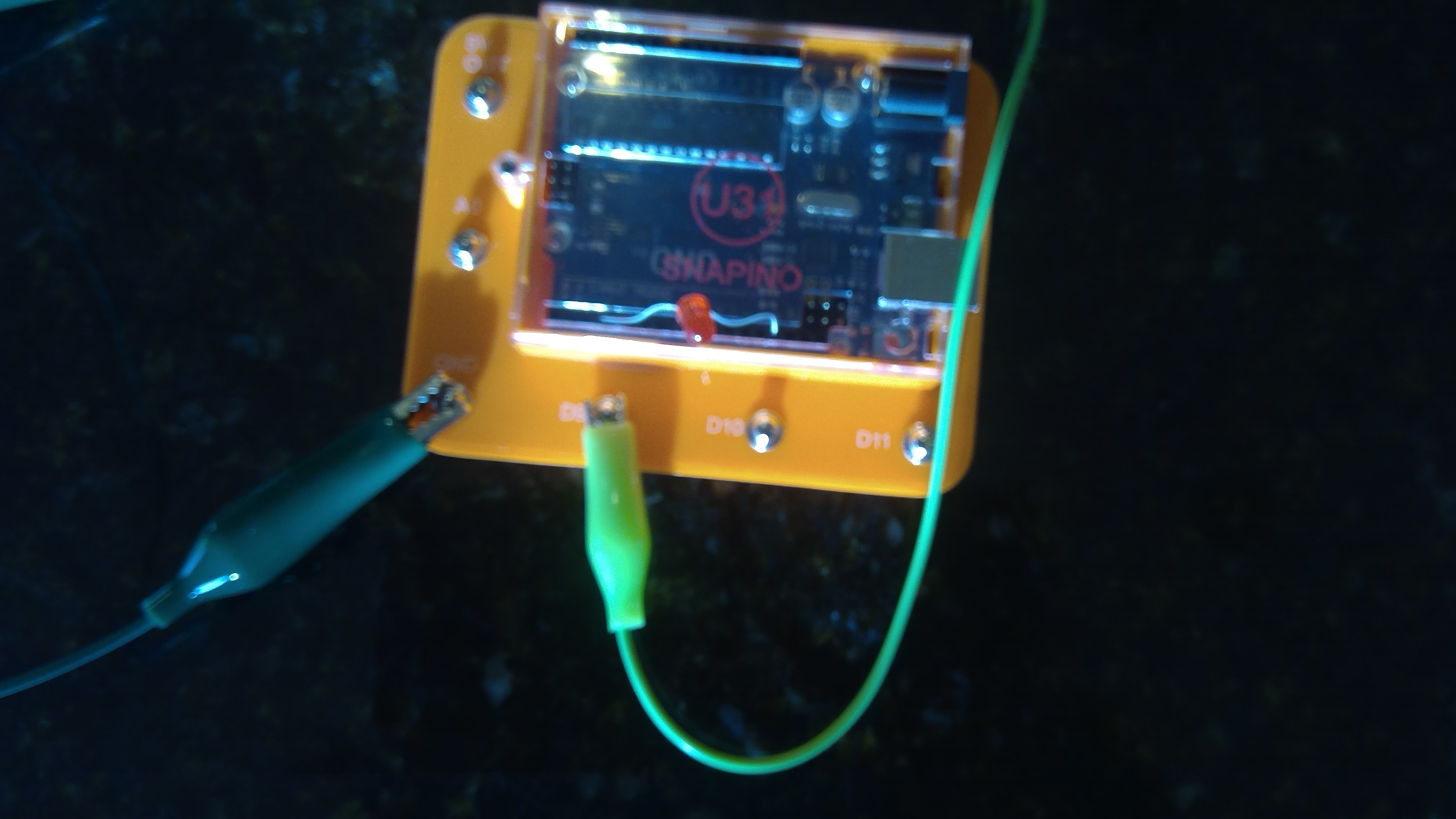
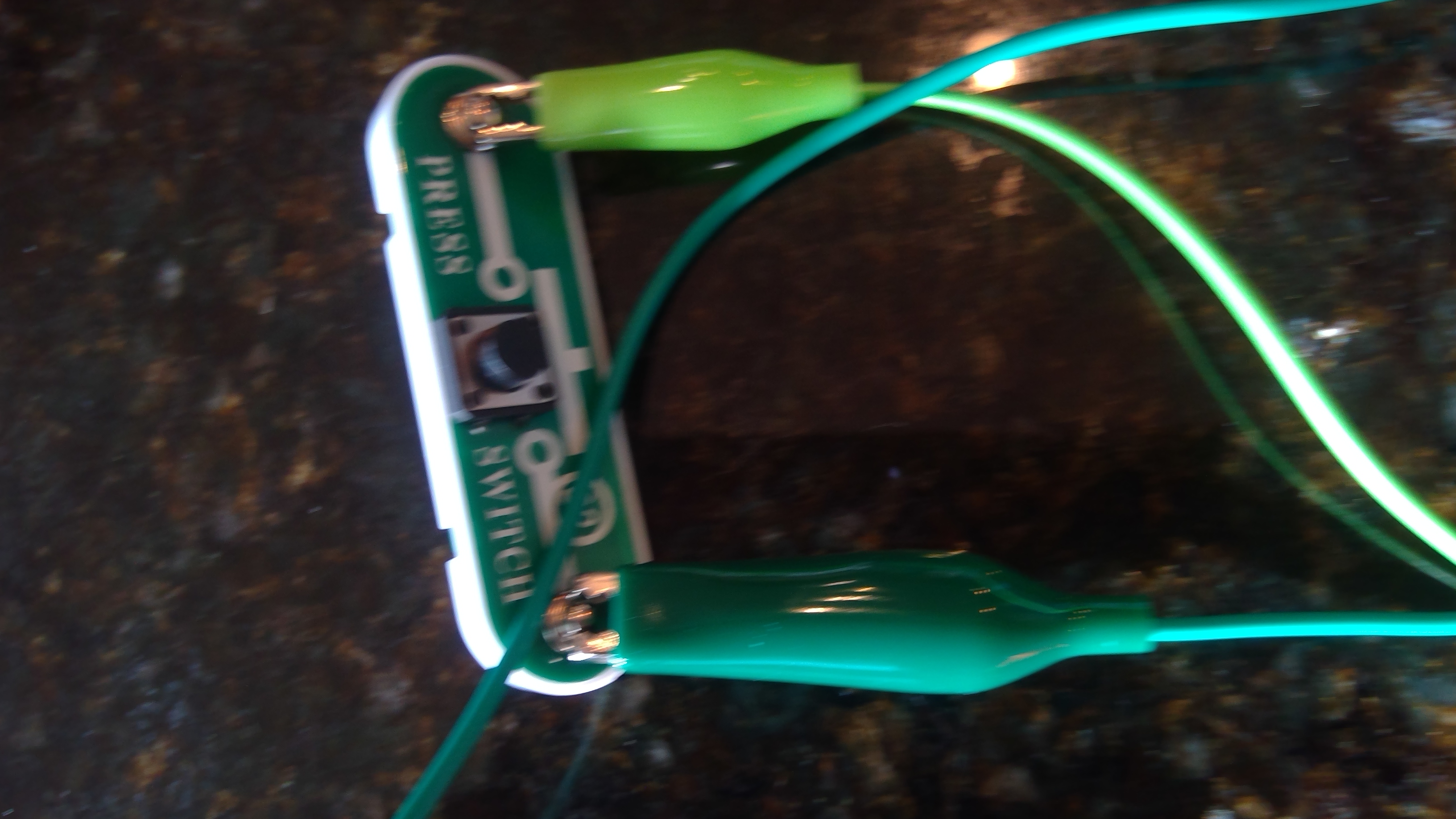
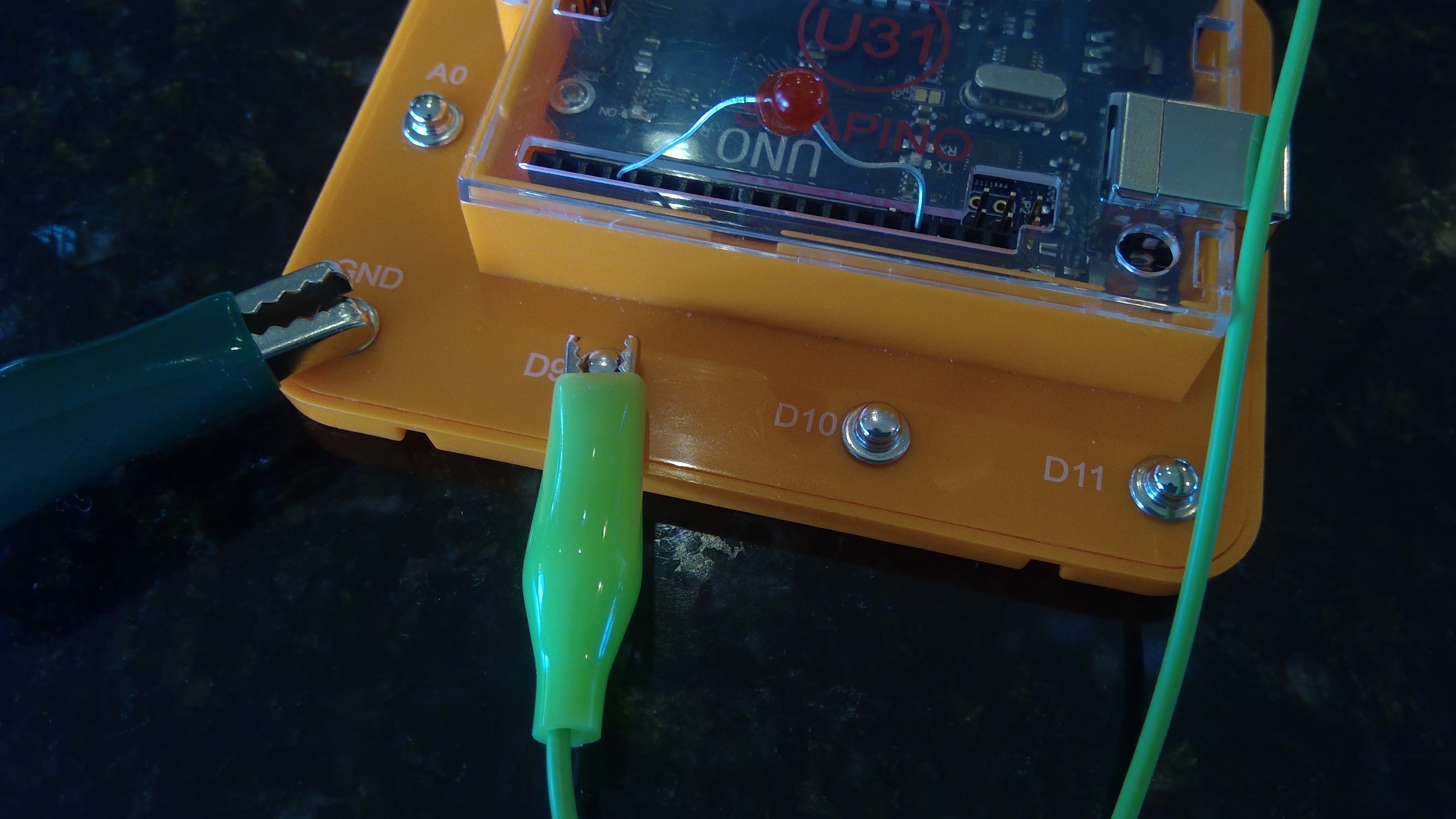
Adding The Button To The Uno
Now that we have the LED connected to the Snapino, we may add the button to activate the LED. Add the button to D9 and make sure that the LED and button are connected to ground(GND). You may use a different button, but ensure it is SPST(Single Pole Single Throw).

Writing the CODE
Finally lets write the code. Don't you worry! You ain't writing it all with the indents and curly brackets and brackets and quotation marks! The code is provided below. Make sure you copy and paste it in your IDE. If you do not have the Arduino IDE, see arduino.cc
Enter this code into your IDE:
void setup() {
//button1
pinMode(9, INPUT);
//led1
pinMode(3, OUTPUT);
}
void loop() {
if(digitalRead(9)==LOW){
digitalWrite(3, HIGH);
}
}
____________________________________-______-_______--
Don't forget that DO NOT TYPE void setup() { and void loop() {.
____________________________________-______-_______--
Troubleshooting
If you code does not work, try the following:
Make sure Your Button is connected to ground
Make sure your LED is connected to ground
Make sure you have not used hot glue on your button and it works
Make sure LED is not burnt out or does not work
Try running the Snapino test program to ensure the Snapino UNO is working properly
Tips and Tricks
If you would like to go farther, try one of these tricks:
-- You could add a off button to turn the LED off using this code:
void setup() {
//button1
pinMode(7, INPUT);
//button2
pinMode(8, INPUT);
//led1
pinMode(3, OUTPUT);
}
void loop() {
if(digitalRead(7)==LOW){
digitalWrite(3, HIGH);
}
if(digitalRead(8)==LOW){
digitalWrite(3, LOW);
}
}
The LED would be connected to pin 3 The button to turn it on will be on pin 7 and your off button will be on pin 8.
-- Change the code so the led starts on and you press the button to turn it off using this code:
void setup() {
//button1
pinMode(10, INPUT);
//led1
pinMode(3, OUTPUT);
}
void loop() {
if(digitalRead(10)==LOW){
digitalWrite(3, LOW);
}
}
_______________-___-_-_-__-_-_____-_____-______-_____-_
Successful


That is The end. You just made a code or program to have it where when you press a button, the LED turns on! Great job! Have a good day with your new code! Don't forget to save it on your computer so you can use it again.
Thank you.
EXPANDED TECHNICAL DETAILS
Basic Interaction Logic
A fundamental "Hello World" project for hardware interfacing, focusing on the core relationship between an input trigger and a physical output.
- Digital I/O Mapping: Shows how to configure one Arduino pin as an
INPUT(the button) and another as anOUTPUT(the LED). The firmware uses a simpleifcondition: when the button state isHIGH, the Arduino sends a 5V signal to the LED pin to illuminate it. - Current Protection: Highlights the necessity of a 220Ω series resistor for the LED, preventing the high-current output of the Arduino from damaging the delicate semiconductor.
Scalability
- Toggle State Flip: (Advanced version) Introduces the logic of a "Toggle" where one press turns the LED ON and the next press turns it OFF, rather than just momentary illumination.