Introduction
When I start to physically modify my BMW E46 328i Coupe to be more suitable for my occasional race track days or amateur rallying I quickly realize I need also some electronics to support my driving experience.
It starts with a simple target: To have the data logging in RaceChrono application in real-time. With my old BMW car, the refresh rate of OBDII values for RPM and throttle position is only about 2-3Hz at maximum - which is good to have an rough view, but for exporting the video with overlay gauges it is really too slow. The downshifts or RPM/throttle peaks are not even stored. It does not matter which OBD Bluetooth module I use (ELM327 China, or a $50 recommended module) I never get better performance. My goal was to feed RaceChrono with data at least each 100ms aka 10 Hz.
Preparations
I start to research how the instrument cluster/dashboard works in my car, how to hack in and what HW do I need to achieve the RaceChrono connection. Quite soon I end up with first proposal including an Arduino board with a Bluetooth and CAN modules to hook up directly to my car CANbus to read the raw values from ECU/DME and possibly also from other control units.
With such a smart Arduino device there were now opportunities to use it also for other stuff and the project evolve in a minimalistic race dashboard with:
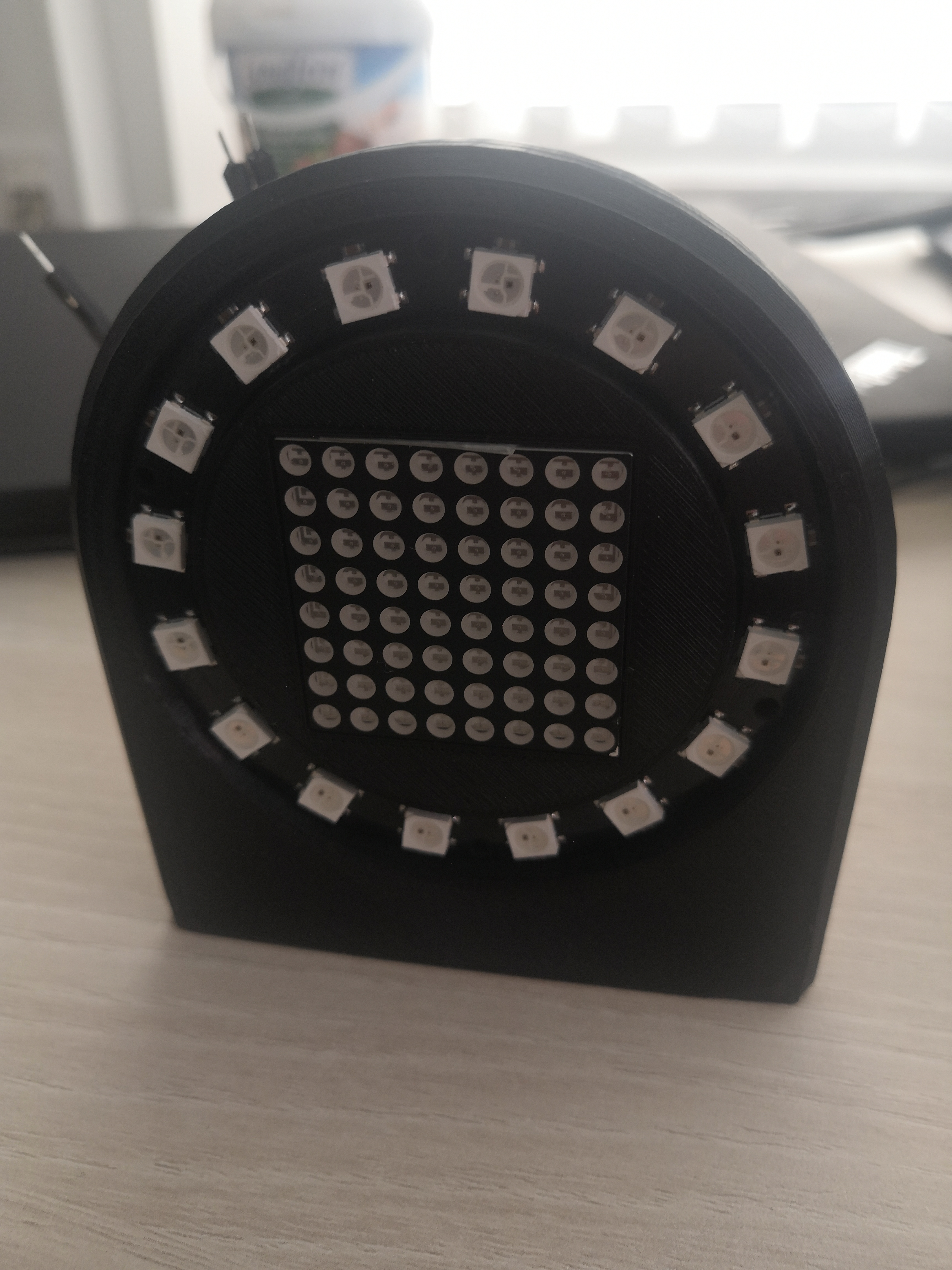
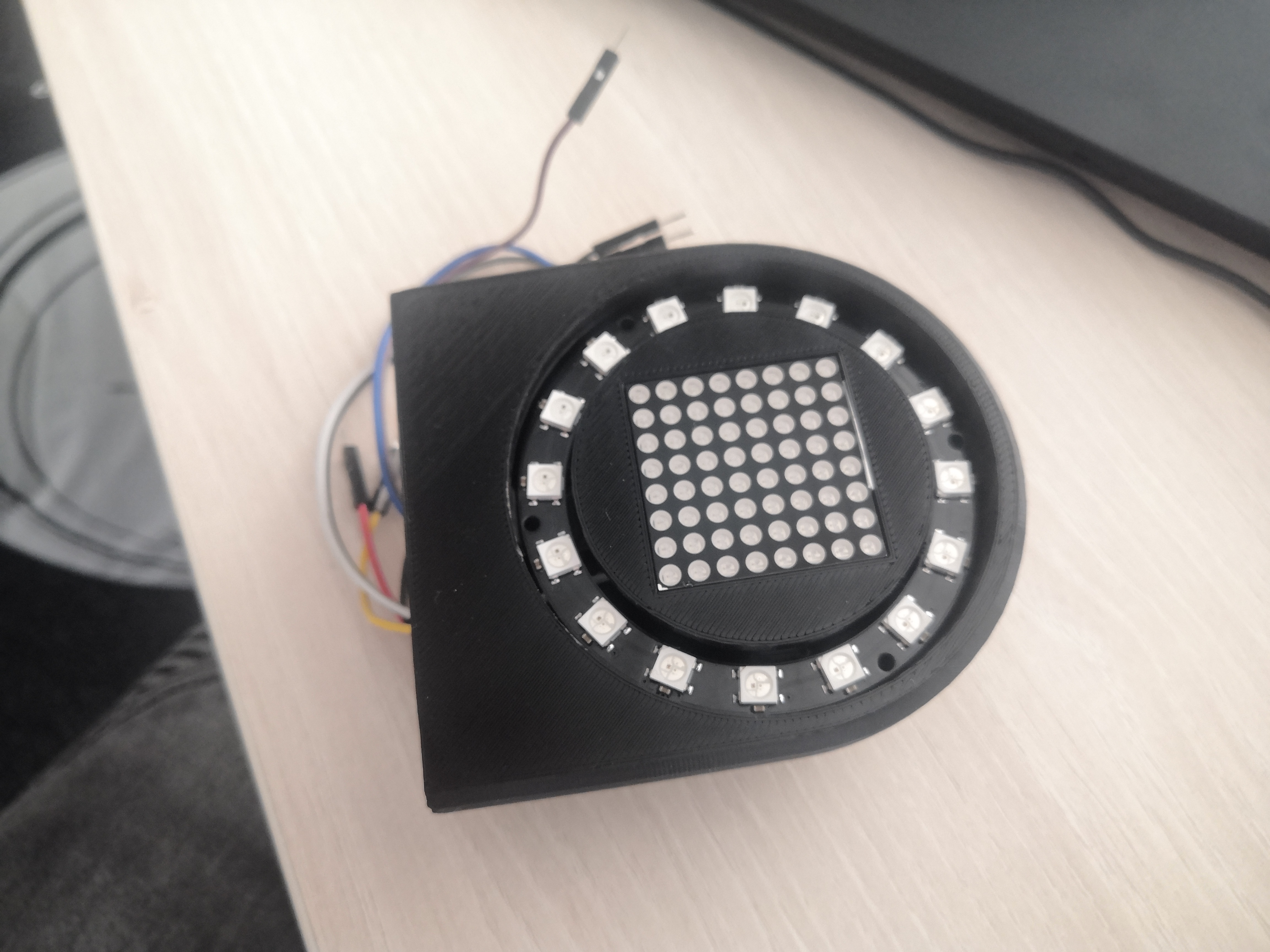
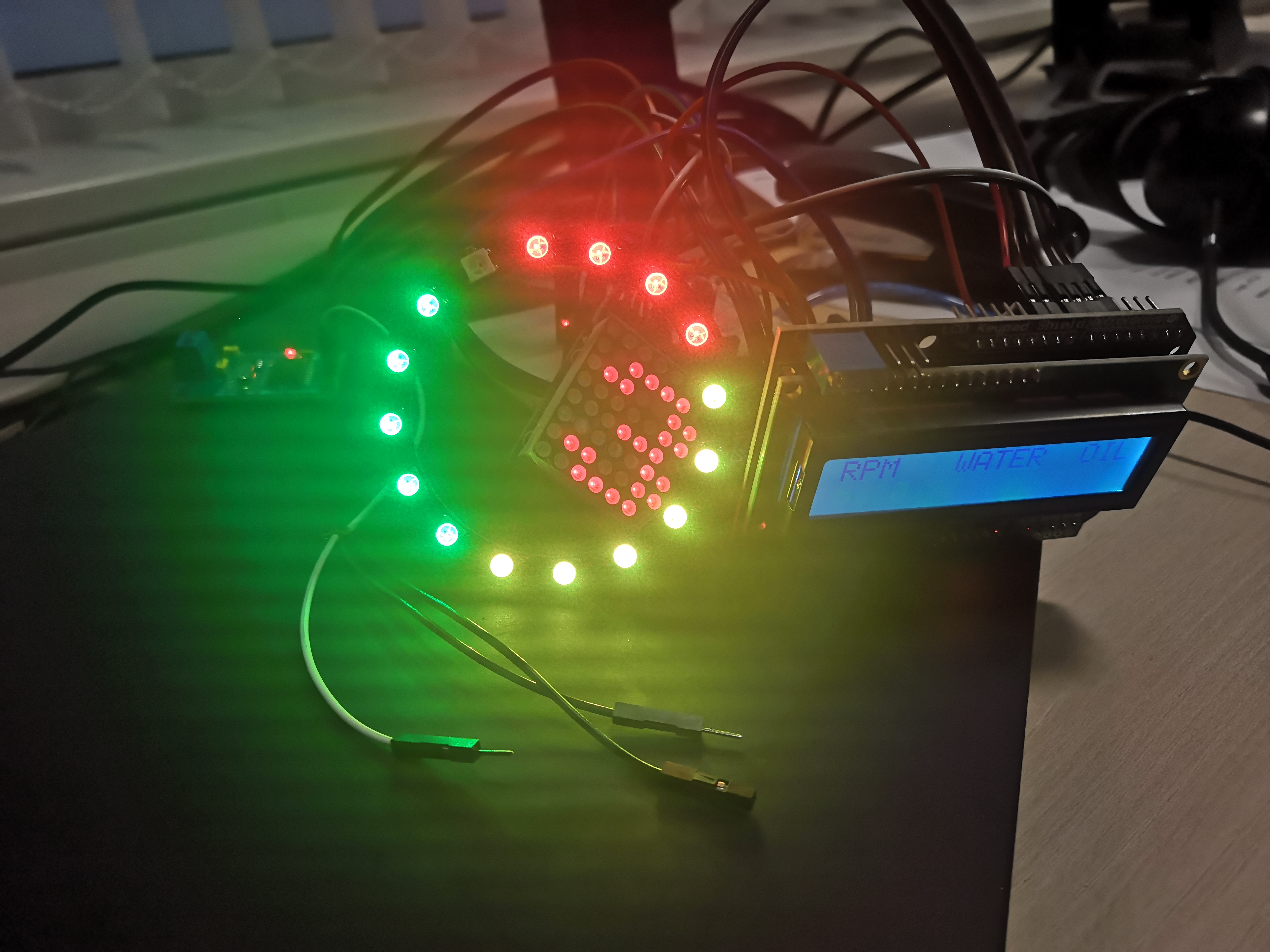
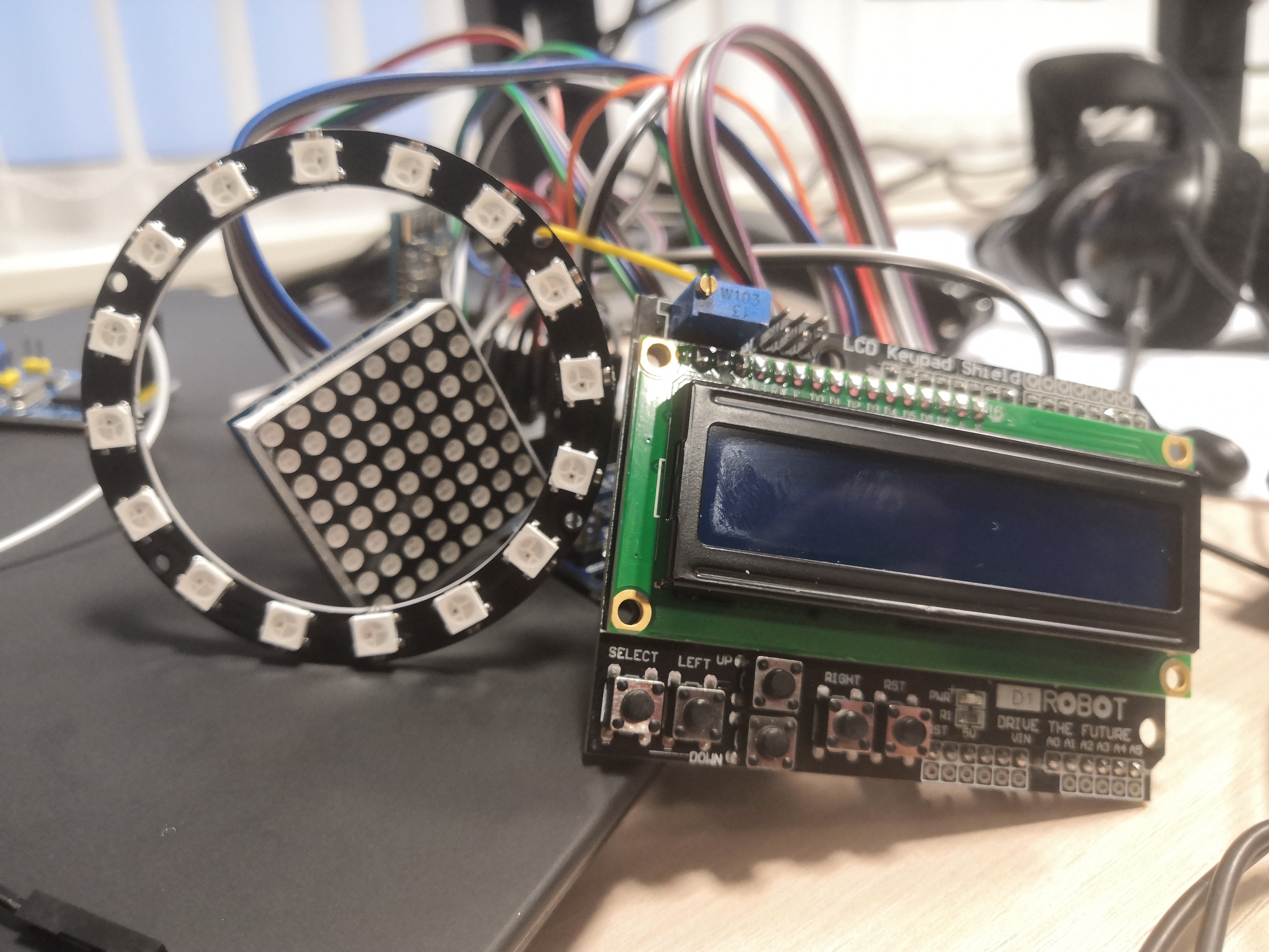
- RPM LED ring
- LCD with basic engine data (RPM, water coolant temp, oil temp..)
- Gear/shift indicator that reads the current gear from the shift lever on top of manual gearbox
During prototyping I use simulators of Arduino, because the progress in electrical scheme/setup was way faster than trial&error on a real hardware. I'm more an IT guy rather than an electrician.
AVR Simulator tools used
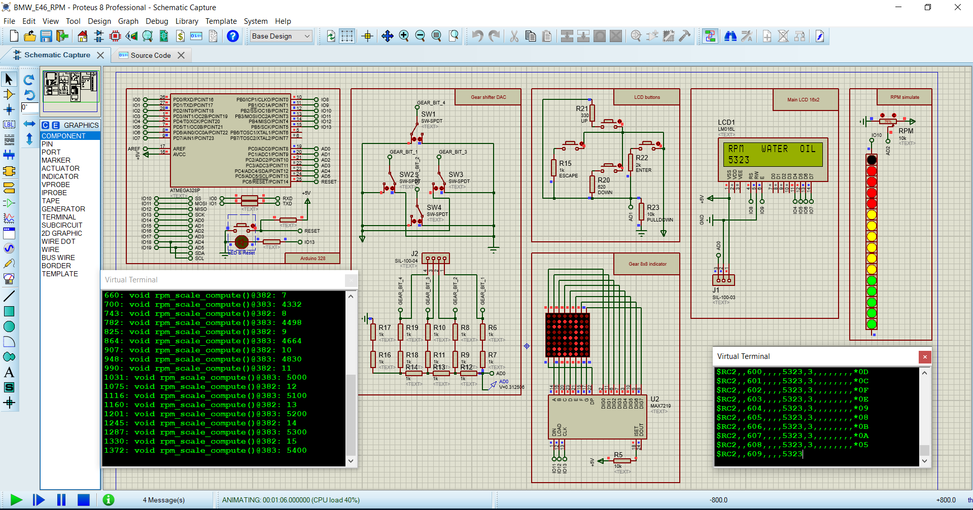
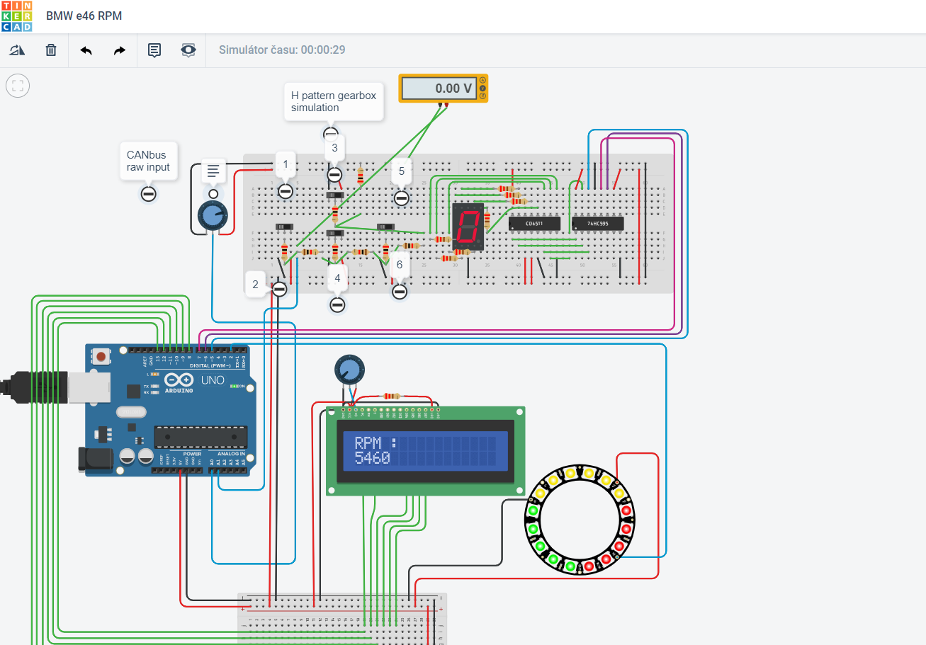
I started with Tinkercad for the very beginning, but realize there is no possibility to include 3rd party libraries, which I need at least for simulating the real hardware devices. I moved to VirtualBreadboard (the older 6.0.x version) which was way better and faster and also provide an integrated osciloscope. As it suddenly stop to work after some.NET update and I was unable to get it working again, I finally end up with Proteus. And I was astonished about its features. It is really a swiss army knife in microcontroller and circuit simulation and it provides also ton of debugging tools including I2C, SPI, oscilator, conditional code breakpoints and a lot more stuff including PCB designs and 3D models of the components used. Definitely recommended for "bigger" projects and pricing is also ok compared to how many features it has.
EXPANDED TECHNICAL DETAILS: Data Extraction & Display Principles
For a project like this, the Arduino cannot simply "ask" a vehicle's ECU for data. It must interface with the vehicle's communication network. In a real car, this is done by connecting to the CAN bus. For a simulator setup, an intermediary software tool like SimHub is used to extract live physics data (RPM, Gear, Speed, Oil Temp) from a running game and send it via a serial connection to the Arduino.
The Shift-Light LED Matrix Engine (TM1638)
Professional drivers use prominent LED strips as shift lights to avoid looking away from the track. A highly effective hardware choice for this is the TM1638 8-Digit LED / Button / 8-LED Array Board.
The Output Logic: The Arduino's main loop waits for incoming serial data. A host PC (running software like SimHub or, in the real-car case, processing CAN bus data) executes the mapping logic—for example, converting a car's RPM (0-8000) to a value for the LED bar (0-8). The Arduino then receives a simple command like "Light up 7 LEDs!" and updates the display instantly.
// Optimized code to set shift lights based on a command from the host.
void setShiftLights(byte numberOfLEDs) {
  // 1 = 1 LED, 3 = 3 LEDs, 8 = ALL WARNING LIGHTS FLASHING!
  module.setLEDs( (1 << numberOfLEDs) - 1 ); // Instant binary cascade execution.
}
Creating Complex 128x64 OLED Gear Indicators
Beyond simple shift lights, the dashboard needs to display critical numerical data like speed or gear.
- The Data Payload: The host software sends a structured string, e.g.,
G: 4\nS: 145\n. - The Arduino parses this string, separating values by the newline (
\n) character. - Using a library like
<Adafruit_SSD1306.h>, it can display the data with commands likedisplay.setTextSize(5);to create giant, easily readable text. - This system allows for dynamic feedback. For instance, if the host signals a reverse gear or a gearbox failure (e.g.,
currentGear = -1), the Arduino can change the display to a flashing 'R' or an exclamation point.
Typical Hardware Rig
- Arduino Uno/Nano/Leonardo (Any board works, but boards with native USB chips like the ATmega16u2 handle high baud rate serial streams very reliably).
- Host Software (e.g., SimHub for sim racing, or custom firmware for processing real vehicle CAN bus data).
- TM1638 LED Interface Module (Excellent for shift lights due to its integrated LEDs and 7-segment digits).
- A 0.96" I2C OLED Display or 4-Digit 7-Segment HT16K33 Backpack to act as a primary gear or data indicator.
Finished project tasks
- LCD with menu for configuring NeoPixel RPM colors and their ranges. Fully customizable and stored in EEPROM
- 8x8 LED matrix using standard SPI instead of software seen in LedControl.h library
- DAC for gears -simulated. A simple 4bit Digital to Analog converter to read 4 switches that will be mounted on the gear shift lever and based on which bits are High/Low displays correct gear on 8x8 matrix
- MCP2515 CANbus successfully connected to a car and values from ECU sniffed and translated to human readable values of RPM, throttle position and Coolant temp
- RaceChrono Bluetooth connection to Arduino to receive live data. Currently only Bluetooth2 is working as RFCOMM device. For Bluetooth4LE a more low-level configurable chip is needed to meet RaceChrono requirements (eg. ESP32/8266). I was unable to get it working with HM-10 breakboard and its Serial configuration only.
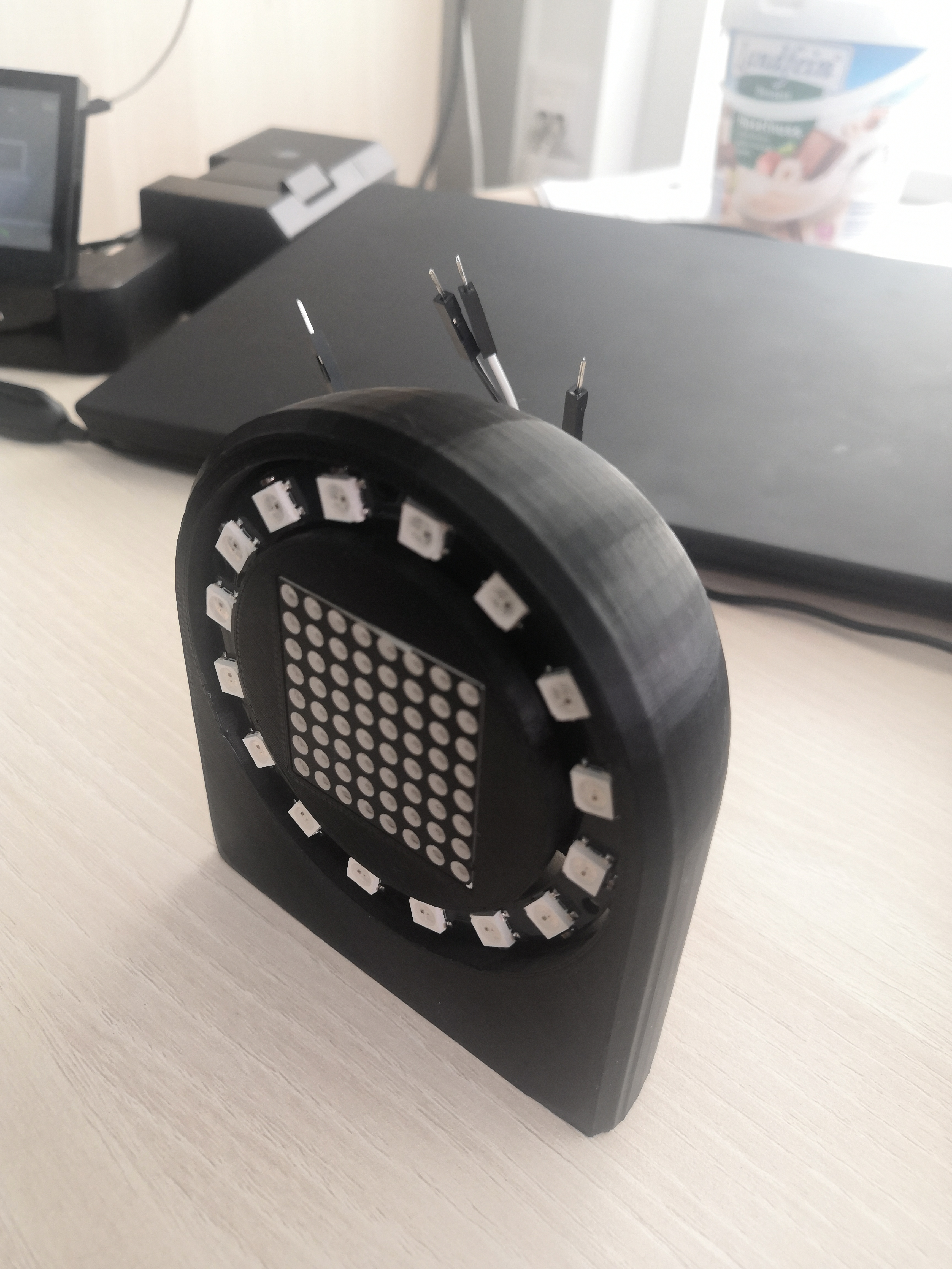
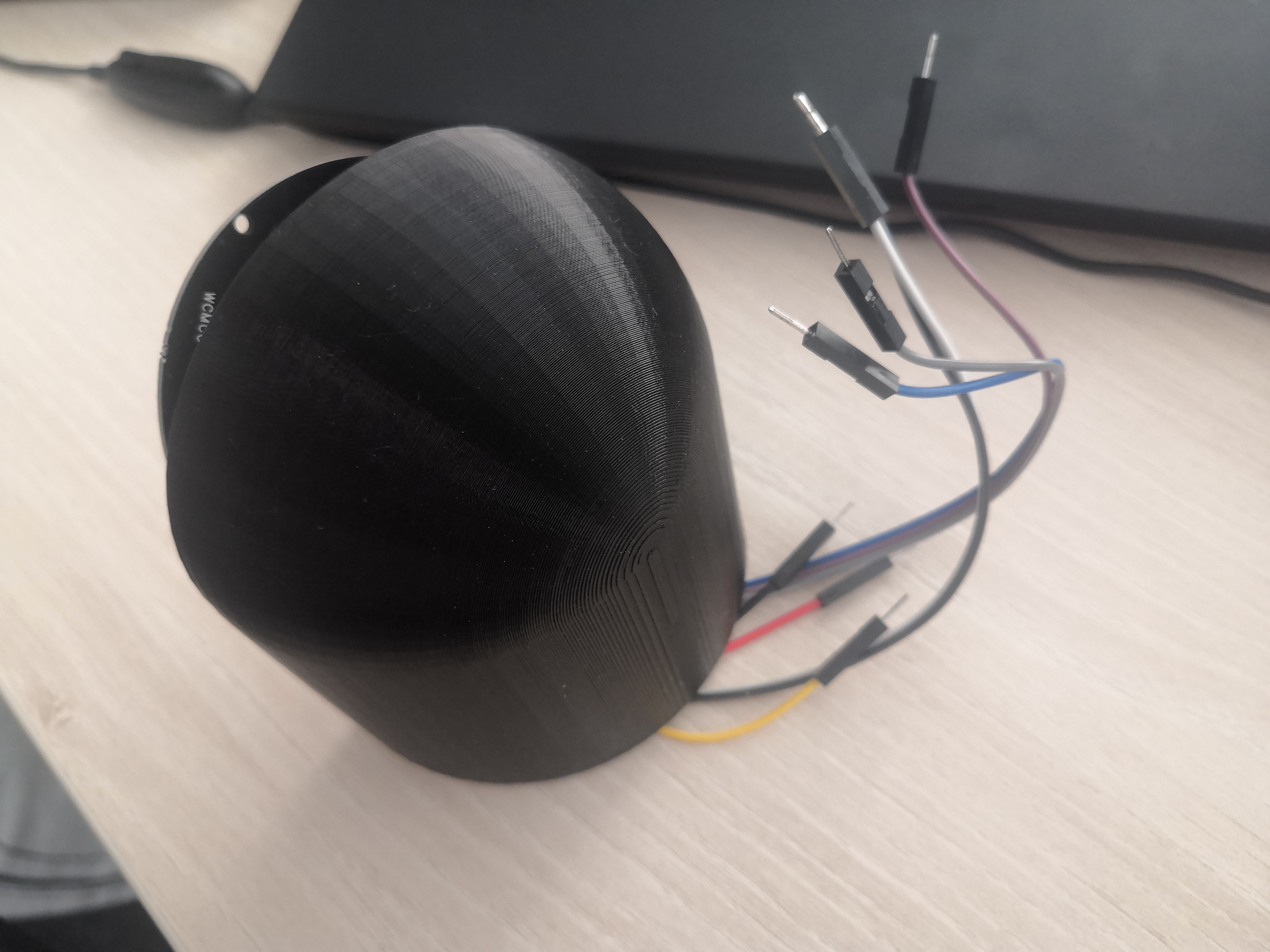
- Measured, create and 3D print the dashboard enclosure for Arduino components and displays. As I have no experience, this task was a challenging journey for me. The modeling was done in SketchUp and final print looks awesome to me. Everything align nicely. Big thanksto my former colleagues to utilize their own profi 3D printer. I already purchased my own Ender3 for future projects 😁.
Unfinished project tasks
- Inspect CANbus messages for additional interesting data to process
- Observe power consumptions and interferences when finally mounted in the car
Possible further ideas to implement
- dynamically controlling the engine fan via PWM based on the coolant temps. As the fan control unit in my car is dead I have currently only simple switch/relay for 100% ON or OFF.
- Oil temp is not available on CANbus for this DME, but can be read via service K-line. Not in focus currently, but some proof of concept solutions found based on sniffing the serial line while the original BMW service programs are running and displaying the Oil temp. UPDATE: a simpler option will be to read the raw temperature sensor coming to the ECU
- Compensate the brightness of displays based on a light sensor in addition to a user manual configuration. Would be nice to have automatic dimming between day/night conditions.