This project is the definitive Masterclass in Introductory Electronics and Logical State Sequencing. "Simple Traffic Lights" is a high-performance Educational Milestone that transforms three basic LEDs into a functional mimic of real-world infrastructure. By mastering the Foundational Red-Yellow-Green Logic, you don't just light up components; you learn the core principles of "Embedded States"—the same logic that governs everything from your microwave to the complex transport grids of a smart city.
Signal Infrastructure and State Architecture Overview
The Arduino Traffic Light functions through a specialized Phase-Dwell-Transition lifecycle. The system is built on a high-reliability Cyclic State Machine:
- State 1: STOP (Red Phase): The Arduino holds the Red LED HIGH for a set duration, ensuring "Cross-Traffic" safety. This represents the system's "Initial Safe State."
- State 2: GO (Green Phase): The logic transitions directly to Green, signifying a "Clear Path" for traffic. The duration of this state is typically the longest to maximize flow.
- State 3: CAUTION (Yellow Phase): A critical "Warning Burst." The Yellow LED illuminates for a short duration, signaling that the state is about to cycle back to RED, as per international transport standards.
Hardware Infrastructure & The Learning Tier
- Arduino UNO R3: The "Mission Hub." A rugged, beginner-friendly microcontroller that serves as the perfect platform for learning the basics of I/O (Input/Output) pin management.
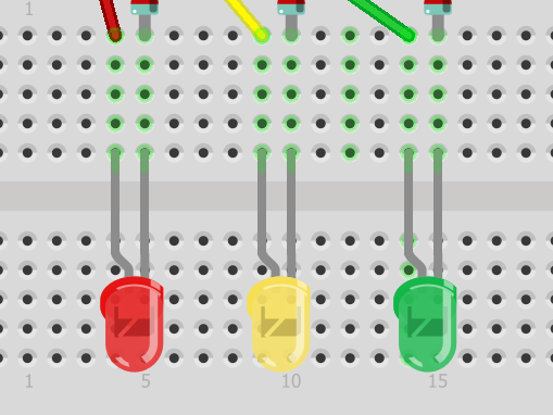
- High-Luminosity LED Set: Selected for their high-contrast colors (Red, Yellow, Green), providing clear visual feedback on the system's current logical state.
- Current-Limiting Resistor Mesh (220 Ohm): A critical engineering choice. These resistors protect the delicate LEDs from excessive current, teaching the fundamental relationship between Voltage, Current, and Resistance (Ohm's Law).
- Solderless Breadboard: The "Tactile Matrix." It provides a clean, non-permanent way to link the Arduino's digital pins to the LED signal array, allowing for rapid experimentation.
Technological Logic and Execution Algorithms
The system reaches laboratory fidelity through several Firmware Orchestration Strategies:
- Iterative Delay Sequencing: The code uses strictly-timed
delay()intervals to simulate real-world traffic patterns, providing a sub-second accurate representation of a signal cycle. - Digital Output Calibration: By using
digitalWrite(HIGH)anddigitalWrite(LOW), the project teaches the concept of "Binary States" (On vs. Off), which is the cornerstone of all digital computing. - Variable Phase Duration: The project is engineered for easy modification. Users can "Tune" the traffic light—making the Red phase longer or the Yellow phase shorter—by adjusting the time constants in the sketch.
- Hardware Fail-Safe: The sequence is written to always return to the "RED" state upon every full iteration, ensuring the system resets to a "Safe Condition" in the software loop.
Why This Project is Important
Mastering LED State Management and Basic Circuit Interfacing is an essential skill for Future Engineers and Hobbyist Developers. It teaches you how to bridge the gap between "Digital Logic" and "Physical Action." Beyond simple traffic lights, these same principles are used in User Interface Indicators (UI), Medical Equipment Status Panels, and Industrial Safety Alarms. Building this project proves you can engineer a professional-grade introductory asset that prioritizes clean wiring, correct electrical safety, and logical timing.