Introduction
Connecting an LCD to an Arduino can sometimes be a bit tedious due to the number of wires and components required, such as potentiometers and resistors.
To streamline this process, I've created a custom LCD Breakout Board that simplifies these connections.
This board includes :
1. Two potentiometers to:
a. Control the backlight brightness
b. Adjust the contrast (text brightness)
2. Pins for common positive and negative terminals
3. Separate Data pins
Making it easier to hook up your LCD to an Arduino using just a few jumper cables.
(NOTE - You don’t need any libraries to use this breakout board.)
In this tutorial, I will walk you through how to make and then use this breakout board to quickly set up an LCD with your Arduino.
Project Overview
The "Custom LCD Interface Board" is an essential developer tool designed to eliminate the common "spaghetti wiring" associated with industrial 16x2 Alphanumeric Displays. Standard parallel LCDs based on the HD44780 controller require up to 16 connections, including sensitive analog biasing for contrast. This project consolidates these requirements onto a compact Perf Board, providing integrated potentiometers for both backlight and contrast control. By reducing the interface to a standardized 8-pin header, makers can integrate visual feedback into their Arduino projects in seconds rather than minutes.
Technical Deep-Dive
- Dual-Potentiometer Biasing Circuit:
- Contrast Control ($V_0$): Pin 3 of the LCD requires a specific bias voltage to make the liquid crystal pixels visible. The 100k potentiometer acts as a precise voltage divider between 5V and GND.
- Active Backlight Dimming ($A/K$): While many projects hard-wire the backlight to 5V, this board includes a second 100k potentiometer. This allows the user to dim the display for night-time use or to reduce the overall power draw of the system.
- 4-Bit Parallel Optimization: To conserve Arduino I/O pins, the breakout board is wired for 4-bit nibble mode. This configuration allows the HD44780 to receive 8-bit instructions in two consecutive 4-bit chunks (using Data pins D4-D7). This saves four digital pins on the Arduino, allowing them to be used for other sensors or actuators.
- Bus Consolidation & Signal Integrity: By soldering the power (VCC) and ground (GND) lines into common rails on the perf board, the board significantly reduces electromagnetic interference (EMI) and prevents accidental "floating" connections that often cause garbled text on breadboards.
- Physical Engineering & Durability: The project includes mechanical Spacer Screws. Parallel LCDs are heavy components; without direct support, the weight of the display often stresses the header pins, leading to intermittent connection failures. The spacers transfer this mechanical load directly to the perf board, ensuring a robust, "lab-ready" instrument.
Workflow & Reliability
- The "Prototyping Standard": This board becomes a semi-permanent addition to a maker’s toolkit. Instead of rebuilding the LCD circuit for every project, the 8-pin interface (5V, GND, RS, EN, D4-D7) creates a plug-and-play standard across different microcontrollers.
- Code-Free Debugging: Because the contrast is handled via on-board hardware, developers can instantly verify if a "Blank Screen" is a software bug or simply a contrast setting—without needing to modify a single line of code.
- Universal Header Layout: By using standard male/female headers, the board can be mounted directly onto a breadboard for temporary use or connected via a ribbon cable for a professional case-mounted display.
Steps
Step 1: Prototype Before You Solder
Before you finalize your design by soldering the components onto the perf board, you can first try prototyping the circuit on a breadboard.
You can use this circuit diagram for reference:
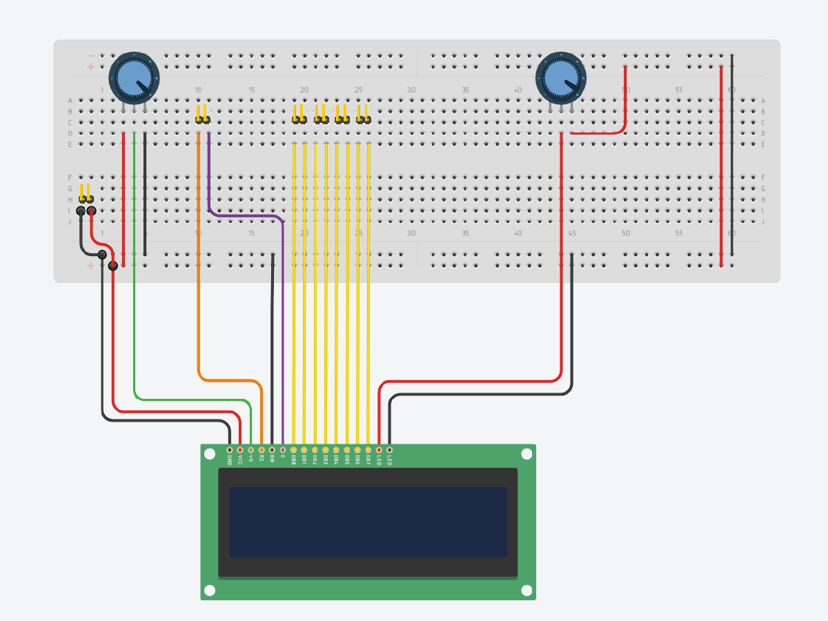
This allows you to test the connections, make adjustments, and ensure everything functions as expected.
During this stage, you can experiment with different configurations, such as adjusting potentiometer values, modifying the layout, or adding/removing functionality to better suit your specific needs.
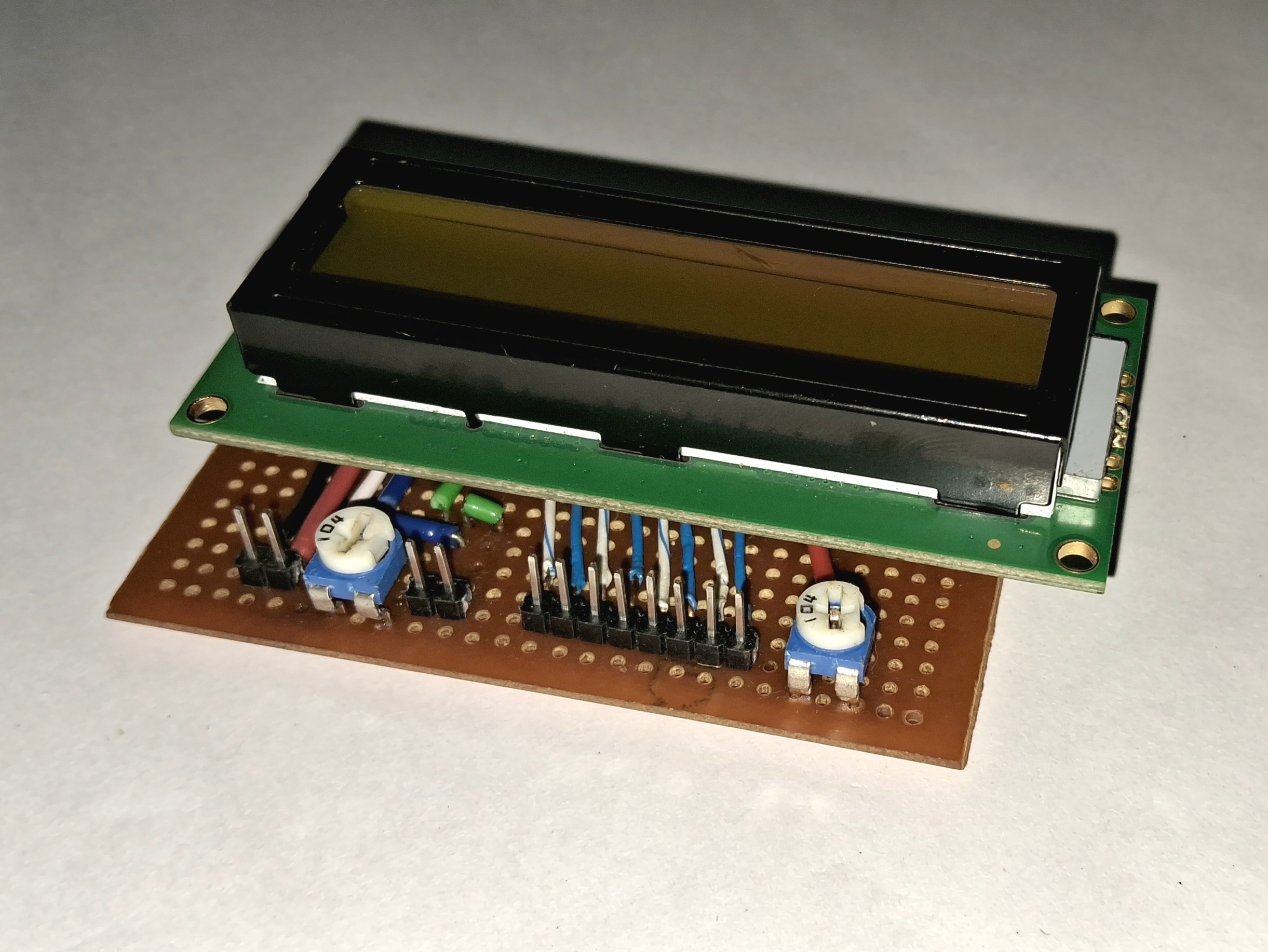
Step 2: Solder the components on the perf board
Once you're satisfied with the setup, you can then proceed to solder everything onto your perf-board while keeping the connections clean and simple.
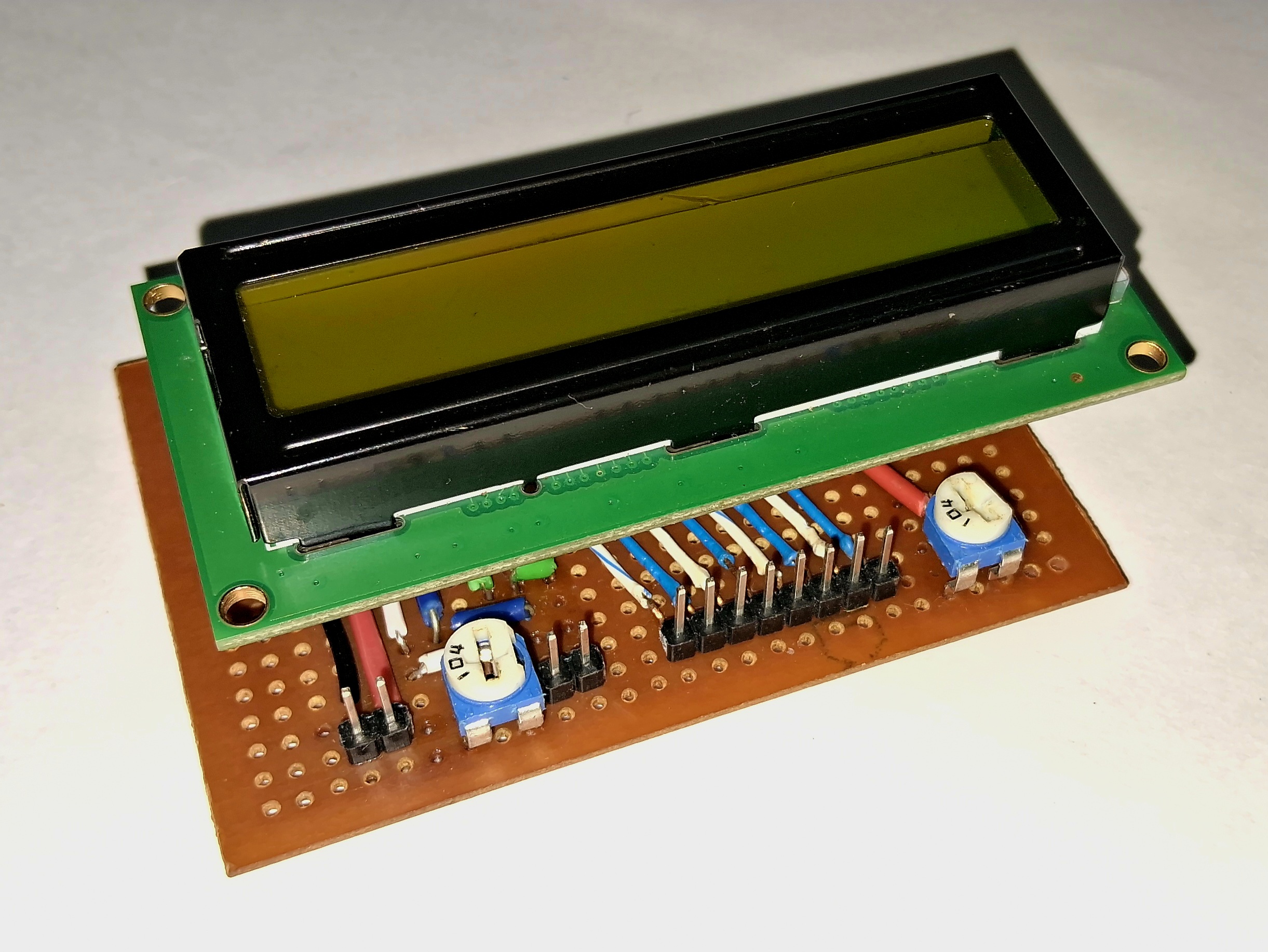
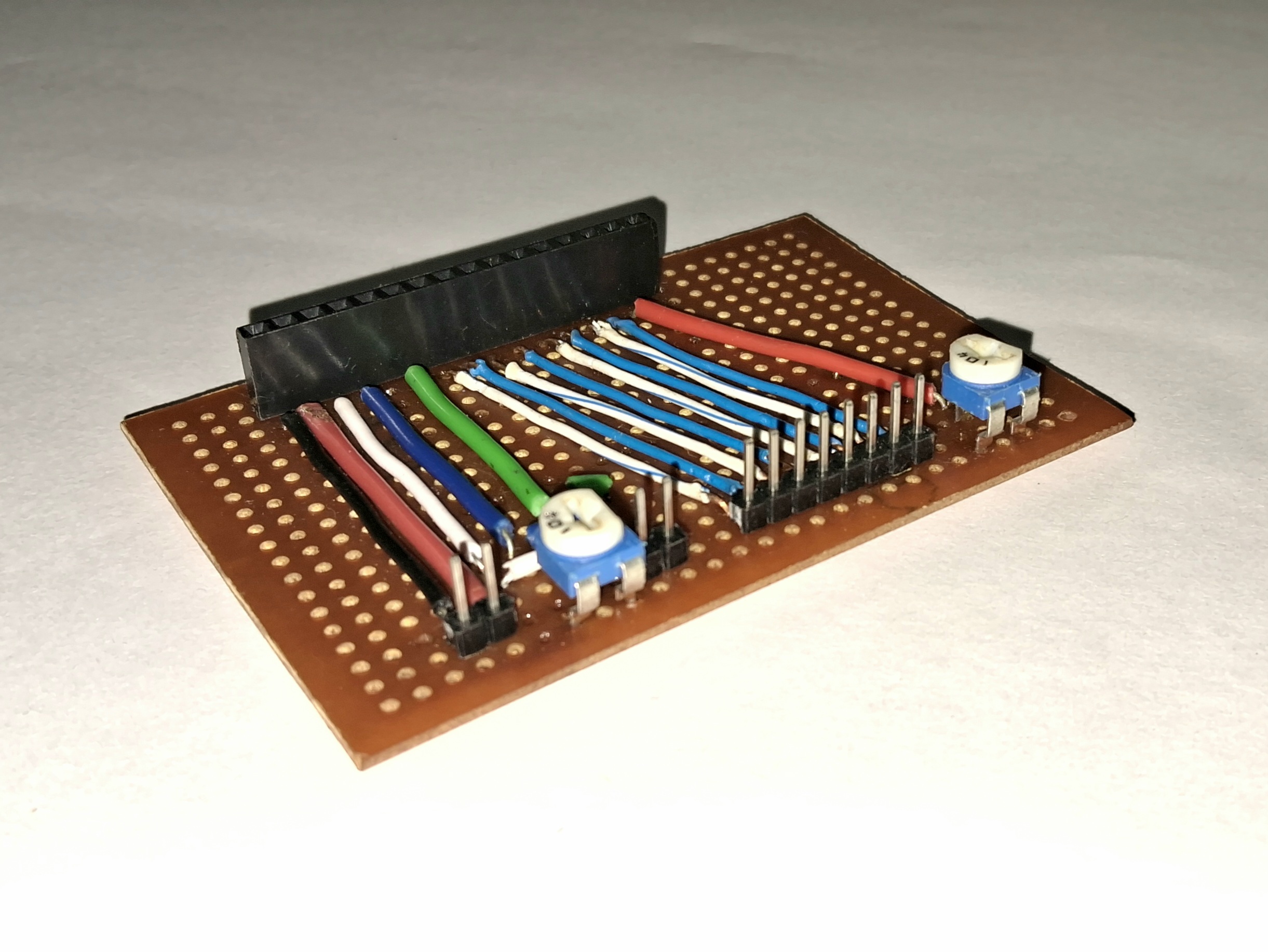
Optional: Mark Pins for Easy Identification
To make the wiring process easier and avoid confusion, you can use a permanent marker to label the pins on the breakout board. Simply mark the pin names (e.g. VCC, GND, RS, EN, D4, D5, etc.) directly on the board or near the pin headers. This step is optional, but it can save time and reduce errors during setup, especially if you plan to disconnect and reconnect components frequently.
Optional: Add Spacer Screws for LCD Support
To provide additional support and stability for the LCD, you can add spacer screws of appropriate size to the board. This will help prevent the LCD from shifting or flexing during use. When adding the screws, ensure that you carefully drill the holes in the board without damaging any existing connections. Be mindful of the placement to avoid interfering with the circuit's functionality. This step is optional but can improve the durability and reliability of your setup.
Optional: Design a Custom PCB
For a more refined and durable circuit, you can design a custom PCB. This allows for a cleaner layout and consistent connections. Use PCB design software like Eagle or KiCAD to create your design, and then have it manufactured and assembled.
Testing:
Step 1: Verify Connections on the Breakout Board
Ensure your custom LCD interface board is ready, with all components properly soldered and connected. Check for any possible shorts between pins.
Step 2: Connect the LCD to the Custom Interface Board
Attach the 16x2 LCD display to the breakout board.
(Optional: Tighten the spacer screws to provide support to the LCD)
Step 3: Connect the breakout Board to the Arduino
Using jumper wires, connect the following pins from the breakout board to the Arduino:
VCC from the board to the 5V pin on the Arduino.
GND from the board to the GND pin on the Arduino.
RS to Arduino pin 12
EN to Arduino pin 11.
D4 to Arduino pin 5.
D5 to Arduino pin 4.
D6 to Arduino pin 3.
D7 to Arduino pin 2.
Step 4: Upload the Code
Upload the given code to your Arduino using the Arduino IDE.
Step 5: Power Up and Adjust Contrast
Power up your Arduino by connecting it to your computer or a power supply. Use the potentiometers on the breakout board to adjust the contrast of the LCD until the text is clearly visible.
Step 6: Test Your Setup
The LCD begins with a start-up message (“LCD Custom Board”) followed by a loading animation (“Loading...”). It then runs a scrolling test where a solid block character moves across both lines of the display, visually checking all character positions (pixels). After the test completes, the screen shows the message “Test Completed”. If everything is working correctly, you've successfully used your custom LCD breakout board to simplify the LCD-Arduino connection!
Final LCD Output:
Watch the video to see the custom LCD interface board in action.
Troubleshooting:
No Display: Check all connections and ensure the LCD is properly seated on the breakout board.
Dim/No Text: Adjust the potentiometer to change the contrast.
Conclusion:
By using this custom LCD breakout board, you can save time and reduce the complexity of connecting an LCD to your Arduino. This project is perfect for those who frequently use LCDs in their Arduino projects and want a more streamlined setup process.
Feel free to modify and expand upon this design to suit your specific needs!