Introduction
This project is my entry to the Arduino / Distrelec Automattion Contest of 2018. It is based on a skating robot I designed earlier this year and published as an idea. The "only" thing I needed to do was do develop a version which can be controlled via Blynk and then add more functions once there is a good user interface. Of course thing never are that easy and I write something about the project below.
The aim was to have more functions, like autonomous mode, but I needed to focus on haveing a working robot and things as neat as possible in the beginning of September to fit the contest dead line. I decided to instead add the feature with a servo and ultrasonic sensor and a simple user interface in my Blynk app. Autonomous moving is the next thing I will jump onto. I am anyway convinced that my robot in many ways is unique and maybe show one way of combining walking with wheeled propulsion.
The Concept Behind
Robots can often fall into two categories, wheeled or walking. A wheeled robot is simple of design (basically a remote controlled car) and fast moving. Legged robots are more of an engineering challenge since they need complex programming in order to move their limbs, the challenge itself was one reason for me personally to develop my KITtyBot. The advantage with the legged type is the possibility to climb over obstacles and walk up and down stairs. This can be essential for rescue missions within buildings. But on flat ground the walking robot is slow compared to a wheeled. Then of course the concepts can be combined in many ways in order to have best from two worlds. A wheel robot with an advanced suspension can negotiate obstacles and eventually the "suspension" can be more like "legs" and allow some walking or climbing.
My project evaluates a robot with wheels that are passive, i.e they lack propulsion. There is instead a servo allowing for angling the wheels, basically like the front wheels on a car. Moving is done by skating (or maybe like paddling a canoe), i.e. using the possibility to angle the wheel and push forward using leg movements. This allows for a rather fast and energy efficient movement, at least compared to ordinary walking. The advantage over a conventional wheeled robot with "legged suspension" is that there is not need for motors driving the wheels. The robot can any time revert to walking.
Much of the design is similar to the robot KITtyBot I published here on the Project Hub. It uses the same Inverse Kinematics to move the feet and in case it does walking it uses the same walking gaits that I developed for KITtyBot. The new part is the "roller skates" added to the feet. The contact point of the wheel is located where the tip of the foot was on KITtyBot.
Technical Deep-Dive: Inverse Kinematics & Skating Heuristics
The robot is a rigorous implementation of Hybrid Robotic Locomotion. It utilizes a mathematical model to calculate the necessary joint angles $(\alpha, \beta, \gamma)$ required to place each foot-coordinate $(x, y, z)$ in 3D space. This Inverse Kinematics (IK) Logic-Engine translates linear joystick-vectors from the Blynk app into coordinate-deltas. The core innovation is the "Skate-Gait," where the legs push laterally while the foot-servos adjust the wheel-angle, generating forward momentum through passive-wheel physics, mimicking human ice-skating mechanics.
Management of the 16 high-torque MG996R servos is handled via I2C using a PCA9685 driver. This 16-Servo Orchestration leverages the driver's 12-bit PWM resolution for sub-degree accuracy. A software-defined "Center-Point" calibration array $(\text{servodeg0}[16])$ is applied to harmonize the resting pose across all mechatronic joints.
Building the Robot
Print the parts according to the supplied files. Take som time to look at the pictures and figure out how to assemble the parts before starting.
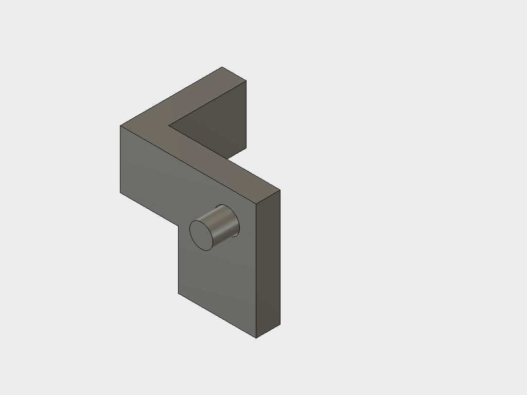
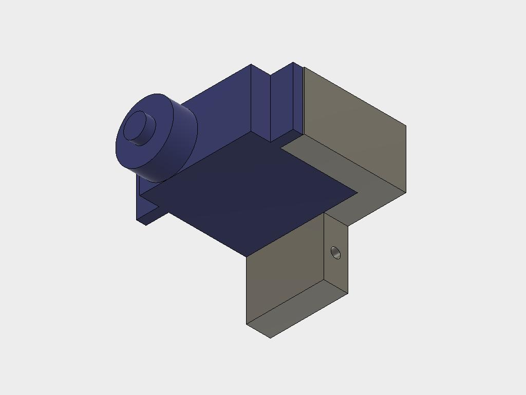
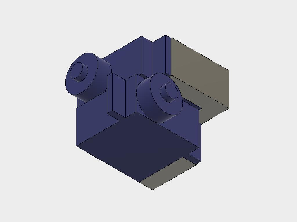
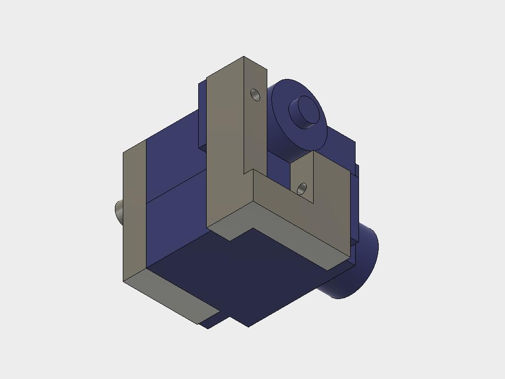
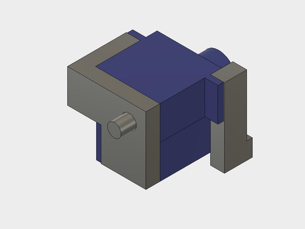
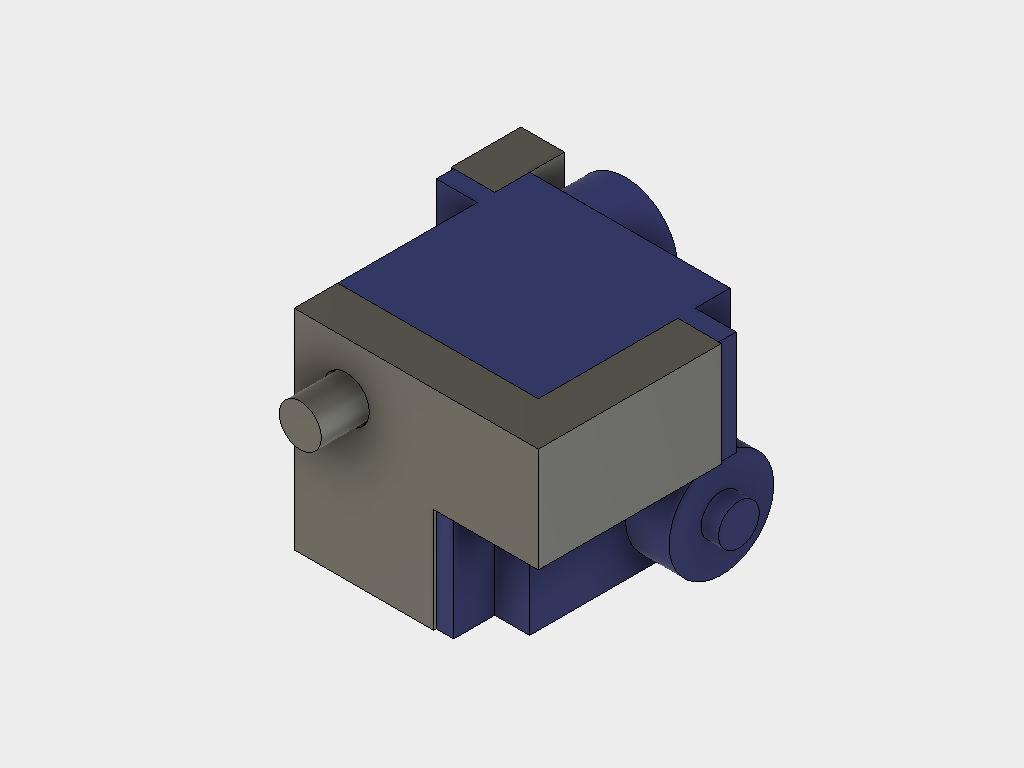
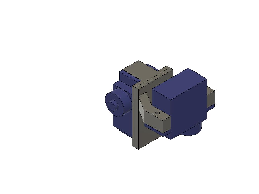
The hip joint should be assembled first. I have developed the design from KITtyBot by adding some more 3D printed parts. In doing so I also had to redesign the body, the new hip joint reauires a few mm more space. If you happen to have parts for a KITtyBot lying around or want ot convert one into this robot you can do that. The form factor will be the same once everything is assembled
Note that there are two versions called fl/rr (front left / rear right) and fr/rl (front right / rear left). Two sets of each kind are needed to make four hip joints. Make sure that you have the parts sorted. Apart from these four pins are needed and finally a new body. The legs and bumpers from the original KITtyBot are kept.
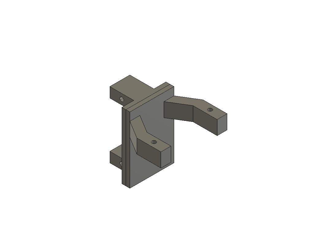
The pictures below show assembly of the joints. The step by step instruction in the figure below show how to do the fl/rr joint. The other joint should be straight forward once you have used up half of the parts. :)
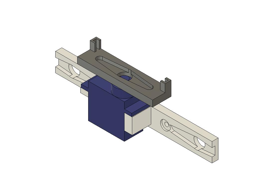
Next is the foot joint. This also consist of two 3D printed parts and two servos each. There are four parts each called foot first and foot second. They are not separated into fr/rl and fl/rr version since will be altered by how the servos are mounted. The pictures below describe the mounting sequence.
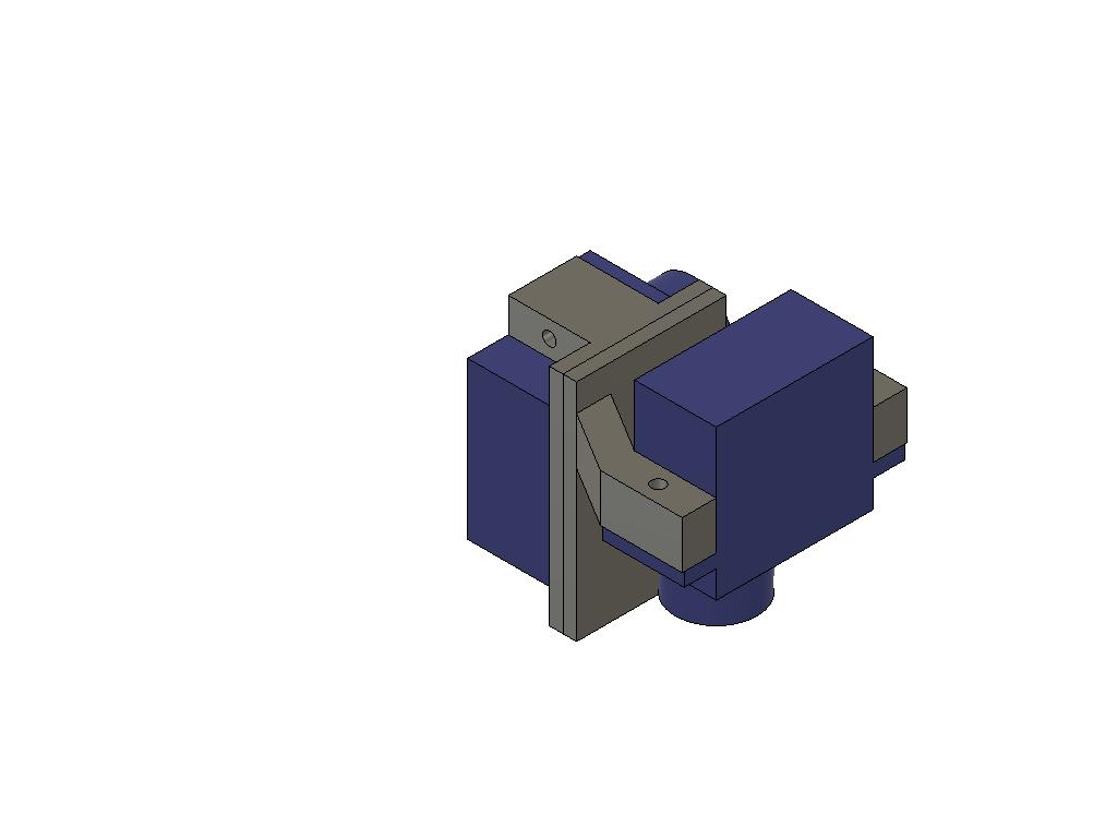
After doing this the legs can be completed. Before proceeding it is good idea to make sure that all 12 servos are centered. The best way is to assemble the electronics, see below, connect all servos and the load the code. When the Arduino is started up all servos will center (command signal 90 degree).
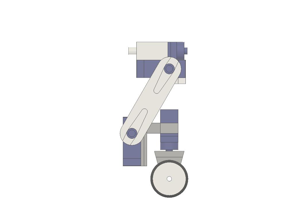
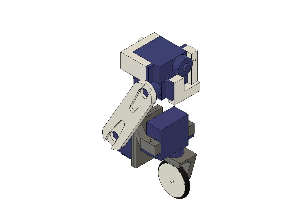
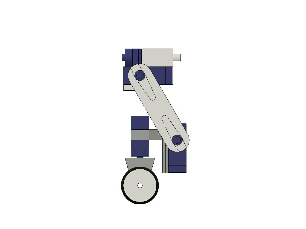
The parts for the upper limb, thigh, and the part where the wheel is attached, called foot, have recesses that fit together with the servo horns that normally are delivered together with the servo. Glue horns into the recesses. Make sure to use a glue that works for joining the 3D printed material and the nylon plastic that the horn is made of. The glue gun I used worked fine, some better CA glues do also.
The complete leg assemblies should look like in the pictures below. First attach the two servo assemblies with the thigh part. The thigh is angled 30 degrees from vertical. This will be achieved when the centre of the wheel servo is in line with the centre of the lower hip, alpha, servo. Make it as close as possible and fine tune the centre positions in the code once everything is assembled (see below).
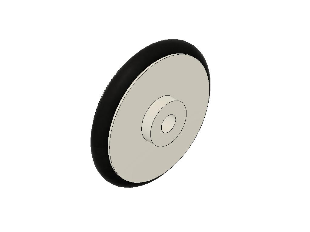
The foot part can then be assembled to it's servo. The wheel is made from the 3D printed rim with an o-ring as "tire". The wheel is mounted to the foot with M3 screws and nuts. Use two washers between the foot and wheel in order to make it roll as smoothly as possible.
The legs can then be assembled with the body. The bumpers should have servo horns glued into their recesses. The best way is to attach the servo drive into the bumpers' as close as possible to the desired angle, see below, and secure them with screws. A complete bumper with two legs can then be mounted onto the body and the bumper being secured with servo screws. Note: All screws supplied with servos will be needed to assemble servos onto the hip and foot joints. You probably have some extra mounting screws lying around, at least it is a good advice to have spare servos since they easily break.
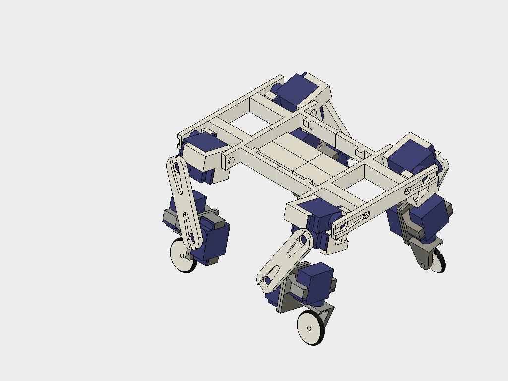
The picture below show the assembled robot. The bread board for the electronic should fit on top of the robot. Attach the battery under the "belly" with velcro. It can be removed for charging, or replaced by a freshly charged, and also the centre of gravity can be adjusted by moving the battery around.
Engineering & Implementation: 3D-Printed Structural Forensics
The robot utilizes high-density 3D-printed hip joints (versions $fl/rr$ and $fr/rl$) to handle the torque-load of the MG996R servos. This involves integrating M3-screw reinforcements and CA-glue bonds between Nylon servo-horns and PLA/PETG surfaces to prevent mechanical shear under stress, a process known as Hip-Joint Flex-Mitigation.
The implementation allows for dynamic center-of-gravity (CoG) adjustments by shifting the LiPo battery along the ventral-chassis using velcro. This Kinetic Balance Calibration involves verifying the symmetry of the leg-extension gait to ensure the robot skates in a linear-harmonic vector without unintended yaw.
Adding an Ultrasonic Sensor and Servo
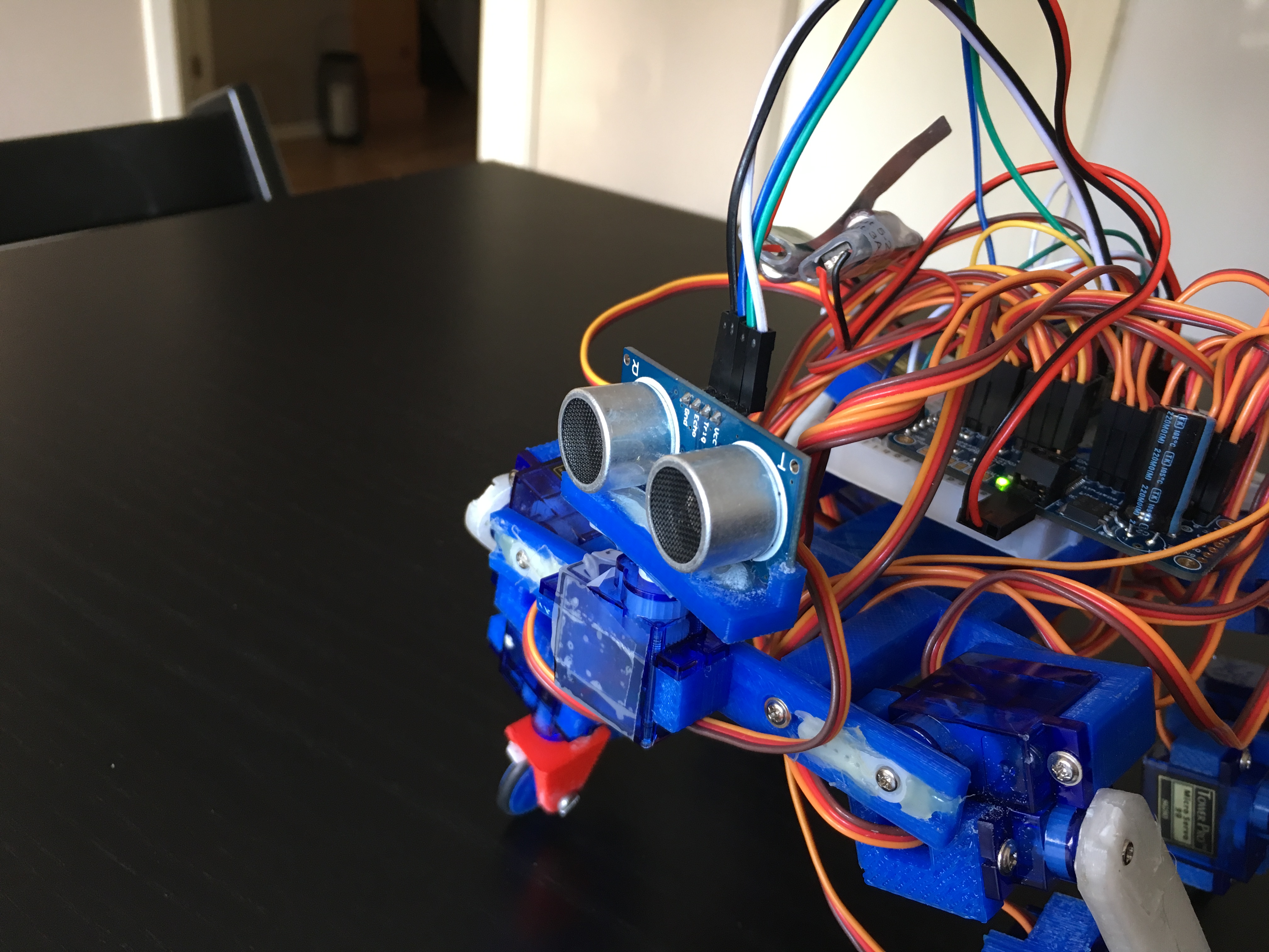
The goal with this project was to have autonomous navigation by help of an ultrasonic sensor, HC-SR04, mounted on a servo. Well, the hardware in terms of 3D printed parts are ready and the function itself has been tested together with the electronics. I simply add these items as they are at the time of contest dead line and you can choose to assemble them and play around a little, and maybe write code for autonomous navigation and publish. :)
The front bumper should be replaced by the US bumper and the sensor holder should be assembled on top of a 17th servo. The servo itself fit into the front bumper. When doing all this the centre of gravity moves forward. It is good idea to move the bread board on top of the robot to the rear.
For autonomous mode, an HC-SR04 sensor is mounted on a $17\text{th}$ servo-node. This Acoustic ToF Navigation involves a voltage-divider circuit on the Echo signal $(\text{5V to 3.3V})$ to protect the MKR1000's logic-ports while calculating obstacle-distance through high-precision pulse-timing diagnostics.
Hooking Up the Electronics
Connecting the components is quite straight forward. Some things are however worth to mention. Before going any further I feel obliged to write something about LiPo batteries (a disclaimer I also wrote on my previous project KITtyBot).
I use a completely unprotected LiPo battery. This can be risky, the major hazards is to dis-charge it too fast or too deeply. The first hazard is avoided as long as it isn't accidentally short-circuited. A normal R/C battery has a discharge rate of 25 C which in this case allow for 12 A. The two UBECs will prevent it from being higher than 2 to 3 A each in any circumstances. The second hazard is prevented by the fact that the UBEC cannot supply voltage to the servos and the MKR if the battery voltage goes down to 6 V, which happens to be the limit for low voltage. To add surveillance a voltage indicator is fitted in the Blynk app. The KITyBot had an active voltage surveillance that put the robot to rest but it is not needed since the robot will stop working by itself before the voltage goes too deep.
And finally I must stress that the batteries should be charged with a purpose built charger and handled with usual care, never leave charging unattended. The battery should be detached from the robot (use velcro to mount it) and charged inside a fire proof bag or at least with a safe distance from flammable materials so a fire can be contained and not spread. Also store your batteries safely.
If you are not familiar with LiPo batteries consult a local R/C hobby store and buy batteries together with a suitable charger and possibly a fire proof bag/container for charging and storage. These items are often full of warning signs. Read them and use your own good judgement. :)
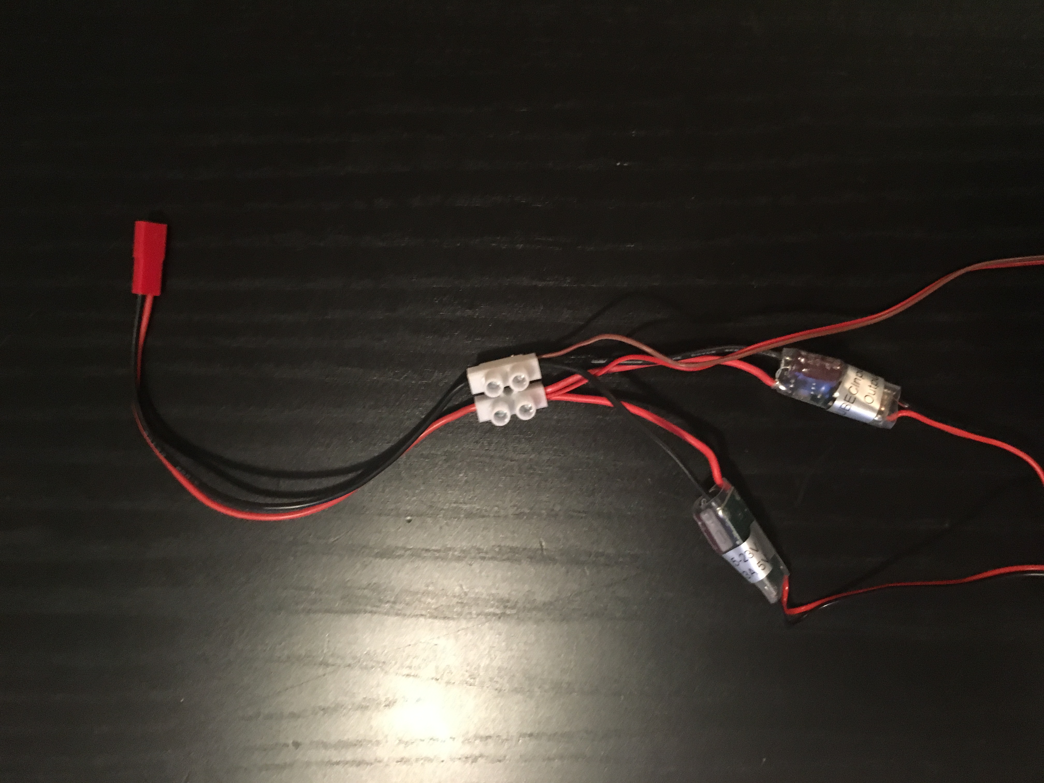
Connect the two UBECs to a battery lead. Also have two other wires feeding directly from the battery side. In my case these "two wires" was a scrapped servo cable with the signal (yellow or white) lead removed. It the fitted neatly onto a male-male header on the breadboard. It then became similar to the power out lead from the UBEC.
As shown on the schematics one power supply, UBEC 1, feeds the Servo Controller. The other, UBEC2, is connected to the "upper power rail" on the breadboard feeding the MKR. This rail can later be used to power more 5 V devices if needed, see below. The battery power (in my case the stripped servo cable) is connected to the lower power rail. From this the A1 pin is fed via two resistors to measure battery power. Via the two resistors the battery power is scaled down so 10.6 V converts to 3.3 V, giving a considerable margin to the maximum battery voltage of 8.4 V.
Technical Deep-Dive: Power-Rail Stability & IoT Diagnostics
Managing 16 servos during high-load skating maneuvers requires massive