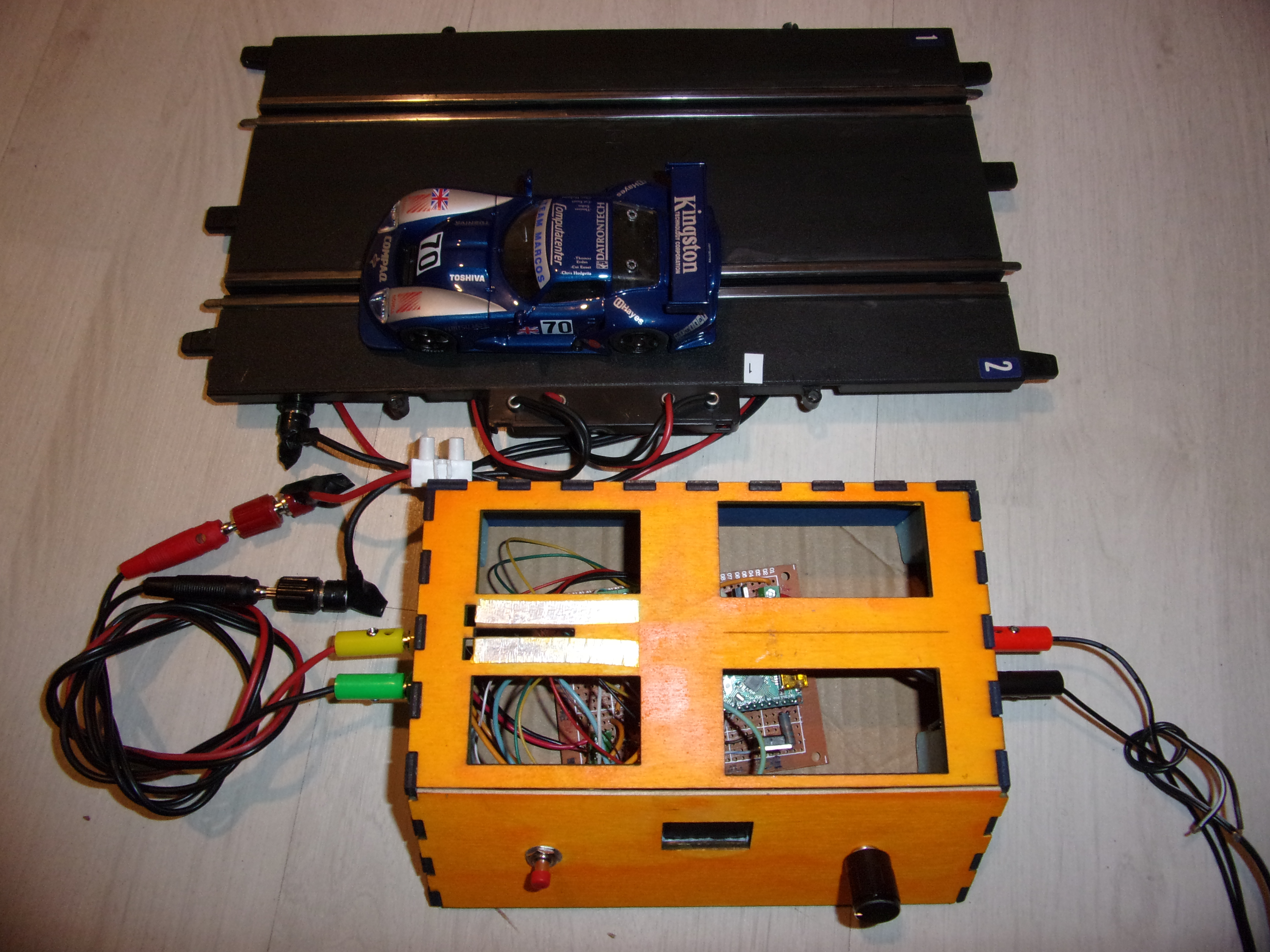
With this project I wanted to create a table test bench for Slot Cars, controlling the power of the engine using PWM using a rotary encoder. The bench can also be used to directly control a car on the track (ghost car type).
The bench is powered by 12V.
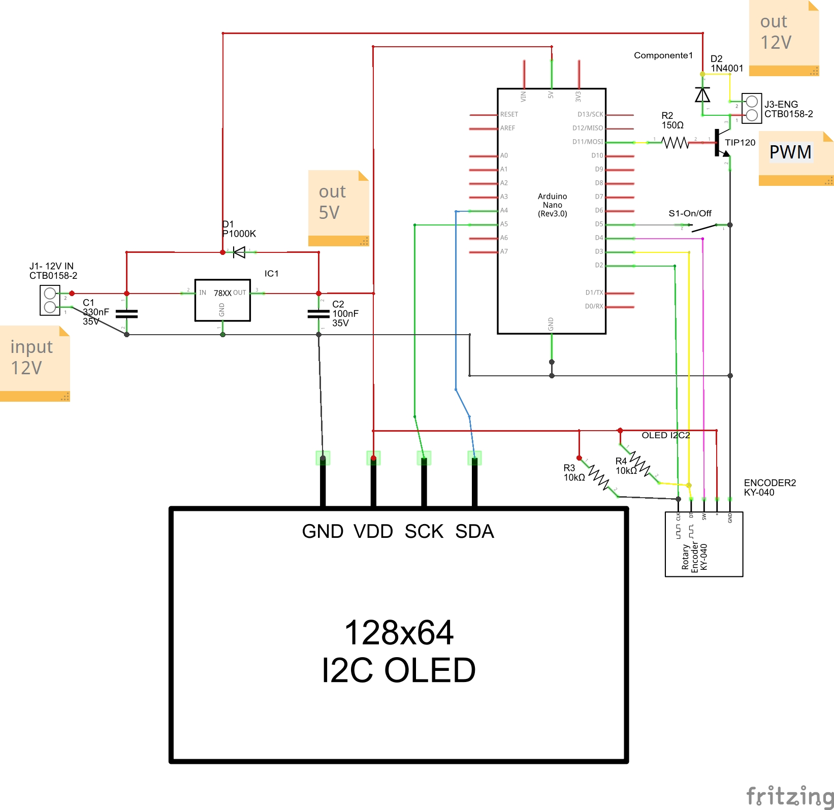
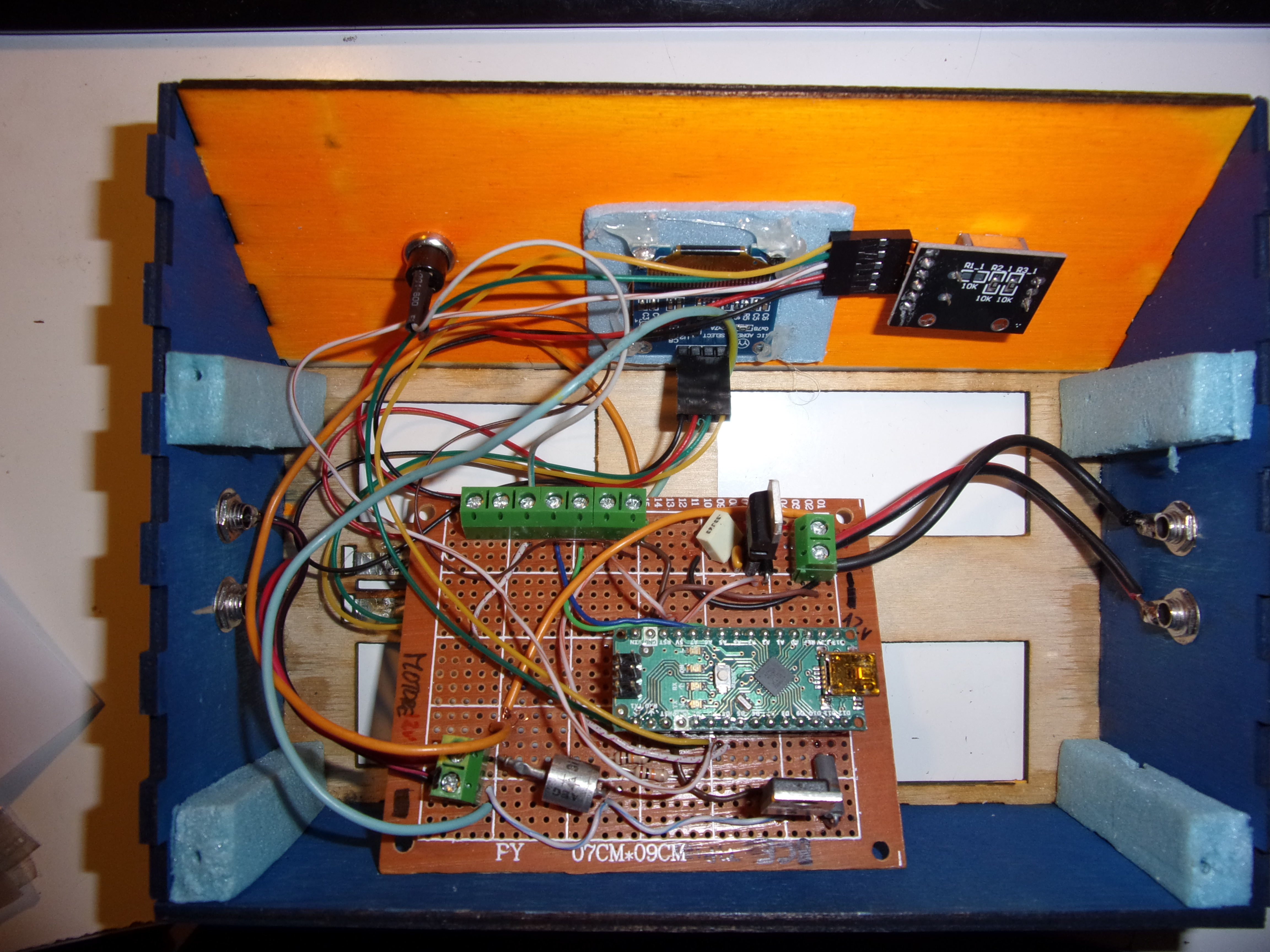
Immediately after the power supply there is the 5V stabilized circuit to power Arduino.
Be careful with this way of powering Arduino via the 5V PIN. You risk damaging it if it is not done correctly.
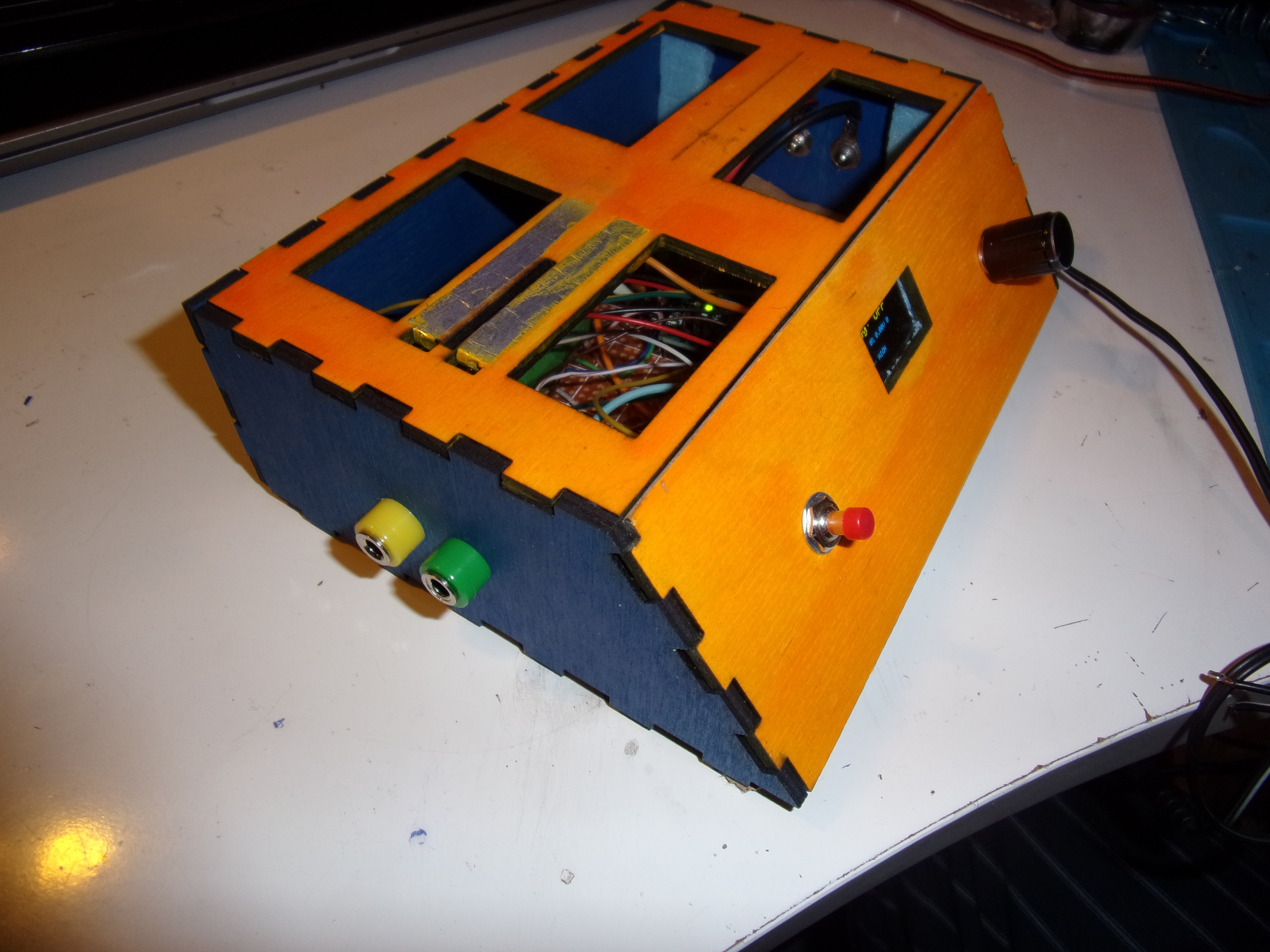
The positive of the 12V is connected to the metal track on the bench and is also connected directly to one of the outputs (yellow) to directly power the car on the track, if necessary.
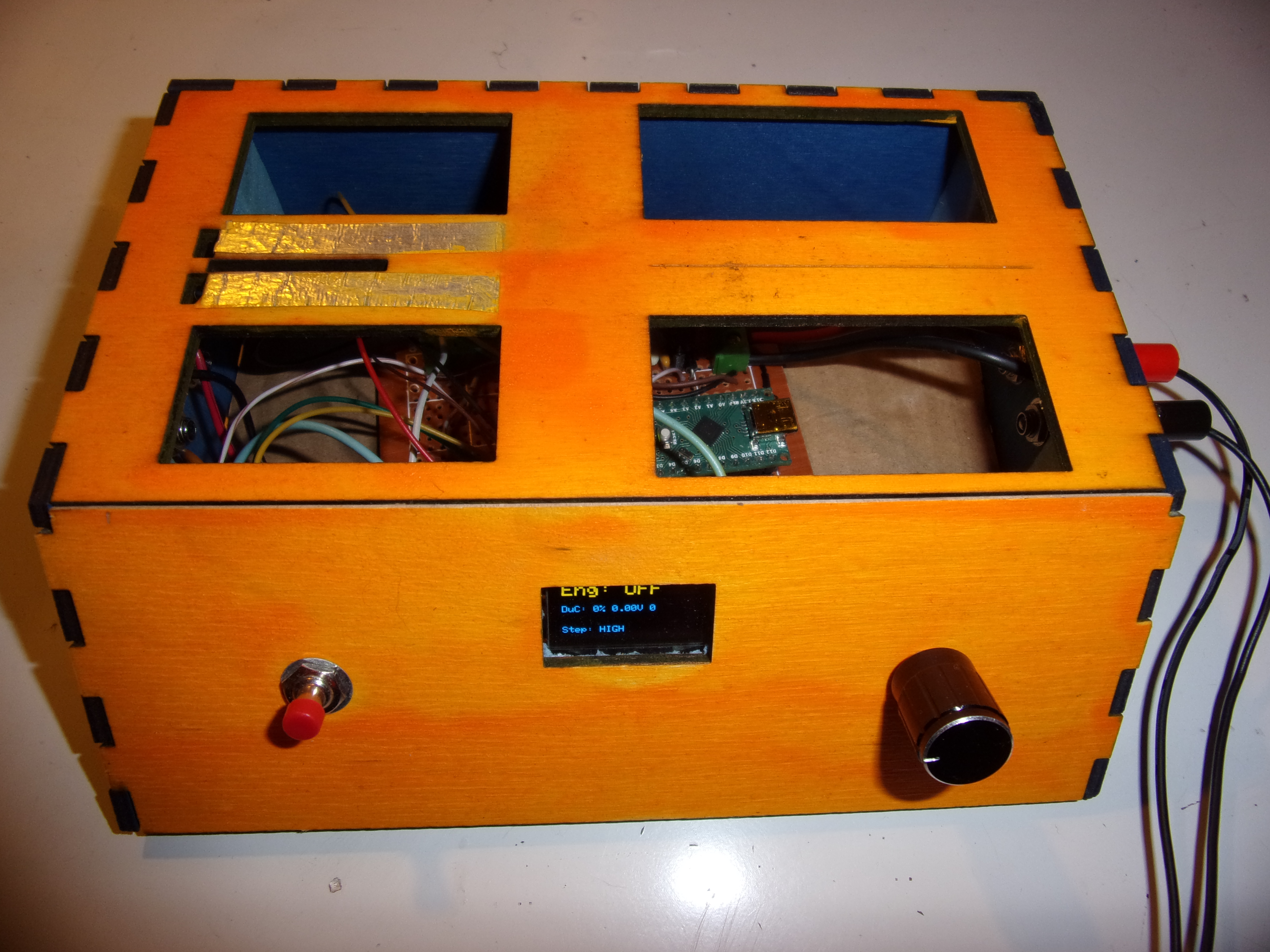
On the engine output there is the TIP120 (PWM) which is governed by Arduino. By rotating the encoder you adjust the supply voltage of the engine. The encoder is equipped with a button that is used to change the rotation step (High and Low). On High a small rotation generates a greater variation, on low you have a fine adjustment. The button activates and deactivates the PWM (engine ON and OFF).
As I was saying, it is possible to use the bench as a controller for a ghost car.
N. B.: it is necessary to power the tracks directly. You need to know how the slot car track works. Pay attention to the polarity. If you don't know how the track works, in the best case it won't work, otherwise you risk doing DAMAGE!!!!
It is possible to use two ways to control a car on the track.
The first is to use the bench's power supply to also supply current to the track. The power supply must be sufficiently powerful, at least 2A.
The yellow connector receives 12V, and must be connected to the + (positive) track, which we will call input. Between the two tracks there is obviously the motor. The second track, which we will call output, must be connected to the green connector. Nothing else is needed. If everything is connected correctly, the car can be controlled via the encoder.
The second way requires that the track be powered separately, in its standard mode. The bench must be inserted in place of the manual controller.
The bench must always be powered with 12 volts, to power Arduino.
Since the input rail (positive) is already powered by the track, we only need to connect the output rail to the green connector.
To close the circuit, it is necessary to connect the GND of the two power supplies (pay close attention to this operation).
Since I use banana connectors, I make a bridge between the black connector of the bench power supply and the negative connector of the track power supply.
EXPANDED TECHNICAL DETAILS
High-Performance Racing Diagnostics
This professional bench tool provides slot-car racers with a "Dyno" for testing motor performance and a high-precision digital controller.
- RPM & Volt-Ampere Logging: The Arduino captures the motor's RPM using a hall-effect sensor and simultaneously monitors current draw. This data is displayed on a high-refresh-rate LCD for engine tuning.
- Contactless Optical Braking: (Advanced version) Replaces standard resistive brakes with a PWM-driven "Electronic Brake" handled by the Arduino, allowing for infinitely adjustable braking curves for every car.
Software
- Arduino IDE 2.0 (Beta) Optimized: Leverages the high-speed autocomplete and debugging features of the new IDE to refine the "Dynamic Braking" and "Throttle Curve" algorithms.