
Hello!
This project presents the improvements made to my original (and first) project, the Automated Solar Powered Horizontal Blinds. The original design posted met the requirements at the time. It operated correctly for nearly 4 months before some design flaws became apparent.
To recap, the purpose of the blinds is to open and close based on light levels, to either let in light or close for privacy. And also the blinds should close when it gets "too hot," which is a completely arbitrary designation.
I imported this project from somewhere else, and the hardware/tools section here was just not giving me the options I wanted, so you'll have to deal with the itemized list as it is, instead of in the neat Hackster.io format. Sorry.
The new design does the following:
- Open (rotate to 85 degrees) in the morning to let in light
- Close (rotate to 0 degrees - blinds pointed down) in the evening to provide privacy
- Close (rotate to 165 degrees - blinds pointed up, against the sun) if the temperature exceeds a temperature of 30 C (~86 F) - this temperature is arbitrary, your comfort level may vary.
- Perform all of these activities with no external wiring, boxes, devices, etc. In other words, pass the Wife Acceptance Factor.
- Be sustainable enough that I don't abandon the project because I have to replace batteries too frequently.
- Don't cost too much. I think the end result is that the blinds can be built for about $50 US. Money invested in new tools, and time spent programming, testing, soldering, and tinkering, of course, don't count.
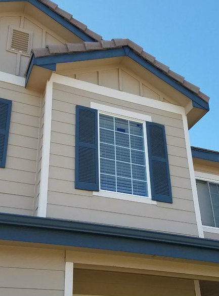
The reason for these design requirements are that the window for which they were designed is a 2nd floor window over the front door of the house. This window faces South (really, SSE), which means there is a lot of sunlight (and potential warmth) in the winter with the blinds open, but the potential for too much heat in the summer.
As stated, the blinds worked perfectly for about 4 months (January install, they came back down in about June). The flaws discovered were:
- The house does not face due South..... Therefore in winter, the sun is on the window most of the day, only leaving the window late in the afternoon. This provides lots of solar charging during the winter. During the summer, however, the sun goes over the house by noon, which means there is not enough sun to charge for a large portion of the daylight hours. And the solar panel's original placement in the window gets shaded for the first few hours of the day, on top of that. Solution: Better solar panel position.
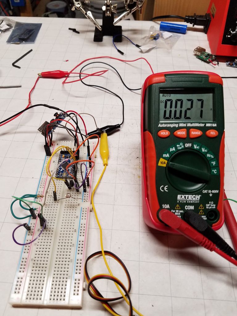
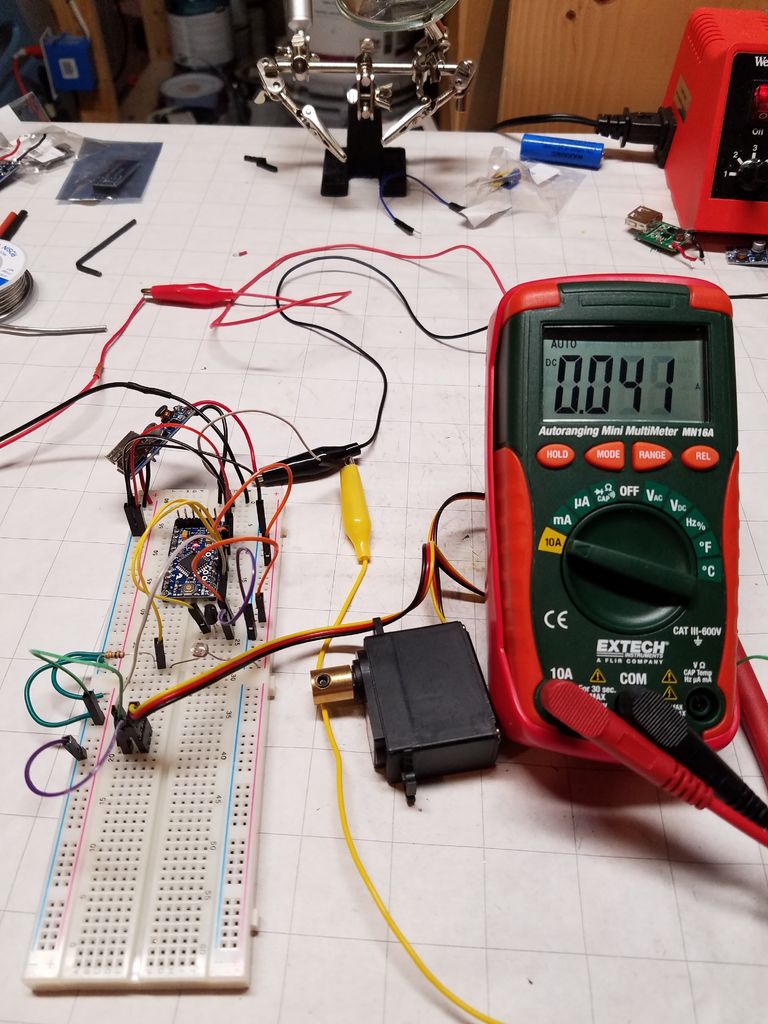
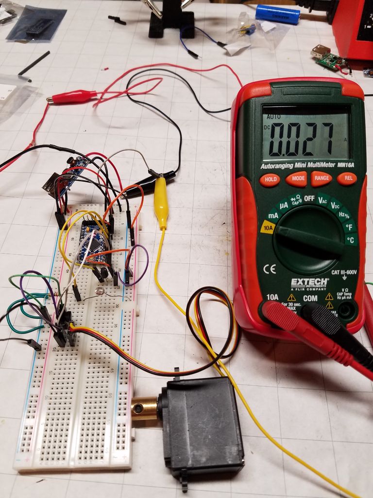
- The servo motor used to control the blinds draws a continuous 13 mA. This shocked me. In my first attempt, I did not measure current with the servo in place because my multimeter couldn't support the large draw of the servo and provide the accuracy to see that when in "sleep." Solution: High-Side Switch using a PNP Transistor.
- My original design 6V solar panel actually works against the LiPo charging module. The charging module has a rated input of 4.5V to 5.5V. When the panel received full sun and generated 6V or more of electricity, the charging module shut down. I didn't discover this until after the blinds had been installed. Solution: correctly sized panel.
- No logging/telemetry collection. This made it really difficult to diagnose the blinds when they started to malfunction. Solution: EEPROM Logging function.
- There was no way to connect/disconnect to diagnose/fix. This applied to both the solar panel and the battery. Solution: JST Connectors between battery and circuit, solar panel and circuit.
- Measurements (temperature and light) need to be against a solid 5V reference voltage (VCC out on the Arduino), NOT the 5V output of the DC-DC booster. That voltage can vary a bit, which impacts the measurements of the Analog-to-Digital conversion. In my first design, the "5V" line I used was actually the unregulated line coming off the DC-DC booster. Solution: Seems obvious, doesn't it? Use the *regulated* 5V output from the Arduino Pro Mini.
So let's get started!
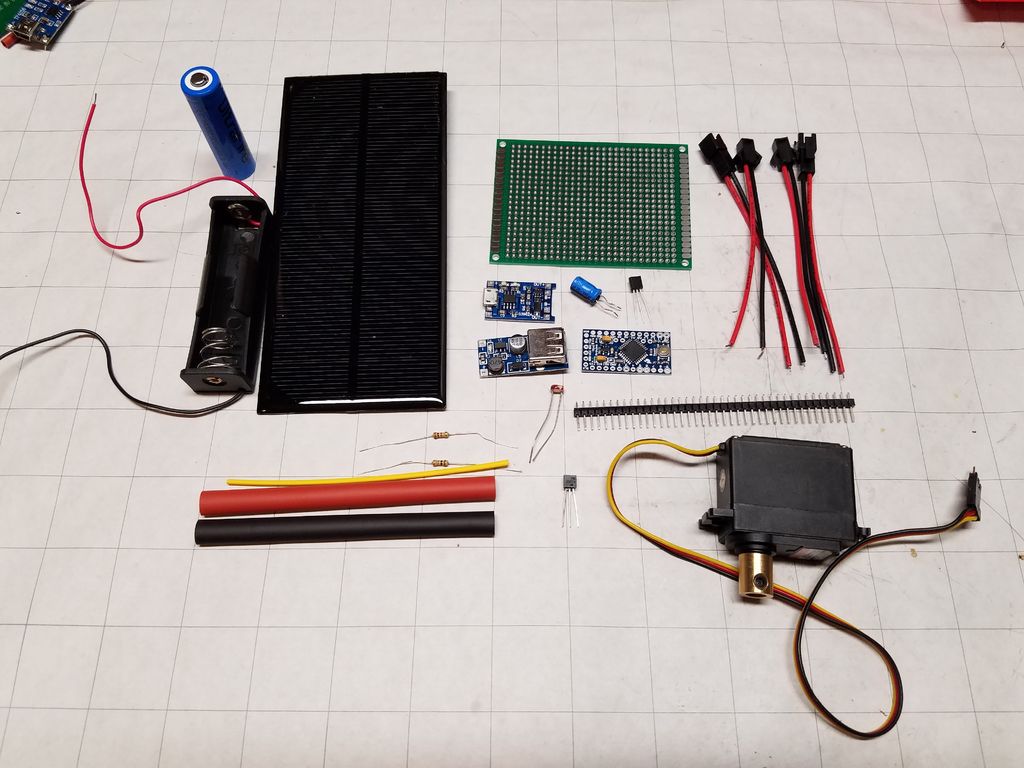
Step 1: Parts List
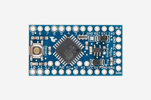
I chose to use an Arduino for this project. It's what I know. You could use another micro controller, whatever suits you. You'll notice I buy a lot from SparkFun - they're local to me. What's great about it is that I can place an order in the morning and then go pick it up that afternoon.
Other links you'll see are from banggood.com - they have a lot of cheap components, and a wide variety of electronics parts. If you're comfortable waiting for up to a month or more for your parts, you can get stuff cheap. And from taydaelectronics.com. If you can buy several things at once, the prices are VERY good. Shipping is quite reasonable. So some of the parts you'll see in my list I actually ordered 5, 10, or 20 items in order to get to an order minimum. Who knows, maybe I'll build several of these.
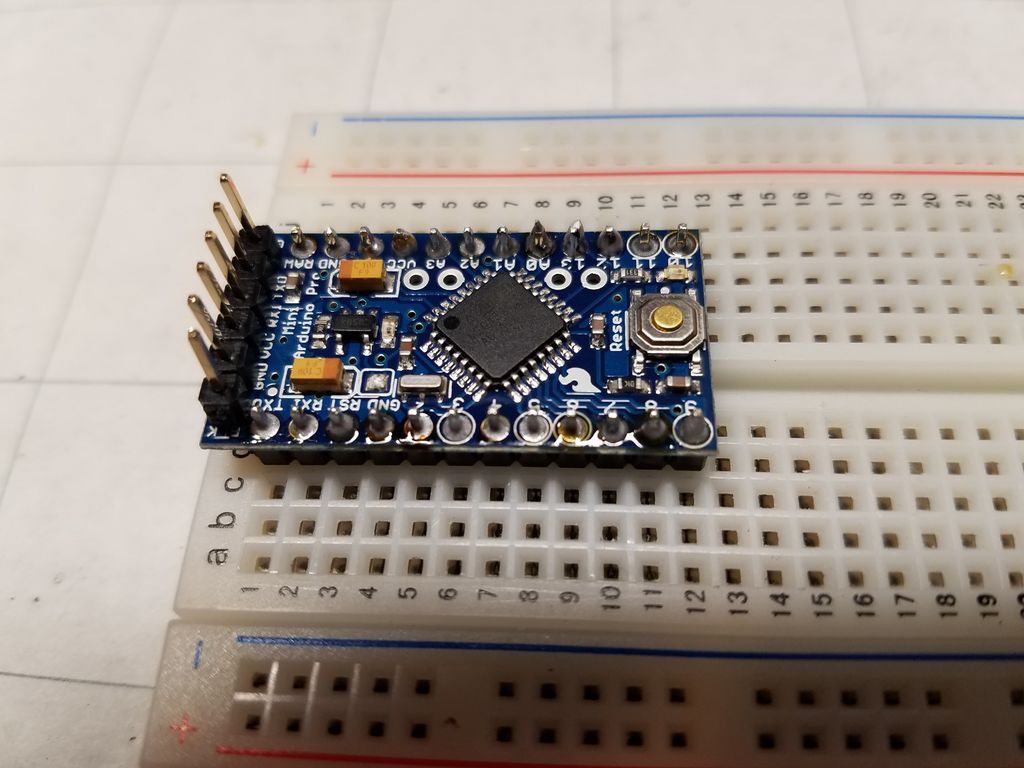
- Arduino Pro Mini ($10 - SparkFun)
- Arduino Uno, for programming the Mini - you can use special cables, but this setup works for me.
- LM35DZ temperature sensor ($1.23 - Tayda)
- PN2907A PNP transistor ($0.05 - Tayda)
- Light Dependent Resistor (LDR) ($1.24 for a 10pc pack from banggood.com) -
- One (1) 10K-Ohm Resistor ($0.01 - Tayda) - though I bought a resistor pack from SparkFun for $8.
- One (1) 1K-Ohm Resistor
- 5V 1.5W Solar Panel ($4.07 - banggood.com)
- 5V DC-DC Booster ($1.38 - banggood.com)
- Lithium Battery Charging module ($2.89 for a 3pc pack from banggood.com)
- JST Connectors ($3.33 for a 60-pack from banggood.com)
- Rechargeable 3.6V Lithium battery ($15.39 for a 4-pack from Amazon, includes a wall wart charger)
- 18650 battery holder ($1 - SparkFun)
- Servo motor (I used a Hitec HS-325HB that I found at a local hobby store) (Here's an equivalent) I had to take a guess at what kind of torque was necessary. I couldn't find a reasonably-priced torque wrench to make a measurement.
- Servo motor coupling. Because I used a Hitec Servo, I needed this. ($5 - SparkFun)
- 100 uF capacitor ($0.03 - Tayda)
- Assorted hook-up wire (I bought this kit - $17.79 on Amazon)
- PCB ($2.74 for a 10 pack from Amazon)
Step 2: Tools
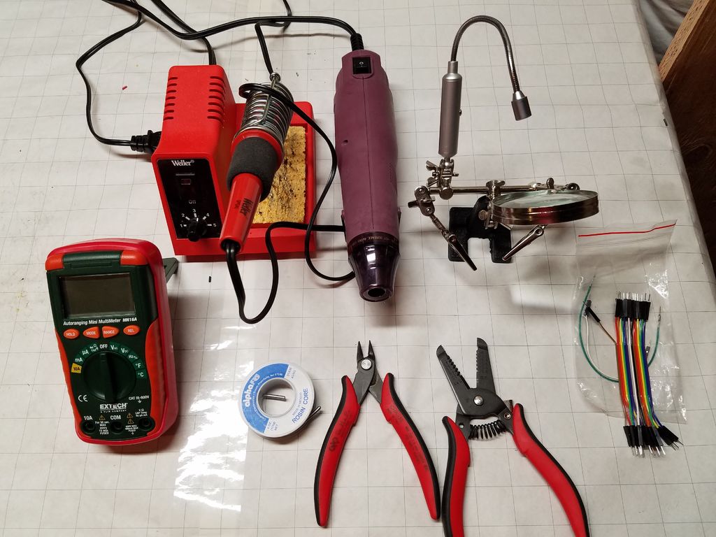
Useful items to have:
- Drill
- Soldering Iron
- SolderWire
- Wire clippers
- Wire stripper
- Multimeter
- Dremel or similar small cutting tool
- Circuit board/Solder breadboard
- Heat-shrink wrap
Step 3: Prototype the project
OK. So now that you've got all your components and a work area, it's time to throw it all together and see what happens.
In the original project, the first thing I did was hook up two AA batteries to the 5V DC-DC booster and verify I got 5V of output. This time around, I did the same, only with the actual battery, the Lithium rechargeable 3.6V battery. Fully charged, it sits at 4.1-4.2V. According to my multimeter, I get 5.04V out of the booster. Good enough.
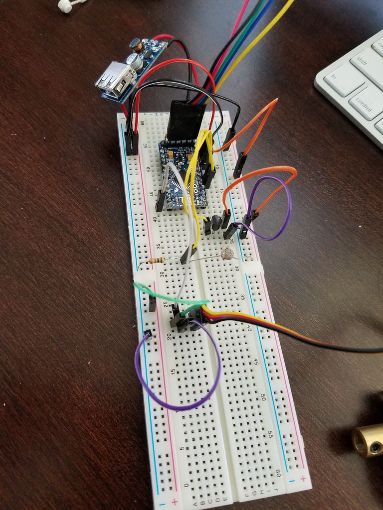
The next step I took was to lay out all the components on a solderless breadboard, in order to write the code to control it, as well as take current and voltage measurements.
- Connect the appropriate connectors of the Lithium charging module to the battery and the solar panel (Positive to positive, negative to negative)
- Connect a wire from the panel positive terminal to analog A0 - this provides panel voltage for logging.
- The battery connects to the 5V DC-DC booster as well.
- Connect a wire from the battery positive terminal to analog A1 - this provides the battery voltage for logging.
- The 5V output from the booster goes to the RAW input on the Arduino.
- Ground from the 5V booster is used throughout.
- Connect the Arduino VCC pin to everything that needs regulated 5V.
- The servo can connect to the 5V output of the DC-DC booster, but it will go through the PNP transistor first.
- From the LDR, connect the 10K-Ohm resistor to ground. Connect a wire between the LDR and the resistor to Analog A3 - this is your light detection.
- Connect 5V to the 5V side of the LM35DZ (or your temperature sensor)
- Connect Ground of the LM35DZ to Ground.
- Connect a wire from the middle (or Output) pin of the LM35DZ to A2 - this is your temperature sensing.
- Connect 5V output from the DC-DC booster to the E (Emitter) pin of the PN2907A.
- Connect a 1K-Ohm resistor between the B (Base) pin of the transistor to pin 11 - this is the control to allow current to flow to the servo motor.
- Connect the C (Collector) pin of the transistor to the power pin