To have a round display and not be able to draw neat gauges is a pity. I created a sketch to just do that, three times on different sides of the display. The sketch draws a circular gauge with three zones of different color. As a “bonus” there is also a sample pointer hand that one can adapt to disparate application uses. If you just need it –now!- go to the attached sketch and use it, if you want to understand how to do it and perhaps improve (or correct) what I did, read the following lines about the “theoretical approach” I used. My article is a proposal of a method so I do not add any instructions on how to connect your specific round display to whatever Arduino you may have, there are plenty of resources for that. I have listed the two components that I have now on my desk (a 1.28" display and an Arduino MKR1010).
Whatever the library there are primitives to draw circles and triangles but not a circular crown (annulus); so what we need to do is draw some triangles and then, on top, draw a circle of the same color of the background.
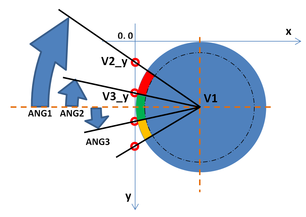
The second triangle (GREEN) will have one vertex above the horizontal center line and the other below, therefore:
- 120 minus tan(ANGLE_2) and 120 plus tan(ANGLE_3)
The third t. (ORANGE) will be all below with y coordinates … 120 + tan(ANGLE_2) and 120 + tan(ANGLE_1). At the end we go back to ANGLE_1 to respect the symmetry of the dial. The outer limits, the partition of the segments and the colors need to be memorized somewhere, so we have an array with the following content:
- ANGLE_1, ANGLE_2, ANGLE_3, COLOR_1, COLOR_2, COLOR_3
As I wanted to draw a dial on left, bottom and right sides I made it a 3 by 6 matrix to have independent dimensions and color composition of each of the dials. To draw them with the least code possible I used the ROTATION function and repeated the same calculation at each new rotation of the coordinates system.
At the end you need to cancel the “central/vertex” part of the triangles drawing a circle with r = (120 – dial_width) and the same color as the background.
Using this “rotation” technique it must be clear that each drawing has an UP and DOWN when on the “left” side as shown in the above picture. When you set you final operational rotation value, the UP and DOWN must be reassessed (i.e. if you draw three dials and then stop on rotation = 2 the right side dial will have the UP side down – this is the reason why the red color in the example is “inverted”). The same consideration must be made for the pointer hand that will show the value on the dial.
Technical Implementation: Round Pixels and Gradients
This project reveals the hidden layers of simple dial-to-digital interaction:
- Optical Interface layer: A circular TFT, such as the GC9A01, acts as a high-resolution digital eye, providing a bright and clear 240x240 pixel grid in a unique circular form factor.
- Protocol layer: The Arduino (or ESP32) uses the SPI bus to transmit high-performance graphics commands and pixel data.
- Input Strategy layer: A Rotary Encoder provides high-precision incremental input for menu navigation or value adjustment.
- Conversion layer: The Arduino code follows a "sequential decoding" (or quadrant-step) strategy: it interprets the dial rotation and matches the graphics "Needle" or "Bar" to a value.
- Visual Interface layer: Custom UI elements like "Gradients" and "Shadows" coordinate the display tasks to provide a premium feel.
Hardware Infrastructure
- Arduino/ESP32: The "brain" of the project, managing high-speed SPI graphics rendering and coordinating the encoder tasks.
- GC9A01 Circular TFT: Providing high-power and elegant visual feedback for the smart-dial interface.
- Rotary Encoder: Providing tactile physical feedback for every point of the menu's navigation.
- TP4056 & Li-Po: Essential for providing power and energy-efficient charging for a portable dial.
- 3D-Printed Case: Acts as a high-performance mechanical housing for every point of the dial.
- Micro-USB Cable: Used to program the controller and provide the primary power source for the project.
Navigation and Interaction Step-by-Step
The smart dial process is designed to be very efficient:
- Initialize Hardware: Correctly seat the TFT and encoder in the 3D-printed base and connect to the controller SPI pins.
- Setup Graphics Sync: In the
setup()function, initialize the GC9A01 display, the Serial port, and the graphics buffer (e.g.,Arduino_GFX). - Execution Loop: The Arduino waits for encoder movement and updates the display graphics in real-time to match the dial.
- Visual Feedback Integration: Watch the custom UI automatically become a rhythmic visual signal, pulsing and following the dial settings on the screen.
Future Expansion
- OLED Identity Dashboard Integration: Add a second small OLED display inside the dial box to show "Battery Level" (%) or "WiFi SSID."
- Multi-sensor Climate Sync Synchronization: Connect a DHT22 sensor to display the current "Room Temperature" or "Humidity" as a stylized meter.
- Cloud Interface Registration Support Synchronization: Add a WiFi/BT module and link to a smartphone dashboard to control central heating or lights via the smart dial.
- Advanced Velocity Profile Customization Support: Add specialized "Haptic Feedback" (using a vibration motor) to provide a physical "Tick" when the dial hits a menu item.
Smart dials for round displays is a perfect project for any electronics enthusiast looking for a more interactive and engaging UI-to-hardware tool!
[!NOTE] Ensure your circular display is centered in the dial housing to avoid light leaks and parallax errors during navigation!